
A subscription to JoVE is required to view this content. Sign in or start your free trial.
Method Article
تلفيق من السيليكا عالية جدا Microresonators عامل الجودة
In This Article
Summary
وصفنا في استخدام تقنية ليزر ثاني أكسيد الكربون إنحسر الى افتعال تجاويف السيليكا الرنانة، بما في ذلك قائمة بذاتها المجهرية وmicrotoroids على الرقاقة. طريقة إنحسر يزيل العيوب السطحية، مما يسمح للأعمار الفوتون طويلة داخل كلا الجهازين. الأجهزة الناتجة لديها من العوامل ذات جودة عالية جدا، وتمكين التطبيقات التي تتراوح بين الاتصالات السلكية واللاسلكية إلى biodetection.
Abstract
Whispering gallery resonant cavities confine light in circular orbits at their periphery.1-2 The photon storage lifetime in the cavity, quantified by the quality factor (Q) of the cavity, can be in excess of 500ns for cavities with Q factors above 100 million. As a result of their low material losses, silica microcavities have demonstrated some of the longest photon lifetimes to date1-2. Since a portion of the circulating light extends outside the resonator, these devices can also be used to probe the surroundings. This interaction has enabled numerous experiments in biology, such as single molecule biodetection and antibody-antigen kinetics, as well as discoveries in other fields, such as development of ultra-low-threshold microlasers, characterization of thin films, and cavity quantum electrodynamics studies.3-7
The two primary silica resonant cavity geometries are the microsphere and the microtoroid. Both devices rely on a carbon dioxide laser reflow step to achieve their ultra-high-Q factors (Q>100 million).1-2,8-9 However, there are several notable differences between the two structures. Silica microspheres are free-standing, supported by a single optical fiber, whereas silica microtoroids can be fabricated on a silicon wafer in large arrays using a combination of lithography and etching steps. These differences influence which device is optimal for a given experiment.
Here, we present detailed fabrication protocols for both types of resonant cavities. While the fabrication of microsphere resonant cavities is fairly straightforward, the fabrication of microtoroid resonant cavities requires additional specialized equipment and facilities (cleanroom). Therefore, this additional requirement may also influence which device is selected for a given experiment.
Introduction
An optical resonator efficiently confines light at specific wavelengths, known as the resonant wavelengths of the device. 1-2 The common figure of merit for these optical resonators is the quality factor or Q. This term describes the photon lifetime (τo) within the resonator, which is directly related to the resonator's optical losses. Therefore, an optical resonator with a high Q factor has low optical losses, long photon lifetimes, and very low photon decay rates (1/τo). As a result of the long photon lifetimes, it is possible to build-up extremely large circulating optical field intensities in these devices. This very unique property has allowed these devices to be used as laser sources and integrated biosensors.10
A unique sub-class of resonators is the whispering gallery mode optical microcavity. In these devices, the light is confined in circular orbits at the periphery. Therefore, the field is not completely confined within the device, but evanesces into the environment. Whispering gallery mode optical cavities have demonstrated some of the highest quality factors of any optical resonant cavity to date.9,11 Therefore, these devices are used throughout science and engineering, including in fundamental physics studies and in telecommunications as well as in biodetection experiments. 3-7,12
Optical microcavities can be fabricated from a wide range of materials and in a wide variety of geometries. A few examples include silica and silicon microtoroids, silicon, silicon nitride, and silica microdisks, micropillars, and silica and polymer microrings.13-17 The range in quality factor (Q) varies as dramatically as the geometry. Although both geometry and high Q are important considerations in any field, in many applications, there is far greater leverage in boosting device performance through Q enhancement. Among the numerous options detailed previously, the silica microsphere and the silica microtoroid resonator have achieved some of the highest Q factors to date.1,9 Additionally, as a result of the extremely low optical loss of silica from the visible through the near-IR, both microspheres and microtoroids are able to maintain their Q factors over a wide range of testing wavelengths.18 Finally, because silica is inherently biocompatible, it is routinely used in biodetection experiments.
In addition to high material absorption, there are several other potential loss mechanisms, including surface roughness, radiation loss, and contamination loss.2 Through an optimization of the device size, it is possible to eliminate radiation losses, which arise from poor optical field confinement within the device. Similarly, by storing a device in an appropriately clean environment, contamination of the surface can be minimized. Therefore, in addition to material loss, surface scattering is the primary loss mechanism of concern.2,8
In silica devices, surface scattering is minimized by using a laser reflow technique, which melts the silica through surface tension induced reflow. While spherical optical resonators have been studied for many years, it is only with recent advances in fabrication technologies that researchers been able to fabricate high quality silica optical toroidal microresonators (Q>100 million) on a silicon substrate, thus paving the way for integration with microfluidics.1
The present series of protocols details how to fabricate both silica microsphere and microtoroid resonant cavities. While silica microsphere resonant cavities are well-established, microtoroid resonant cavities were only recently invented.1 As many of the fundamental methods used to fabricate the microsphere are also used in the more complex microtoroid fabrication procedure, by including both in a single protocol it will enable researchers to more easily trouble-shoot their experiments.
Protocol
1. Microsphere تلفيق
- حدد كمية صغيرة (حوالي 5 بوصة) من الألياف الضوئية، وقطاع ~ 1.5 "الكسوة واحدة من نهاية وتنظيف إما مع الميثانول أو الايثانول (الشكل 1A، ب).
- إذا كانت متوفرة، يلتصق نهاية مع الساطور الألياف البصرية. إذا لم يتوفر، وقطع مع قواطع للاسلاك أو مقص بحيث يتم ترك ~ 0.5 ". وميزة استخدام الألياف البصرية الساطور هو أنها تنتج على نحو سلس جدا، وقطع موحدة كما في الشكل 1B. خشونة الزائدة أو عيوب من قطع قد يسبب إنحسر متفاوت، وتخفيض عامل الجودة من المجالات الناتجة عن ذلك.
- كشف نهاية الألياف تنظيفها إلى 3W من قوة ليزر ثاني أكسيد الكربون 2 ركز على ~ 500μm قطرها حجم البقعة لل~ 1 ثانية (الشكل 1C، د، ه). وتنتج هذه المجالات ~ 200μm في القطر، ولكن يمكن ضبطها حجم بالزيادة أو النقصان القطر من الألياف البصرية. تعديل طفيف قد كثافة الليزر أيضا باللازمة لمجالات إنحسر أكبر أو أصغر ه.
2. Microtoroid تلفيق
- تصميم وصنع الضوئية الرئيسية مع الدوائر، والظلام الصلبة، في التباعد وقطر من اختيارك. من المهم أن نلاحظ أن toroids المنتجة ستكون 25-30٪ أصغر من الدوائر على القناع. على سبيل المثال، فإن دائرة الصلبة التي يبلغ قطرها 100 ميكرون إنتاج حلقي التي يبلغ قطرها حوالي 75 ميكرون. أيضا، فمن المستحسن أن يترك ما لا يقل عن 1-2mm في المسافة بين كل دائرة وعلى الأقل 5mm من الفضاء بين صفوف من دوائر وحول حواف قناع. منذ يجب أن يكون التعامل معها بعناية رقائق عينة مع ملاقط، من المهم أن يترك مساحة للملاقط إلى قبضة دون الإضرار toroids. مساحة إضافية كما يوفر مجالا للألياف الضوئية مدبب على ضوء زوجان في الأجهزة المصنعة، ويسمح بخفض عينات إلى أصغر المصفوفات أكثر سهولة. لهذا الإجراء، استخدمنا قناع مع صفوف من دي ميكرون 160الدوائر ameter ~ 1MM بعيدا، مع 5mm ~ المسافة بين كل صف من الدوائر. وtoroids أنهى ما يقرب من 110 ميكرون في القطر.
- تبدأ مع رقائق السيليكون مع طبقة سميكة من 2 ميكرومتر السيليكا نمت حراريا. يلتصق رقائق لتناسب نمط microdisk المطلوب على قناع ضوئيه، مما يترك مجالا للمقاومة للضوء حافة حبة. لاحظ أنه في بداية من تلفيق، فإنه عادة ما يكون الأكثر ملاءمة لصفائف عدة حفر من الدوائر على أكبر قطعة من رقائق السيليكون (~ الطول عدة سم X عدة). أكبر رقائق تسمح ضوئيه والبنك البريطاني الحفر من أكثر العينات في وقت واحد، ويتم التعامل معها بسهولة أكبر مع ملاقط. في وقت لاحق، وذلك قبل الحفر XeF الخطوة 2، فمن المستحسن أن يلتصق أكبر إلى أصغر رقائق صفائف للسماح أسرع وأكثر اتساقا XeF 2 الحفر.
- في fumehood، تماما تنظيف رقائق من قبل الشطف مع الميثانول، الأسيتون، الأيزوبروبانول، والماء منزوع الأيونات. ضربة العينات الجافة باستخدام النتروجين أو شركات تمت تصفيتهاضبط ressed بندقية الهواء، ووضعها على طبق من ذهب حار إلى 120 درجة مئوية لمدة لا تقل عن 2 دقيقة حتى يجف.
- بعد السماح للرقائق بارد، ووضعها في fumehood القابلة للاشتعال / المذيبات وفضح لHMDS لمدة 2 دقيقة باستخدام طريقة ترسيب البخار. وترسب بخار بسيط الأسلوب: وضع بضع قطرات من HMDS في كوب صغير 10ML، ومن ثم تغطية وعاء رقائق صغيرة مع وعاء زجاجي أكبر لعقد بخار.
- وضع عينة على الدوار مع جبل بحجم مناسب. باستخدام زجاجة قطارة أو حقنة والتصفية، وتطبيق الواقي الضوئي للعينة. تدور معطف S1813 مقاومة للضوء على كل عينة لمدة 5 ثوان في 500rpm، تليها 45 ثانية في 3000rpm. ليست هناك حاجة حافة حبة إزالة إذا كانت الرقاقة كبيرة بما فيه الكفاية بحيث حبة حافة لا تتداخل مع الزخرفة.
- لينة خبز مقاوم الضوء على طبق ساخن على 95 درجة مئوية لمدة 2 دقيقة.
- باستخدام قناع اليجنر الأشعة فوق البنفسجية والضوئية الرئيسية المطلوبة، يعرض عينات مقاومة للضوء المغطاة إلىمجموعه 80mJ/cm 2 من الأشعة فوق البنفسجية.
- تزج العينات في المطور MF-321 لإزالة مقاومة للضوء والتي تعرضت للأشعة فوق البنفسجية. في حين النامية، وتراقب عن كثب كما يتم إزالة مقاوم الضوء من رقاقة وحلها. من المهم أن يحرك / حفيف الحاوية باستمرار خلال هذه العملية لضمان إزالة مقاومة للضوء بشكل موحد. للمعلمات معينة، ومقاومة للضوء يأخذ حوالي 30 ثانية للتطوير.
- عندما أكثر من مقاومة للضوء غير مرغوب فيه قد حلت في المطور، شطف العينات بدقة تحت الماء الجاري، ضربة بلطف تجفيف العينات باستخدام النتروجين أو بندقية الهواء، وفحص العينات تحت المجهر للتأكد من تمت إزالة كل مقاومة للضوء غير مرغوب فيها. إذا لزم الأمر، يمكن أن تكون مغمورة العينات مرة أخرى في التطوير، ولكن ينبغي للمرء أن يكون حريصا على عدم تنمية متزايدة العينات كما يمكن أيضا أنماط مقاومة للضوء المطلوب للتلف. (إذا كان المطلوب من أنماط التالفة أو المعيبة، يمكن أن تكون مقاومة للضوءإزالة مع الأسيتون والخطوات التي يمكن أن تتكرر مرة أخرى 2،1-2،9).
- بعد النامية، وشطفها جيدا العينات في المياه الجارية، ضربة بلطف تجفيف العينات، وخبز الثابت لهم على طبق ساخن على 110 درجة مئوية لمدة 2 دقيقة. هذه الخطوة مع ارتفاع درجات الحرارة ومقاومة للضوء فوق الزجاج في درجة الحرارة التي تمر بمرحلة انتقالية، الإنحسار ومقاومة للضوء وخشونة إصلاح جزئيا التي وقعت خلال عملية النامية.
- باستخدام أواني التفلون والمعدات اللازمة واقية، غمر العينات في تحسين ضوئي أكسيد مخزنة (البنك المركزي البريطاني). BOE يحتوي HF، الذي يحفر في السيليكا التي لا تغطيها مقاومة للضوء لتشكيل منصات السيليكا التعميم على رقاقة السيليكون (الشكل 2A-C). تحسن HF مخزنة تنتج أكثر سلاسة حفر، التقليل من خشونة في الدوائر السيليكا الناتجة عن ذلك. في حين أنه من الممكن خلط مخزنة HF HF بدءا من 49٪، وهذا يمكن أن يؤدي إلى نتائج شديدة التباين وعادة ما تتم كميات صغيرة فقط.
- بعد حوالي 15-20 دقيقة (دepending على عينة الأنماط والأحجام وعدد العينات)، وإزالة عينات من البنك البريطاني باستخدام تفلون ملاقط. شطف بعناية العينات في المياه الجارية. تمت إزالة السيليكا عندما العينات أصبح مسعور.
- بعد الحفر، الشطف، وتجفيف العينات، وتفتيشها باستخدام المجهر الضوئي. تحقق للتأكد من تم محفورا أنماط المطلوب تماما وتمت إزالة جميع السيليكا غير المرغوب فيها. إذا لزم الأمر، والعودة العينات الى البنك البريطاني للمزيد من الحفر. وينبغي للمرء أن يكون حريصا على عدم overetch العينات، أو قد يكون معطوبا أنماط دائرية تحت مقاومة للضوء.
- مرة واحدة الحفر BOE كاملة، شطف جيدا العينات في الماء منزوع الأيونات وضربة الجافة. إذا كانت العينات على قطع كبيرة من رقاقة السيليكون، ويوصى أيضا على قطع منها (باستخدام منشار أو التكعيب الكاتب الماس) إلى أجزاء أصغر مع الصفوف الفردية من الدوائر السيليكا. وحفرت الصفوف الفردية من الدوائر بسرعة أكبر وبشكل موحد في XeF2 خطوة الحفر (2.16). تتم إزالة الغبار السيليكون التي تنتجها عدة قطاعات خلال تنظيف في الخطوة التالية.
- إزالة مقاومة للضوء وذلك بدهن مع الميثانول، الأسيتون، الأيزوبروبانول، والماء منزوع الأيونات، وتجفيف العينات باستخدام بندقية النيتروجين والتدفئة على طبق من 120 ° C ساخنة لما لا يقل عن 2 دقيقة.
- باستخدام مطبوع 2 XeF، تنتقص من السيليكون تحت منصات السيليكا دائري لتشكيل microdisks السيليكا (الشكل 2D-F). يجب أن يكون محفورا مبلغ يقارب 1/3 من حجم الدائرة السيليكا، وبذلك يتسنى للعمود microdisk الناتج هو 1/3-1/2 ما يقرب من قطر القرص الإجمالي، على النحو الذي يحدده التفتيش مع المجهر الضوئي. عدد النبضات 2 XeF ومدة كل نبضة يعتمد على كمية من السيليكون في الغرفة ونوع مطبوع 2 XeF المستخدمة.
- بعد الحفر 2 XeF، يعرض عينات لشعاع ليزر ثاني أكسيد الكربون وركزت 2 في ما يقرب من 1يتم تشكيل 2W كثافة ثوان 3 ~ أو حتى حلقي السلس (الشكل 2G-I). قد تكون هناك حاجة اعتمادا على حجم الدقيق للقرص ومقدار XeF 2 تقوض، وكثافة أعلى قليلا أو أقل، ومدة التعرض لتشكيل microtoroid. من المهم أن يتم محاذاة وسط شعاع الليزر ومركز microdisk، بحيث microdisk السيليكا ستشكل على نحو سلس، microtoroid دائري.
3. ممثل النتائج
ولا يمكن تصوير الأجهزة microsphere وmicrotoroid باستخدام كل من المجهر الضوئي والمجهر الإلكتروني (الشكل 1D، والبريد، والشكل 2H، ط). في جميع الصور، والتوحيد من سطح الجهاز هو واضح بشكل واضح.
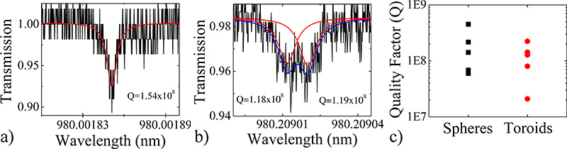
للتحقق من أن نهج مفصل يخلق فائقة س الأجهزة، ونحن تتميز أيضا عامل س من العديد من الأجهزة عن طريق إجراء (Δλ) linewidth قياس واحتساب المحملةس من تعبير بسيط: س = λ / Δλ = ωτ، حيث λ = الطول الموجي الرنانة، ω = تردد، وτ حياة الفوتون =. ويرد أطياف ممثل عن كل جهاز ملفقة باستخدام الإجراءات التفصيلية سابقا 1،9 و رسم بياني مقارنة بين العديد من الأجهزة في الشكل 3. عوامل الجودة لجميع الأجهزة هي أكثر من 10 مليون نسمة، وغالبيتهم من أكثر من 100 مليون نسمة.
وكان هذا الطيف من microsphere صدى واحد، مشيرا إلى أن ضوء يقترن إما إلى وضع عقارب الساعة أو عكس اتجاه عقارب الساعة بصري التكاثر. ومع ذلك، عرضت لطيف من حلقي صدى الانقسام، مشيرا إلى أن ضوء بالإضافة إلى وسائط على حد سواء في اتجاه عقارب الساعة وعكس اتجاه عقارب الساعة في وقت واحد. هذه الظاهرة تحدث عندما يكون هناك نقص طفيف في موقع اقتران. من المناسب للطيف لLorentzian المزدوج، يمكن تحديد عامل س كل من وسائط. والظاهرة الانقسام صدىيمكن أن تحدث في كل من نا المجال ومرنانات حلقي، ولكن على نحو أكثر تواترا لوحظ في toroids كما هم أكثر عرضة للعيوب ولها وسائل أقل البصرية مقارنة المجالات.

الرسم البياني رقم 1 التدفق. عملية تجويف تلفيق microsphere. أ) التقديم وب) مجهرية ضوئية من الألياف الضوئية وتنظيف المشقوق. ج) تقديم، د) صورة مجهرية ضوئية وه) مسح صورة مجهرية الإلكترون من microspere مرنان.

الرسم البياني رقم 2 التدفق. عملية تجويف تلفيق microtoroid. 1 التقديم)، ب) من أعلى إلى مشاهدة صورة مجهرية ضوئية وج) جنبا إلى رأي مسح صورة مجهرية الإلكترون من لوحة أكسيد دائري، على النحو المحدد من قبل ضوئيه والحفر على البنك البريطاني. لاحظ طفيف إسفين شكل أكسيد التي يتم تشكيلها من قبل البنك البريطاني. د) والتقديم، ه) من أعلى إلى رأي صورة مجهرية ضوئية وو) جنبا إلى رأي مسح صورة مجهرية الإلكترون من لوحة أكسيد بعد الحفر XeF الخطوة 2. لاحظ أن القرص أكسيد يحافظ على المحيط على شكل وتد. ز) التقديم، ح) من أعلى إلى مشاهدة صورة مجهرية ضوئية وط) جنبا إلى رأي مسح صورة مجهرية الإلكترون من تجويف microtoroid.

الشكل 3. أطياف الممثل عامل نوعية microsphere) أ و ب) تجاويف الرنانة microtoroid كما هو محدد باستخدام طريقة قياس linewidth. س في الأجهزة عالية جدا، ويمكن للمرء أن مراقبة الوضع تقسيم أو ذروة مزدوجة، والتي تعكس ضوء قبالة عيب صغير وتعمم في كلا الاتجاهين في اتجاه عقارب الساعة وعكس عقارب الساعة. ج) رسم بياني يوضح مقارنة العوامل س من microsphere عدة والتجاويف الرنانة microtoroid. اضغط هنا للحصول على أكبر شخصية .
= "jove_content"> 
الشكل 4. تخطيطي ليزر CO 2 إنحسر انشاء. وينعكس شعاع ليزر ثاني أكسيد الكربون 2 (الخط الأزرق الصلبة)، وركزت بعد ذلك على عينة. يمر من خلال 10.6 ميكرون / 633 نانومتر شعاع الموحد، الذي ينقل 10،6 ميكرون، ويعكس 633 نانومتر. الصور الضوئية العمود انعكاس للنموذج الخروج من شعاع الموحد، وبالتالي، كانت الصورة الحمراء إلى حد ما. قائمة الأجزاء اللازمة لهذا الإعداد هو في الجدول رقم 4.

الشكل 5. reflowed بشكل غير صحيح microsphere) و ب) تجاويف الرنانة microtoroid. بسبب وضع غير صحيح ضمن شعاع، والجهاز هو سوء تشكيلها. ج) ونتيجة لضعف أو الطباعة الحجرية الضوئية الرئيسية الفقراء، وحلقي والقمر على شكل.
Discussion
كما هو الحال مع أي بنية البصرية، والحفاظ على النظافة في كل خطوة من عملية التصنيع ذات أهمية حاسمة. كما أن هناك العديد من الكتب المدرسية مكتوبة حول هذا الموضوع من الطباعة الحجرية وتلفيق، وليس المقصود الاقتراحات دون أن يكون شاملا، ولكن تسليط الضوء على عدد قليل من القضاي...
Disclosures
الإعلان عن أي تضارب في المصالح.
Acknowledgements
كان مدعوما من قبل صانع ألف مؤسسة أننبرغ زمالة بحوث الدراسات العليا، وكان يؤيد هذا العمل من قبل المؤسسة الوطنية للعلوم [085281 و 1028440].
Materials
| Name | Company | Catalog Number | Comments |
| اسم الجزء | شركة | فهرس العدد | تعليقات |
| الألياف الكاتب | نيوبورت | F-RFS | اختياري |
| الألياف البصرية | نيوبورت | F-SMF-28 | ويمكن استخدام أي نوع من الألياف البصرية. |
| الألياف الطلاء متجرد | نيوبورت | F-STR-175 | ويمكن أيضا أن تستخدم تقشير الأسلاك |
| الإيثانول | أي بائع | مذيب مستوى نقاء | الميثانول أو الأيسوبروبانول هي بدائل |
الجدول رقم 1. مواد تصنيع Microsphere.
| اسم كاشف | شركة | <عدد قوي> كتالوج | تعليقات |
| رقائق السيليكون مع 2μm السيليكا نمت حراريا | WRS المواد | N / A | نحن نستخدم جوهري 8، <100> (4)، "بقطر |
| HMDS (Hexamethyldisilazane) | الدريتش | 440191 | |
| مقاومة للضوء | شيبلي | S1813 | |
| المطور | شيبلي | MF-321 | |
| مخزنة HF - تحسين | Transene | N / A | وHF تحسين مخزنة يعطي سلاسة، ونوعية أفضل من حفر BOE عادي أو HF |
| الأسيتون، والميثانول، الأيزوبروبانول | أي بائع | 99.8٪ نقاء |
الجدول 2. MICRمواد التصنيع otoroid.
| معدات اسم | الصانع | فهرس العدد | تعليقات |
| الغزال | Solitec | 5110-ND | ويمكن استخدام أي الدوار. |
| اليجنر | Suss Microtec | MJB 3 | ويمكن استخدام أي اليجنر. |
| XeF 2 مطبوع | أجهزة اتصال متطورة، وشركة | # ADCETCH2007 |
الجدول 3. Microtoroid معدات التصنيع.
| اسم الجزء | شركة | فهرس العدد | تعليقات |
| CO 2 ليزر | Synrad | مسلسل 48 | |
| 3 المحور مرحلة | OptoSigma | 120-0770 | متوفر من الشركات الأخرى أيضا. |
| سي العاكس 1 "قطر) | II-VI | 308325 | متوفر من الشركات الأخرى أيضا. |
| gimbal جبل الحركية (للسيليكون عاكس) | ثور مختبرات | KX1G | متوفر من الشركات الأخرى أيضا. |
| شعاع الموحد (1 "قطر) | ميلر البصريات | L19100008-B0 | متوفر من الشركات الأخرى أيضا. |
| 4 "طول العدسة (1" قطر) | ميلر البصريات أو الثاني سادسا: | متوفر من الشركات الأخرى وكذلك | |
| مشاركات متنوعة، يتصاعد عدسة | ثور مختبرات، نيوبورت، البصريات إدموند أو Optosigma | ||
| التكبير رؤية آلة 6000 نظام | Navitar | N / A | يتطلب عام USB الكاميرا وجهاز الكمبيوتر في الوقت الحقيقي التصوير. ويتم شراء هذا باعتباره عدة. |
| المصور لنظام 6000 تكبير | إدموند البصريات | 54-792 | متوفر من الشركات الأخرى أيضا. |
| محكمات وضع محور XZ ل6000 تكبير | باركر Daedal | CR4457، CR4452، 4499 | CR4457 هو المحور السيني، CR4452 هو محور Z-، 4499 وتزايد شريحة. |
الجدول 4. CO إنحسر ليزر 2 مجموعة المتابعة.
References
- Armani, D. K., Kippenberg, T. J., Spillane, S. M., Vahala, K. J. Ultra-high-Q toroid microcavity on a chip. Nature. 421, 925-928 (2003).
- Gorodetsky, M. L., Savchenkov, A. A., Ilchenko, V. S. Ultimate Q of optical microsphere resonators. Optics Letters. 21, 453-455 (1996).
- Armani, A. M., Kulkarni, R. P., Fraser, S. E., Flagan, R. C., Vahala, K. J. Label-Free, Single-Molecule Detection with Optical Microcavities. Science. 317, 783 (2007).
- Choi, H. S., Ismail, S., Armani, A. M. Studying polymer thin films with hybrid optical microcavities. Optics Letters. 36, 2152-2154 (2011).
- Aoki, T. Observation of strong coupling between one atom and a monolithic microresonator. Nature. 443, 671-674 (2006).
- Hsu, H. -. S., Cai, C., Armani, A. M. Ultra-low threshold Er:Yb sol-gel microlaser on silicon. Optics Express. 17, 23265 (2009).
- Zhu, J. On-chip single nanoparticle detection and sizing by mode splitting in an ultrahigh-Q microresonator. Nature Photonics. 4, 46-49 (2009).
- Zhang, X., Choi, H. -. S., Armani, A. M. Ultimate quality factor of silica microtoroid resonant cavities. Applied Physics Letters. 96, 153304 (2010).
- Vernooy, D. W., Ilchenko, V. S., Mabuchi, H., Streed, E. W., Kimble, H. J. High-Q measurements of fused-silica microspheres in the near infrared. Optics Letters. 23, 247-249 (1998).
- Saleh, B. E. A., Teich, M. C. . Fundamentals of Photonics. , (2007).
- Ilchenko, V. S. Crystal quartz optical whispering-gallery resonators. Optics Letters. 33, 1569-1571 (2008).
- Soteropulos, C., Hunt, H., Armani, A. M. Determination of binding kinetics using whispering gallery mode microcavities. Applied Physics Letters. 99, 103703 (2011).
- Barclay, P. E., Srinivasan, K., Painter, O., Lev, B., Mabuchi, H. Integration of fiber-coupled high-Q SiNx microdisks with atom chips. Applied Physics Letters. 89, (2006).
- Srinivasan, K., Painter, O. Mode coupling and cavity-quantum-dot interactions in a fiber-coupled microdisk cavity. Physical Review. A. 75, (2007).
- Xu, Q. F., Lipson, M. All-optical logic based on silicon micro-ring resonators. Optics Express. 15, 924-929 (2007).
- Martin, A. L., Armani, D. K., Yang, L., Vahala, K. J. Replica-molded high-Q polymer microresonators. Optics Letters. 29, 533-535 (2004).
- Chao, C. Y., Guo, L. J. Polymer microring resonators fabricated by nanoimprint technique. Journal of Vacuum Science Technology B. 20, 2862-2866 (2002).
- Armani, A. M., Armani, D. K., Min, B., Vahala, K. J., Spillane, S. M. Ultra-high-Q microcavity operation in H2O and D2O. Applied Physics Letters. 87, 151118 (2005).
- Kovacs, G. T. A. . Micromachined Transducers Sourcebook. , (1998).
- Kovacs, G. T. A., Maluf, N. I., Petersen, K. E. Bulk Micromaching of Silicon. Proceedings of the IEEE. 86, 1536-1551 (1998).
Reprints and Permissions
Request permission to reuse the text or figures of this JoVE article
Request PermissionExplore More Articles
This article has been published
Video Coming Soon
Copyright © 2025 MyJoVE Corporation. All rights reserved