
このコンテンツを視聴するには、JoVE 購読が必要です。 サインイン又は無料トライアルを申し込む。
Method Article
シリカ超高品質ファクターMicroresonatorsの作製
要約
私たちは、自立ミクロスフェアおよびオンチップmicrotoroids含むシリカ共振空洞を作製する二酸化炭素レーザーリフロー技術の使用について説明します。リフロー法は、両方のデバイス内の長い光子寿命をできるように、表面欠陥を除去します。結果としてデバイスは、通信からbiodetectionに至るまでのアプリケーションを可能にする、超高品質因子を持っています。
要約
Whispering gallery resonant cavities confine light in circular orbits at their periphery.1-2 The photon storage lifetime in the cavity, quantified by the quality factor (Q) of the cavity, can be in excess of 500ns for cavities with Q factors above 100 million. As a result of their low material losses, silica microcavities have demonstrated some of the longest photon lifetimes to date1-2. Since a portion of the circulating light extends outside the resonator, these devices can also be used to probe the surroundings. This interaction has enabled numerous experiments in biology, such as single molecule biodetection and antibody-antigen kinetics, as well as discoveries in other fields, such as development of ultra-low-threshold microlasers, characterization of thin films, and cavity quantum electrodynamics studies.3-7
The two primary silica resonant cavity geometries are the microsphere and the microtoroid. Both devices rely on a carbon dioxide laser reflow step to achieve their ultra-high-Q factors (Q>100 million).1-2,8-9 However, there are several notable differences between the two structures. Silica microspheres are free-standing, supported by a single optical fiber, whereas silica microtoroids can be fabricated on a silicon wafer in large arrays using a combination of lithography and etching steps. These differences influence which device is optimal for a given experiment.
Here, we present detailed fabrication protocols for both types of resonant cavities. While the fabrication of microsphere resonant cavities is fairly straightforward, the fabrication of microtoroid resonant cavities requires additional specialized equipment and facilities (cleanroom). Therefore, this additional requirement may also influence which device is selected for a given experiment.
Introduction
An optical resonator efficiently confines light at specific wavelengths, known as the resonant wavelengths of the device. 1-2 The common figure of merit for these optical resonators is the quality factor or Q. This term describes the photon lifetime (τo) within the resonator, which is directly related to the resonator's optical losses. Therefore, an optical resonator with a high Q factor has low optical losses, long photon lifetimes, and very low photon decay rates (1/τo). As a result of the long photon lifetimes, it is possible to build-up extremely large circulating optical field intensities in these devices. This very unique property has allowed these devices to be used as laser sources and integrated biosensors.10
A unique sub-class of resonators is the whispering gallery mode optical microcavity. In these devices, the light is confined in circular orbits at the periphery. Therefore, the field is not completely confined within the device, but evanesces into the environment. Whispering gallery mode optical cavities have demonstrated some of the highest quality factors of any optical resonant cavity to date.9,11 Therefore, these devices are used throughout science and engineering, including in fundamental physics studies and in telecommunications as well as in biodetection experiments. 3-7,12
Optical microcavities can be fabricated from a wide range of materials and in a wide variety of geometries. A few examples include silica and silicon microtoroids, silicon, silicon nitride, and silica microdisks, micropillars, and silica and polymer microrings.13-17 The range in quality factor (Q) varies as dramatically as the geometry. Although both geometry and high Q are important considerations in any field, in many applications, there is far greater leverage in boosting device performance through Q enhancement. Among the numerous options detailed previously, the silica microsphere and the silica microtoroid resonator have achieved some of the highest Q factors to date.1,9 Additionally, as a result of the extremely low optical loss of silica from the visible through the near-IR, both microspheres and microtoroids are able to maintain their Q factors over a wide range of testing wavelengths.18 Finally, because silica is inherently biocompatible, it is routinely used in biodetection experiments.
In addition to high material absorption, there are several other potential loss mechanisms, including surface roughness, radiation loss, and contamination loss.2 Through an optimization of the device size, it is possible to eliminate radiation losses, which arise from poor optical field confinement within the device. Similarly, by storing a device in an appropriately clean environment, contamination of the surface can be minimized. Therefore, in addition to material loss, surface scattering is the primary loss mechanism of concern.2,8
In silica devices, surface scattering is minimized by using a laser reflow technique, which melts the silica through surface tension induced reflow. While spherical optical resonators have been studied for many years, it is only with recent advances in fabrication technologies that researchers been able to fabricate high quality silica optical toroidal microresonators (Q>100 million) on a silicon substrate, thus paving the way for integration with microfluidics.1
The present series of protocols details how to fabricate both silica microsphere and microtoroid resonant cavities. While silica microsphere resonant cavities are well-established, microtoroid resonant cavities were only recently invented.1 As many of the fundamental methods used to fabricate the microsphere are also used in the more complex microtoroid fabrication procedure, by including both in a single protocol it will enable researchers to more easily trouble-shoot their experiments.
プロトコル
1。ミクロスフェア作製
- 一端から光ファイバは、ストリップ〜1.5 "クラッドの少量(約5インチ)を選択し、メタノール又はエタノール( 図1a、b)のいずれかで清掃してください。
- 光ファイバカッタで利用可能な場合、切断するには、エンド。利用できない場合は、ワイヤカッターまたは〜0.5 "が残されているようにハサミでカット。光ファイバカッタを使用する利点は、 図1bのように非常に滑らかで、均一なカットを生成することです。カットから過度の粗さや欠陥が原因となりますその結果、球の品質係数を下げるムラリフロー、。
- 〜1秒( 図1c、D、E)のために〜500μmの直径のスポットサイズに焦点を当て、CO 2レーザ3Wの電力をクリーンファイバ端を公開します。これは、直径200μmの球〜を生成しますが、サイズは、光ファイバの直径を増加または減少させることによって調整することができます。ややBにもレーザー強度を調整することがありますリフロー大きくしたり小さくしたり球に必要な電子。
2。 Microtoroid作製
- デザインとお好みの間隔および直径、暗い、黒丸でフォトマスクを作成します。生産トロイドは、マスク上の円に比べ25から30パーセント小さくなることに注意することが重要です。たとえば、100ミクロンの直径を有する固体の円は、約75ミクロンの直径を持つトロイダルコアを生成します。また、それはそれぞれの円の間で、円の、マスクのエッジの周りの配列の間のスペースの5mm以上の空き領域以上で1-2mmを残すことをお勧めします。サンプルウェーハを慎重にピンセットで処理する必要がありますので、トロイドを損なうことなく、グリップにピンセットのためのスペースを残すことが重要です。余分なスペースも完成したデバイスに光を結合するテーパ光ファイバのための部屋を提供し、サンプルをより簡単に小さな配列にカットすることができます。この手順では、我々は、160μmのジ行でマスクを使用サークルの各行の間のスペースの〜5ミリメートルと離れてameterサークルは〜1mmの、。終了したトロイドは、直径約110μmである。
- 熱的に成長したシリカの厚さ2μmの層を有するシリコンウェーハで始まります。を切断し、ウェーハのフォトリソグラフィマスク上に所望のマイクロディスクパターンに合うように、フォトレジストエッジビードの余地を残す。製造の開始時に、それは通常のシリコンウエハのより大きな部分(〜数センチ×数センチ)の円のエッチングいくつかの配列に最も便利であることに注意してください。大きいウェーハは、同時に複数のサンプルのフォトリソグラフィーとBOEエッチングを可能にし、より簡単にピンセットで処理されます。その後、XeF 2エッチング工程の前に、それはより速く、より均一なXeF 2エッチングを可能にする小さな配列に開裂する大口径をお勧めします。
- fumehoodでは、アセトン、メタノール、イソプロパノール、及び脱イオン水ですすぐことによりウェーハを徹底的に清掃してください。サンプルは、窒素またはフィルタリングするカンプデータを用いてブロードライressed空気銃、ホットプレートの上に置きますが乾燥するには、少なくとも2分間120℃に設定されています。
- ウェーハはクールせた後、溶媒引火性/ fumehoodに置き、蒸着法を用いて2分間HMDSに公開します。単純な蒸着法:小さな10mlのビーカーにHMDSの数滴を入れ、その蒸気を保持するために大規模なガラス容器を有するウェーハと小さなビーカーをカバーしています。
- 適切なサイズのマウント付きスピナーにサンプルを置きます。スポイトボトルや注射器とフィルタを使用して、サンプルのフォトレジストに適用されます。 3000RPMで45秒、続いて500rpmで5秒間、各サンプルの上にコートS1813フォトレジストをスピン。ウェハは、エッジビーズは、パターニングに干渉しないように十分に大きい場合、エッジビード除去は必要ありません。
- ソフトベーク95℃のホットプレート上にフォトレジスト℃で2分間。
- UVマスクアライナ、目的のフォトマスクを用いて、フォトレジストに覆われたサンプルを公開紫外線80mJ/cm 2の合計。
- 紫外光にさらされたフォトレジストを除去するMF-321の開発者にサンプルを浸します。開発中にフォトレジストをウェハから除去し、溶解させたとして、密接に監視します。それは、フォトレジストを均一に除去されていることを確認するために、このプロセスの間に常に棒/容器を攪拌することが重要です。与えられたパラメータについては、フォトレジストは、約30秒の開発に時間がかかります。
- ほとんどの不要なフォトレジストの開発者に溶解させたとき、流水の下で徹底的にサンプルをすすぎ、軽く窒素または空気銃を使用してサンプルを乾燥打撃、すべての不要なフォトレジストが除去されていることを確認するために顕微鏡でサンプルを検査します。必要に応じて、サンプルは、開発者に再度浸漬することができるが、所望のフォトレジストパターンも破損する可能性があるため、サンプルを発達させ過ぎるしないように注意しなければなりません。 (所望のパターンが損傷または破損している場合は、フォトレジストすることができますアセトンと手順2.1から2.9で削除)を再び繰り返すことができます。
- 開発した後、完全に乾いた試料を吹き、ハードディスク110ホットプレート℃で2分間にそれらを焼いたり、流水でサンプルをリンス。このステップでは、開発プロセス中に発生したフォトレジストと部分的に修理粗さをリフローは、そのガラス転移温度以上のフォトレジストを加熱する。
- テフロン容器と必要な保護具を使用して、改良された緩衝酸化物エッチング(BOE)にサンプルを浸す。 BOEは、シリコンウェーハ( 図2a-c)に円形のシリカパッドを形成するフォトレジストによって覆われていないシリカをエッチングするHFが含まれています。改善緩衝HFが得られたシリカ界でスムーズなエッチング、最小限に粗さを生成します。それはHFが49%HFで始まるバッファ混在させることは可能ですが、これは通常のようにごく少量が行われた非常に変数の結果につながることができます。
- (D約15-20分後にパターン、サンプルサイズやサンプルの数)にepending、テフロンピンセットを使用してBOEからサンプルを削除します。慎重に水を実行してサンプルをリンス。サンプルが疎水性になったときにシリカが削除されました。
- 、エッチング洗浄、サンプルを乾燥した後、光学顕微鏡を使用してそれらを点検してください。所望のパターンが完全にエッチングされており、すべての不要なシリカが除去されたことを確認します。必要に応じて、さらにエッチングのBOEにサンプルを返します。一つは、サンプルをオーバーエッチングしないように注意しなければならない、またはフォトレジストの下に円形のパターンが破損する恐れがあります。
- 一度BOEエッチングが完了したら、徹底的に脱イオン水でサンプルを洗浄し、乾燥した打撃。サンプルはシリコンウェーハの大部分にある場合、それはまた、それら(ダイシングソーやダイヤモンドスクライブを使用して)シリカサークルの個々の行を持つ小さな断片に切断することをお勧めします。サークルの個々の行は、XeF、より迅速かつ均一にエッチングされ2エッチング工程(2.16)。カットによって生成されたシリコンダストは、次の手順で清掃中に削除されます。
- アセトン、メタノール、イソプロパノール、及び脱イオン水でリンスしてフォトレジストを除去し、少なくとも2分間、120℃のホットプレート上で窒素銃や暖房を使用してサンプルを乾燥させます。
- XeF 2エッチング装置を用いて、シリカマイクロディスク( 図2d-f)を形成するために円形のシリカパッドの下にシリコンを弱める。エッチング量は、結果として得られるマイクロディスクの柱として、光学顕微鏡での検査によって決定される合計ディスクの直径の約1/3-1/2になるように、約1/3、シリカ、円の大きさでなければなりません。 XeF 2パルスの数と、各パルスの持続時間は、チャンバおよび使用XeF 2エッチングのタイプのシリコンの量に依存します。
- XeF 2エッチングした後、約1に焦点を当て、CO 2レーザビームにサンプルを公開〜3秒間、または滑らかなトロイドまで2Wの強度( 図2G-I)が形成されている。ディスクの正確なサイズとXeF 2の量に応じてわずかに高いか低い強度と露光時間がmicrotoroidを形成するために必要になることがあり、アンダーカット。それは、シリカマイクロディスクがスムーズに、円形のmicrotoroidを形成するように、レーザービームとマイクロディスクの中心の中心が合っていることが重要です。
3。代表的な結果
ミクロスフェアとmicrotoroidデバイスは、光学顕微鏡および走査型電子顕微鏡( 図1D、E及び図2Hは、i)の両方を用いて画像化することができます。すべての画像では、デバイス表面の均一性が明らかである。
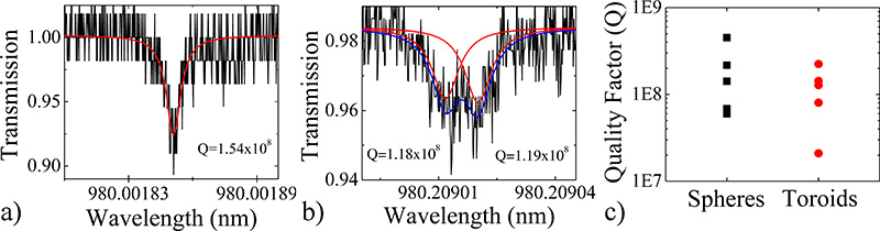
詳細なアプローチは、超高Qデバイスを作成していることを確認するには、我々はまた、線幅(Δλ)測定を実行し、ロードさを計算することによって、複数のデバイスのQ値の特徴を単純な式からQ:Q =λ/Δλ=ωτ、ここでλ=共振波長、ω=周波数、τ=光子寿命。以前に詳細な手順1,9と、複数のデバイスの比較グラフを用いて作製した各デバイスの代表的なスペクトルを図3に示します。すべてのデバイスの品質要因は、大半が億を超えていると、千万を超えています。
ミクロスフェアのスペクトルは、光が時計回りまたは反時計回りに伝播する光モードのいずれかに結合されていることを示す、単一の共鳴した。しかし、トロイドのスペクトルを同時に時計回りと反時計回りモードの両方に結合する光を示す、分割共振を示した。カップリングサイトでのわずかな欠陥がある場合にこの現象が発生します。デュアルローレンツにスペクトルをフィッティングすることにより、両方のモードのQ値を決定することができます。分割共振現象解明NAは球とトロイド共振器の両方で発生する可能性がありますが、それらは不完全に影響されやすいと球に比べて少ない光学モードを持っているとして、より頻繁にトロイドで観察される。

マイクロキャビティの作製プロセスの図1のフローチャート。 1)レンダリングと洗浄し、切断された光ファイバのb)の光学顕微鏡写真。 c)のレンダリング、d)の光学顕微鏡写真およびe)は共振器microspereの電子顕微鏡写真をスキャンします。

図2。microtoroid空洞製造プロセスのフロー· チャート。 )レンダリング、b)は、トップビュー光学顕微鏡写真およびc)のようなフォトリソグラフィーとBOEエッチングによって定義される円形の酸化パッドの電子顕微鏡写真をスキャンするサイドビュー。 BOEによって形成される酸化物のわずかなくさび形に注意してください。 d)のレンダリングは、e)トップビュー光学顕微鏡写真およびf)XeF 2エッチング工程後の酸化物パッドの電子顕微鏡写真をスキャンするサイドビュー。酸化ディスクがくさび形の外周部を保持していることに注意してください。 microtoroid空洞の電子顕微鏡写真をスキャンg)のレンダリング、h)は、トップビュー光学顕微鏡写真とi)のサイドビュー。

図3)。微小線幅測定法を用いて決定されるb)のmicrotoroid共振空洞の代表的な品質係数スペクトルを示す。非常に高いQのデバイスでは、一方の光が小さな欠陥をオフに反映しており、右回りと左回りの両方向で循環させるには、モード分割または二重ピークを観察することが可能です。 c)は、いくつかのフェアとmicrotoroid共振空洞のQ値を示す比較グラフは拡大図はここをクリック 。

図4:CO 2レーザリフローの模式セットアップ。 CO 2レーザビーム(青の実線)が反映し、サンプルに焦点を当てています。それは10.6ミクロン/ 10.6ミクロンを送信し、633 nmのを反映して633 nmのビームコンバイナ、通過します。ビームコンバイナのオフサンプルの光学カラムの画像は反射するので、イメージがやや赤です。このセットアップのために必要な部品のリストが表4である。

図5は誤って)ミクロスフェアおよびb)microtoroid共振空洞をリフロー。ビーム内の誤った配置のために、デバイスが形成されたMALです。 c)に不良マスクまたは貧しいリソグラフィーの結果として、トロイドは月形である。
ディスカッション
すべての光学構造と同様に、製造プロセスのあらゆる段階で清浄度を維持することは非常に重要です。リソグラフィおよび製造のトピックに書かれた多数の教科書があるので、以下の提案は包括的であるが、研究者が直面している多くの一般的な問題のいくつかを強調するものではありません。19から20
microtoroidの外周部の均一性は、初期ディスクの均一性によ?...
開示事項
利害の衝突が宣言されません。
謝辞
A.メーカーは、アネンバーグ財団大学院研究フェローシップによってサポートされていましたが、この仕事は国立科学財団[085281と1028440]によってサポートされていました。
資料
| Name | Company | Catalog Number | Comments |
| 部分の名前 | 会社 | カタログ番号 | コメント |
| ファイバスク | ニューポート | F-RFS | 任意の |
| 光ファイバ | ニューポート | F-SMF-28 | 光ファイバの任意のタイプを使用することができます。 |
| ファイバ被覆ストリッパ | ニューポート | F-STR-175 | ワイヤーストリッパーを使用することもできます |
| エタノール | 任意のベンダー | 溶剤レベルの純度 | メタノールまたはイソプロパノールで代替です。 |
表1微小球の作製材料。
| 試薬の名前 | 会社 | のカタログ番号 | コメント |
| 2μmの熱的に成長したシリカとシリコンウェーハ | WRS材料 | N / A | 我々は、<100>、4 "径の固有の8を使用して |
| HMDS(ヘキサメチルジシラザン) | アルドリッチ | 440191 | |
| フォトレジスト | シプリー | S1813 | |
| 開発者 | シプリー | MF-321 | |
| HFは、バッファ - 改良された | Transene | N / A | 改良された緩衝HFは、プレーンBOEまたはHFよりもエッチスムーズ、より良い品質を提供 |
| アセトン、メタノール、イソプロパノール | 任意のベンダー | 99.8%の純度 |
表2。MICRotoroid作製材料。
| 機器名 | メーカー | カタログ番号 | コメント |
| スピナー | Solitec | 5110-ND | すべてのスピナーを使用することができます。 |
| アライナ | ズース·マイクロテック | MJB 3 | すべてのアライナーを使用することができます。 |
| XeF 2エッチング | 高度な通信デバイス株式会社 | #ADCETCH2007 |
表3。Microtoroid製造装置。
| 部分の名前 | 会社 | カタログ番号 | コメント |
| CO 2 レーザー | Synrad | シリーズ48 | |
| 3軸ステージ | OptoSigma | 120-0770 | 同様に他のベンダーから入手できます。 |
| Siの反射1 "径) | II-VI | 308325 | 同様に他のベンダーから入手できます。 |
| キネマティックジンバルマウント(Siの反射のために) | トールラボ | KX1G | 同様に他のベンダーから入手できます。 |
| ビームコンバイナ(1 "径) | メラー光学 | L19100008-B0 | 同様に他のベンダーから入手できます。 |
| 4 "焦点距離のレンズ(1"径) | メラー光学またはII-VI | 他のベンダーから入手できるだけでなく、 | |
| 各種投稿、レンズマウント | トールLabsは、ニューポート、エドモンド·オプティクスまたはOptosigma | ||
| ズーム6000マシンビジョンシステム | Navitar社 | N / A | リアルタイムイメージングのための一般的なUSBカメラとコンピュータが必要です。これは、キットとして購入されています。 |
| ズーム6000システム用のフォーカサー | エドモンド·オプティクス | 54から792 | 同様に他のベンダーから入手できます。 |
| ズーム6000用XZ軸ポジショナ | パーカー巧みな | CR4457、CR4452、4499 | CR4457は、X軸、CR4452は、Z軸、4499は、ブラケットをマウントしているされています。 |
表4。CO 2レーザーリフロー詳細設定。
参考文献
- Armani, D. K., Kippenberg, T. J., Spillane, S. M., Vahala, K. J. Ultra-high-Q toroid microcavity on a chip. Nature. 421, 925-928 (2003).
- Gorodetsky, M. L., Savchenkov, A. A., Ilchenko, V. S. Ultimate Q of optical microsphere resonators. Optics Letters. 21, 453-455 (1996).
- Armani, A. M., Kulkarni, R. P., Fraser, S. E., Flagan, R. C., Vahala, K. J. Label-Free, Single-Molecule Detection with Optical Microcavities. Science. 317, 783 (2007).
- Choi, H. S., Ismail, S., Armani, A. M. Studying polymer thin films with hybrid optical microcavities. Optics Letters. 36, 2152-2154 (2011).
- Aoki, T. Observation of strong coupling between one atom and a monolithic microresonator. Nature. 443, 671-674 (2006).
- Hsu, H. -. S., Cai, C., Armani, A. M. Ultra-low threshold Er:Yb sol-gel microlaser on silicon. Optics Express. 17, 23265 (2009).
- Zhu, J. On-chip single nanoparticle detection and sizing by mode splitting in an ultrahigh-Q microresonator. Nature Photonics. 4, 46-49 (2009).
- Zhang, X., Choi, H. -. S., Armani, A. M. Ultimate quality factor of silica microtoroid resonant cavities. Applied Physics Letters. 96, 153304 (2010).
- Vernooy, D. W., Ilchenko, V. S., Mabuchi, H., Streed, E. W., Kimble, H. J. High-Q measurements of fused-silica microspheres in the near infrared. Optics Letters. 23, 247-249 (1998).
- Saleh, B. E. A., Teich, M. C. . Fundamentals of Photonics. , (2007).
- Ilchenko, V. S. Crystal quartz optical whispering-gallery resonators. Optics Letters. 33, 1569-1571 (2008).
- Soteropulos, C., Hunt, H., Armani, A. M. Determination of binding kinetics using whispering gallery mode microcavities. Applied Physics Letters. 99, 103703 (2011).
- Barclay, P. E., Srinivasan, K., Painter, O., Lev, B., Mabuchi, H. Integration of fiber-coupled high-Q SiNx microdisks with atom chips. Applied Physics Letters. 89, (2006).
- Srinivasan, K., Painter, O. Mode coupling and cavity-quantum-dot interactions in a fiber-coupled microdisk cavity. Physical Review. A. 75, (2007).
- Xu, Q. F., Lipson, M. All-optical logic based on silicon micro-ring resonators. Optics Express. 15, 924-929 (2007).
- Martin, A. L., Armani, D. K., Yang, L., Vahala, K. J. Replica-molded high-Q polymer microresonators. Optics Letters. 29, 533-535 (2004).
- Chao, C. Y., Guo, L. J. Polymer microring resonators fabricated by nanoimprint technique. Journal of Vacuum Science Technology B. 20, 2862-2866 (2002).
- Armani, A. M., Armani, D. K., Min, B., Vahala, K. J., Spillane, S. M. Ultra-high-Q microcavity operation in H2O and D2O. Applied Physics Letters. 87, 151118 (2005).
- Kovacs, G. T. A. . Micromachined Transducers Sourcebook. , (1998).
- Kovacs, G. T. A., Maluf, N. I., Petersen, K. E. Bulk Micromaching of Silicon. Proceedings of the IEEE. 86, 1536-1551 (1998).
転載および許可
このJoVE論文のテキスト又は図を再利用するための許可を申請します
許可を申請さらに記事を探す
This article has been published
Video Coming Soon
Copyright © 2023 MyJoVE Corporation. All rights reserved