Fabrication of a Low-Cost, Fiber-Coupled, and Air-Spaced Fabry-Pérot Etalon
In This Article
Summary
This protocol describes the construction of a low-cost, discrete, fiber-coupled, and air-spaced Fabry-Perot etalon with various applications, such as in trace-gas spectroscopy. The fabrication is possible in any facility with standard optical laboratory equipment available.
Abstract
Fabry-Pérot etalons (FPE) have found their way into many applications. In fields such as spectroscopy, telecommunications, and astronomy, FPEs are used for their high sensitivity as well as their exceptional filtering capability. However, air-spaced etalons with high finesse are usually built by specialized facilities. Their production requires a clean room, special glass handling, and coating machinery, meaning commercially available FPEs are sold for a high price. In this article, a new and cost-effective method to fabricate fiber-coupled FPEs with standard photonic laboratory equipment is presented. The protocol should serve as a step-by-step guide for the construction and characterization of these FPEs. We hope this will enable researchers to conduct fast and cost-effective prototyping of FPEs for various fields of application. The FPE, as presented here, is used for spectroscopic applications. As shown in the representative results section via proof of principle measurements of water vapor in ambient air, this FPE has a finesse of 15, which is sufficient for the photothermal detection of trace concentrations of gases.
Introduction
In its most basic form, an FPE consists of two plane-parallel partially reflecting mirror surfaces1. In the following explanations, when referring to mirrors, the optical substrate and the reflective coating are addressed as one. In most applications, the mirrors used feature one wedged surface2 to prevent unwanted etalon effects. Figure 1 illustrates the formation of the interference pattern of an air-spaced etalon (Figure 1A), as well as the reflectance function for different mirror reflectivities (Figure 1B).
The light enters the cavity through one mirror, undergoes multiple reflections, and leaves the cavity by reflection as well as transmission. As this article focuses on the fabrication of an FPE operated in reflectance, the further explanations refer to reflection specifically. The waves leaving the cavity interfere, depending on the phase difference, q = 4πnd/λ. Here, n is the refractive index inside the cavity, d is the mirror spacing, and λ is the wavelength of the interferometer's light source, here called the probe laser. A minimum reflectance occurs when the optical path difference matches the integer multiple of the wavelength,  . The finesse of an ideal plane-parallel etalon is determined by the mirror reflectivities R1 and R2 only3:

However, a real etalon is subject to many losses, which degrade the theoretically achievable finesse4,5,6. Deviation of the mirror parallelism7, non-normal incidence of the laser beam, beam shape8, mirror surface impurities, and scattering, among others, lead to a reduction in the finesse. The characteristic interference pattern can be described by the Airy function1:

The full width at half maximum (FWHM), as well as the free spectral range (FSR) of the reflectance function, can be calculated as follows:


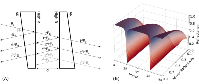
Figure 1: Fabry-Pérot interferometer theory. (A) A schematic depiction of the multi-beam interference for an air-spaced etalon with wedged windows. A plane wave, E0, enters the cavity under a certain angle, φ, through an anti-reflection (AR)-coated surface and subsequently undergoes multiple reflections between the highly reflecting (high R) surfaces spaced at a distance, d. With each reflection, part of the light is out-coupled of the etalon either in transmission or reflection, where it interferes with the other waves. (B) The reflectance function of an ideal Fabry-Pérot etalon for different mirror reflectivities (y-axis). Please click here to view a larger version of this figure.
FPEs can be found in a wide range of applications9,10,11. In the case presented here, the FPE is used in a photothermal interferometry (PTI) setup. In PTI, small density and, hence, refractive index changes, induced by the periodic excitation followed by the fast thermalization of a target gas via a second laser, are measured interferometrically12. The amount of heat and, thus, the magnitude of the refractive index change are proportional to the gas concentration. When measuring the intensity of the reflectance function of the FPE at its steepest point (operation point), these refractive index changes shift the reflectance function, thereby altering the measured intensity. As the reflectance function can be assumed to be linear in the region around the operation point, the measured signal is then proportional to the gas concentration. The sensor's sensitivity is determined by the slope of the reflectance function and is, therefore, proportional to the finesse. PTI, in combination with FPEs, has proven to be a sensitive and selective method to detect trace amounts of gases and aerosols13,14,15,16,17,18. In the past, many sensors for pressure and acoustic measurements relied on the use of moveable parts, like membranes, substituting the second mirror of the FPE19. Deflections of the membrane lead to a change in the mirror distance and, thus, the optical path length. These instruments have the disadvantage of being prone to mechanical vibrations. In recent years, the development of optical microphones using solid FPEs has reached a commercial level20. By abstaining from the use of moveable parts, the measurand changed from distance to the refractive index inside the Fabry-Pérot cavity, thus increasing the ruggedness of the sensors significantly.
Commercially available air-spaced FPEs cost beyond what is acceptable for prototyping and testing, as well as high-volume production instrument integration. Most scientific publications constructing and using such FPEs discuss the topic of fabrication only minimally21,22. In most cases, specific equipment and machines (e.g., clean rooms, coating facilities, etc.) are necessary; for example, for fully-fiber-integrated FPEs, special micromachining equipment is necessary. To reduce the manufacturing costs and enable the testing of multiple different FPE configurations to enhance their suitability for PTI setups, a new fabrication method was developed, which is described in detail in the following protocol. By using only commercially available, standard bulk-optic and telecom fiber-optic components, the manufacturing costs could be reduced to less than €400 euros. Every facility working with standard photonic equipment should be able to reproduce our fabrication scheme and adapt it to their applications.
Protocol
1. Three-dimensional printing of the measurement cell
- Adapt the measurement cell, as given in Supplementary Coding File 1, to your application. Three-dimensional-print the cell as well as the caps, given in Supplementary Coding Files 1-3, for mounting the bulk-optic materials.
NOTE: An SLA 3D printer was used for the present study (see Table of Materials). - While generating the print job, ensure to minimize the number of support structures inside the cavities and openings. Residual resin can reduce the diameter, and the bulk optics may become stuck.
- After printing, clean the cell with isopropyl alcohol, and remove all the support structures with a wire cutter and sandpaper.
- Thread the appropriate holes right after printing and before curing.
- Thread the gas inlet and outlet as M5 to mount the hose connector.
- Thread the central hole at the bottom as M4 for the post-mounting of the cell.
- Thread the smaller through-holes perpendicularly into the cage rod through-holes as M3 to allow the fixing of the cell to the cage system (Figure 2).
- UV-cure the cell (405 nm) and the caps at 60 °C for at least 40 min using a commercially available UV-curing device (see Table of Materials).
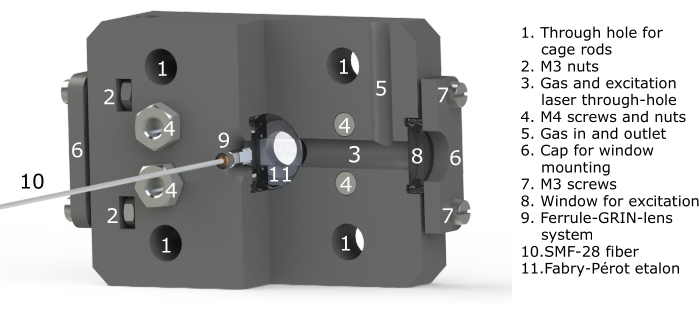
Figure 2: Labeled CAD model rendering of the measurement cell. A sectional view is provided here for more clarity. Please click here to view a larger version of this figure.
2. Preparing the spacers
- Cut two spacers out of one UV-fused silica (UVFS) precision window. Cut out two pieces of approximately 3 mm width from the precision window, as shown in Figure 3B.
NOTE: The spacers can be cut using a conventional low-cost glass cutter (see Table of Materials).
CAUTION: Wear gloves and protective glasses while cutting and handling the bulk optics. - Scribe a straight line onto the precision window with the cutter tool, and then break the glass using pliers. Always use pliers with flat surfaces, and put lens-cleaning tissues (or similar) between the metal and the glass in order to prevent damage to the glass surface.
- Clean the spacers with a duster spray to remove residual glass debris.
NOTE: Additionally, the spacers can be carefully wiped with lens-cleaning fluid as well as lens-cleaning tissues without applying pressure.
3. Assembly of the etalon
- Place the 3D-printed cell (step 1) on the table with the etalon pit facing upward.
- Insert an O-ring (10 mm x 1 mm, see Table of Materials) into the etalon pit, and press it slightly into the designated groove.
- Place the beamsplitter with the reflective surface facing upward in the etalon pit and onto the O-ring.
- Carefully place the two spacers onto the beamsplitter using a tweezer. Place them in a way that generates a clear aperture for the gas and excitation laser, which enters the air cavity via the through-hole running from one side of the cell to the other (Figure 2, number 3).
NOTE: The spacers must be placed on each side to obtain an air cavity in the middle, as shown in Figure 3B. Only grab the spacers on the side surfaces to avoid scratching the parallel surfaces. - When the spacers are in place, align the mirror on top of them, with the reflective side facing downward. The beamsplitter, spacers, and mirror have to be aligned concentrically now.
- Take the 3D-printed etalon cap, and put both O-rings (10 mm x 1 mm and 14 mm x 2 mm) into the designated grooves.
- Align the cap to the rectangular groove of the cell, and place it on top of the mirror.
- Apply pressure on the cap in order to fix the spacers in place. Lift the cell while always applying pressure on the cap, and insert four M4 screws through the designated holes from the back side.
- Mount them with four M4 nuts on the front side, and tighten them until the pressure from the cap is enough to hold the spacers in place and the O-rings are compressed enough.
- Check if the spacers are still in place; if so, the etalon is now ready for further use.
- Use the two additional 3D-printed caps to mount laser windows on the side of the measurement cell in order to make the cell gastight. Therefore, place an O-ring (10 mm x 1 mm) into the designated groove on the cell and another one (10 mm x 1 mm) onto the cap. Place the window in the groove, and fix the window cap with four M3 screws and nuts, as shown in Figure 2, number 2).

Figure 3: Rendering of the measurement cell and the FPE. (A) Rendering of the assembly process of the 3D-printed cell as well as the FPE with the corresponding mounting cap. (B) Rendering of the bulk-optic components in the correct order. The spacers create an air-spaced cavity between the two mirror surfaces. Please click here to view a larger version of this figure.
4. Assembly of the fiber-alignment platform
- Assemble the stages and adapter plates as listed in the Table of Materials. Use Figure 4 as orientation during the construction.
- Mount the first single-axis goniometric stage on an optical breadboard in the x-direction.
NOTE: Axis nomenclature was chosen arbitrarily. The optical breadboard plane is defined as an x-y plane, with the vertical direction facing out of the breadboard in a positive z-direction. - Depending on the stages used, mount an adapter plate on top of the goniometric stage, if necessary.
- Mount a two-axis x-y micrometer translation stage central on top of the adapter plate.
- Mount a right-angled bracket onto the translation stage facing in the y-direction.
- Mount a single-axis translation stage onto the right-angled bracket in the z-direction.
- Using additional adapter plates, mount the second goniometric stage in the z-direction on the translation stage.
- Attach a fiber ferrule clamp on top of a post. Choose the length of the post so that the fiber ferrule is exactly at the point of rotation of the second vertical goniometric stage. The distance is given in the stage's manual.
- The fiber ferrule's outer diameter is 2.8 mm. If no clamp for this diameter is available, use a 2.5 mm clamp, and widen it with a drill.
- Mount the post with the ferrule clamp on the second vertical goniometric stage in a z-position corresponding to the point of rotation of the first horizontal goniometric stage from step 4.2.
- Ensure that the ferrule sleeve and GRIN lens stick out of the ferrule clamp by a few millimeters in the negative z-direction.
- Choose the vertical position of the post so that the tip of the GRIN lens is at the goniometric stage's point of rotation.
- To mount the etalon, take a post, mount a right-angled bracket on it, and attach a standard SM1 threaded 30 mm cage plate on it. Mount four cage rods (>40 mm) on the plate facing in the positive z-direction.
- Take four metal springs with an inner diameter slightly larger than the cage rod's diameter, and place one on each cage rod. Slide the measurement cell with integrated FPE onto the rods with the beamsplitter side facing upward until it rests on the springs.
NOTE: Ensure that the cell can move freely in the z-direction. If the friction is too high, additional widening of the cell's through-holes for the cage rods is necessary. This is best done with a round file. - Mount the post, via a post holder, a base plate, and a clamping fork, just underneath the fiber alignment platform. Ensure that the opening of the cell, exposing the beamsplitter, is centered approximately 10 mm underneath the ferrule holder (step 4.5).
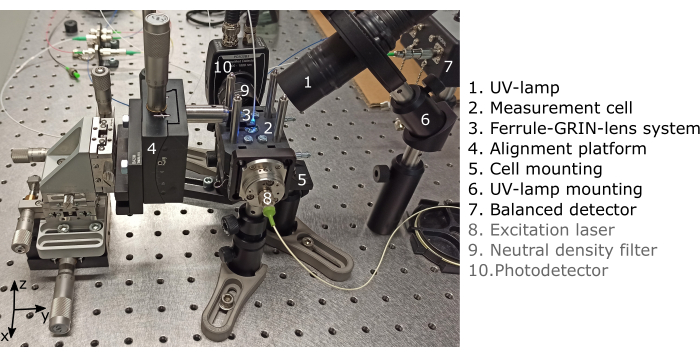
Figure 4: Picture of the alignment platform with the GRIN lens-coupled FPE during the UV-curing process. The components written in grey are for PTI measurements and are not necessary for the alignment process. Please click here to view a larger version of this figure.
5. Opto-electronic setup
- Assemble the optoelectronic components as listed in the Table of Materials, and arrange them as shown schematically in Figure 5.
- Mount the fiber optical components on an optical breadboard using the corresponding component trays.
- Mount the laser on a laser diode mount. Connect the laser source to a laser driver and TEC (thermoelectric cooler) controller with an integrated modulation function (triangular modulation); otherwise, an additional function generator is necessary.
- Set the triangular current modulation amplitude in a way that a wavelength range is covered that is well above the expected FWHM of the etalon (calculations can be found in the discussion section). Set the modulation frequency to around 100 Hz.
- Connect the optical output of the laser to the isolator input using L-bracket mating sleeves.
- Mount a 15 dB fiber-optic attenuator after the isolator, and connect it to the input port of the 1 x 2 coupler.
- Connect the coupler's output port with 90% optical power to port 1 of the optical circulator.
- Connect the coupler's output port with 10% optical power to the reference photodiode of the balanced detector.
- Connect port 2 of the circulator to the pigtailed ferrule-GRIN lens system.
- Connect port 3 to the signal photodiode of the detector.
- Set the balanced detector in "Auto-Balanced" mode. Connect the electrical "Signal" output of the detector to one channel of the oscilloscope with a BNC cable.
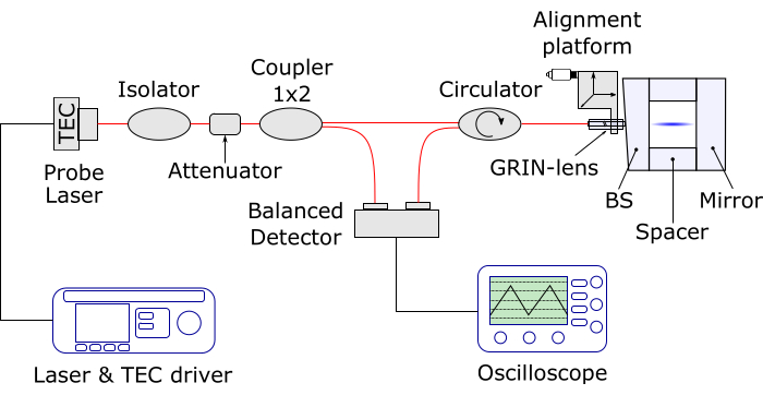
Figure 5: Schematic of the optoelectronic setup for the alignment procedure. The red lines represent optical fibers, the black lines are electronic cables, and the blue beam is the probe laser. A balanced detector is used here, but this can be replaced by a conventional photodetector. Therefore, the 1 x 2 coupler can be omitted. Please click here to view a larger version of this figure.
6. Fiber-GRIN lens alignment
- Mount the ferrule clamp on a post, and fix it via a post holder onto an optical breadboard.
- Fix the fiber ferrule sleeve into a ferrule clamp. As mentioned in step 4.6, widen the ferrule clamp with a drill if necessary.
- Fill a pipette with UV-curing adhesive (see Table of Materials).
CAUTION: Wear gloves and glasses while handling the bulk optics as well as the UV-curing adhesive. - Take the pigtailed fiber ferrule, and add a drop of adhesive on the side surface of the ferrule. Keep the front surface of the ferrule clean.
- Insert the ferrule into the ferrule sleeve. Ensure to insert the ferrule deep enough so the front end of the GRIN lens is at least 1-2 mm outside the ferrule sleeve.
- Apply a very quick pre-cure with a UV lamp (~10 s). Only shine the light from the back side (fiber end of the ferrule) to fix the ferrule to the sleeve without hardening any adhesive on the front end of the ferrule.
- Take the GRIN lens, and find the wedged side. This can be done with a microscope or by simply turning it. Thereby, the 8° wedged side becomes visible.
- Apply a drop adhesive onto the wedged end of the GRIN lens, and insert it into the ferrule sleeve.
NOTE: By applying slight pressure, the air leaves the cavity between the ferrule and the GRIN lens. There may be no air bubbles enclosed between the two surfaces. If there are, slight turning can help; otherwise, remove the GRIN lens, and repeat step 6.8. - Rotate the GRIN lens carefully until the two angled surfaces are parallel.
- Mount a beam analyzer approximately 150 mm in front of the GRIN lens. If no beam analyzer is available, a power meter with a pinhole in front can be used.
- Connect the pigtailed ferrule to a laser with the appropriate wavelength. Turn on the laser.
CAUTION: Laser safety precautions have to be taken. - Using tweezers, slightly move the GRIN lens out of the ferrule sleeve to change the distance between the ferrule and the GRIN lens. This distance is crucial for setting the focal length of the system. While moving the GRIN lens, constantly monitor the beam shape (or optical power).
NOTE: A short pre-cure (~ 10 s) can help if the alignment process is too unstable. - When the system is focused to the desired optimum, apply the final cure by exposing it to UV light for approximately 10 min.
- After curing, remove the ferrule sleeve from the clamp; at this point, it is ready for further use.
7. Fiber-etalon alignment
- Take the pigtailed ferrule and the GRIN lens system from step 5, and mount it with the ferrule clamp from step 4.5.
- Ensure that the translation stage in the z-direction is moved to its maximum height and that all the other stages are in neutral (centered) positions.
- Align the cell underneath it. Ensure that the GRIN lens points directly to the center of the opening. Fix the position of the cell at a height slightly below the GRIN lens (approximately 5 mm).
- Apply one or two drops of adhesive on the front end of the GRIN lens with the pipette.
- Lower down the translation stage in the z-direction until contact with the anti-reflection-coated surface of the beamsplitter is ensured. Continue to lower the GRIN lens until sufficient pressure is applied and the springs are under enough tension.
NOTE: This ensures that contact between the GRIN lens and the beamsplitter is maintained during the tilting process of the alignment. The amount of pressure necessary depends on the setup and can be adjusted during alignment if no reasonable reflectance function can be observed. Experience has shown that more pressure usually helps the alignment process. - Turn on the modulated laser as well as the oscilloscope. Ensure the oscilloscope has the highest possible resolution
 , when starting the alignment process. Set the time resolution so that two to three periods of the modulation are visible.
 - Start the alignment process by ensuring the GRIN lens points normally on the beamsplitter surface. This can be done by visual inspection and turning the goniometric stages accordingly. This is now the zero position.
- Step by step, deflect one goniometric stage slightly, and then move the other goniometric stage around the zero position.
- If no change can be observed on the oscilloscope, deflect the first goniometric stage slightly more, and repeat this iterative process until the triangular modulation becomes visible on the oscilloscope.
- If you observe a hysteresis of the signal after movements of the stages, check if all the components are fixed properly.
NOTE: An increase in pressure caused by moving the z-stage downward can also help. If the signal observed is not as strong as expected, the back reflection might come from one of the etalon's surfaces or one of the peripheral peaks of the reflectance function. As a rule of thumb, with a 70% beamsplitter and a fully reflecting mirror, the peak reflections observed are in the order of 25% of the optical power introduced into the etalon.
- Once a strong back reflection is observed, adjust the oscilloscope's resolution, and ensure the peak of the etalon's reflectance function sits central on the triangular modulation slopes (Figure 6). Tune the etalon's peak by changing the temperature of the laser until the peak is centered on the slope.
- Try to maximize the peak strength (minimum voltage) while simultaneously maximizing the peak-to-peak ratio of the triangular modulation by slight movements of the goniometric stages.
- When the alignment process is finished, mount the UV lamp close to the GRIN lens. Use a self-centering lens mount at an angle of 45°.
- Perform the curing stepwise. First, cure the adhesive that has already been applied in step 7.4. Keep monitoring the reflectance function on the oscilloscope. If the curing leads to a degradation of the alignment due to shrinkage of the adhesive, slightly adjust the goniometric stages.
- After 5-10 min, turn off the UV lamp, and apply more adhesive around the GRIN lens without touching it. Expose the adhesive to UV light for another 5-10 min. Repeat this step until the opening of the cell is completely filled with a homogenous layer of adhesive. Perform the final cure for more than 1 h.
- To ensure a proper connection of the glued components, either let the whole setup rest for 1 week or temper the adhesive joint at 60 °C for 1 h, if possible.
- Now, the ferrule sleeve can be removed from the clamp. Therefore, move the translation stage in a positive z-direction until the springs are fully relaxed. Avoid any stress on the ferrule-GRIN lens system; open the clamp, and remove it. Now, the etalon is finished and ready for further use.
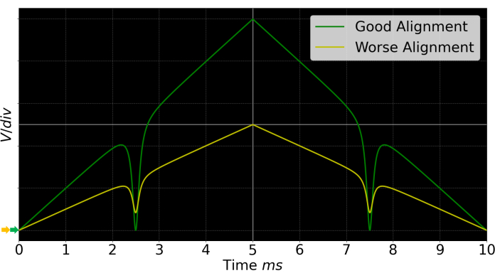
Figure 6: Exemplary, generic oscilloscope signal. In green, a good alignment is depicted, and in yellow, a worse one is shown. The better the alignment, the higher the peak-to-peak ratio of the triangular modulation, and the more the reflectance peak (valley) goes toward zero. Please click here to view a larger version of this figure.
8. Etalon characterization
- For the evaluation of the produced etalon, use the same fiber-optic setup as described in step 5. Use a measurement system capable of temperature tuning the laser stepwise and with a sufficient data logging rate.
NOTE: An FPGA-based system is used here (see Table of Materials). - Calculate the theoretical FSR. Depending on the laser used (see temperature tuning coefficient), perform a temperature sweep corresponding to at least two FSRs. Increase the temperature stepwise (increments of ~0.005 °C), and let the TEC settle for 2-3 s before measuring for another 2-3 s each time.
- Process the data with any numerical calculation program. Use any signal processing library with an integrated peak finder. The distance between two subsequent peaks represents the FSR. Calculate the FWHM by evaluating the width of the peak at its half height.
NOTE: As the calculation of FSR and FWHM is strongly dependent on the data format, no code is given here, but it can be made available by the author upon request. - Convert the temperature into wavelength by using the temperature tuning coefficient of the laser.
- Calculate the FSR as well as the FWHM from the measurements (Figure 7).
- Calculate the finesse of the fabricated FPE with the following formula:
 .
.
Representative Results
As can be seen in Figure 7, an FPE with a well-defined reflectance function could be fabricated.
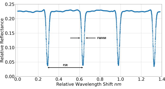
Figure 7: Measured reflectance function of the finished FPE. A temperature sweep, corresponding to a wavelength sweep of the laser, was performed to measure the reflectance function of the FPE. This is used to evaluate metrics like the full width at half maximum (FWHM) and the free spectral range (FSR) of the fabricated device. Relative reflectance refers to the relative proportion of light being back-reflected into the fiber after passing the FPE. Please click here to view a larger version of this figure.
The measured metrics of the FPE are listed in Table 1 and compared to the calculated values of an ideal etalon with the same specifications. The formulas for an ideal FPE can be found in the introduction section.
| Measured | Ideal FPE | |
| Finesse | 12.8 | 17.1 |
| FWHM | 0.0268 nm | 0.0234 nm |
| FSR | 0.3441 nm | 0.4004 nm |
| Sensitivity | 14 1/nm | 21 1/nm |
Table 1: Comparison of the measured and calculated metrics of the fabricated FPE etalon.
To validate the aptitude for a designated application, the FPE is used for PTI measurements of water vapor in ambient air. Therefore, an excitation laser with a wavelength of 1,364 nm is guided into the cell perpendicularly to the probe laser. Both lasers intersect inside the FPE. The excitation laser is modulated sinusoidally with a frequency of 125 Hz. By stabilizing the probe laser on the steepest slope of the FPE, via constant current, the highest sensitivity of the sensor is achieved. For water vapor measurements, the cell is operated with open windows and exposed to ambient air with a concentration of 13,762 ppmV, as measured by a reference device (temperature = 21.4 °C, pressure = 979.9 hPa, relative humidity = 52.2%). The signal is extracted by means of a fast Fourier transform (FFT) and compared to the background signal with the excitation laser turned off, as shown in Figure 8. A signal-to-noise ratio of more than 7,000 can be obtained, corresponding to a detection limit of approximately 5 ppmV (3σ).
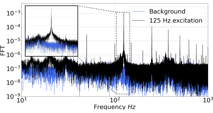
Figure 8: PTI measurements of water vapor in ambient air. In black, the FFT signal of a measurement with 125 Hz laser excitation is shown. In blue, the background signal without excitation is depicted. The inset shows the measured peak at 125 Hz in more detail. Please click here to view a larger version of this figure.
Supplementary Coding File 1: Measurement_cell.SLDPRT. CAD file for the measurement cell. The cell can be adapted to the requirements of the specific application and subsequently 3D-printed. Please click here to download this File.
Supplementary Coding File 2: cap_etalon.SLDPRT. CAD file for fixing the etalon inside the measurement cell. Please click here to download this File.
Supplementary Coding File 3: cap_window.SLDPRT. CAD file for fixing the laser windows onto the measurement cell. Please click here to download this File.
Discussion
As the FPE fabricated following the protocol given here is optimized for a specific application, possible adaptations and critical steps are explained in this chapter. First of all, the FPE and the measurement cell are designed for PTI measurements. Therefore, a gas inlet and outlet, as well as a channel for the excitation laser, which is perpendicular to the probe laser, are added to the cell. All the openings of the cell are either made air-tight via O-rings and/or covered via UVFS windows to allow laser propagation. If used differently, the cell, as given in Supplementary Coding File 1, can be redesigned and adapted to the specific application. The threading in step 1.4 is done post printing. The threads could also be 3D-printed, but as these tend to wear out fast, only holes with the appropriate core hole diameter are printed, and these are threaded afterward.
The choice of material for the spacers in step 2.1 is crucial. The parallelism of the spacers determines the parallelism of the etalon mirrors and, hence, influences the finesse7. A ½ inch UVFS precision window, as provided in the Table of Materials, with a parallelism of ≤5 arcsecs and a surface flatness of λ/10 over the clear aperture was used in this study. The coefficient of thermal expansion of UVFS is 0.55 x 10⁻⁶/°C. The temperature stability can be further increased by using, for example, Zerodur5 spacers, with a coefficient of thermal expansion lower than 0.1 x 10⁻⁶/°C; however, this has the disadvantage of higher costs.
The FPE is formed by one fully reflecting mirror, as well as a beamsplitter. The beamsplitter has one 70% reflecting surface, as well as an anti-reflective-coated back side. This enables the coupling of the light in and out of the etalon. Additionally, the beamsplitter's substrate features one wedged side to prevent unwanted etalon effects. The back side of the mirror is roughened for the same reasons.
In step 5.1, the optoelectronic setup for tracking the alignment process is described. All the fibers used are standard SMF-28 fibers with FC/APC connectors. Due to the designated application for PTI, a balanced photodetector was readily available in this study, but this is not necessary in general. A conventional photodetector can be used instead; in this case, using a 1 x 2 coupler is obsolete. These changes do not affect the other components of the setup, as presented in Figure 5. The triangular current modulation of the probe laser, as described in step 5.4, corresponds to a wavelength sweep. A current range sufficient to sweep over at least one reflectance peak of the FPE has to be chosen. Therefore, one FSR can serve as a rule of thumb. Calculations for the FSR of an ideal FPE can be found in the introduction section. Together with the current tuning coefficient (nm/mA) of the laser, given in the respective manual, the current range covering one FSR can be calculated. As an example, the laser used in this work had a current tuning coefficient of 0.003 nm/mA and emitted at a wavelength of 1,550 nm. The expected FSR of an ideal FPE with 3 mm mirror spacing, d, is approximately 0.4 nm. This gives a current tuning range of 133 mA.
In this work, the modulation frequency was set to 100 Hz for convenient display at the oscilloscope. As the desired current tuning range is rather large, a fixed-fiber attenuator can be used to remain within the power limits of the used detector. The attenuator can be mounted directly after the isolator.
The UV-curing adhesive used in step 6 and step 7 is transparent to laser light and has a refractive index of 1.56. The alignment process, as described in step 7.1, is dependent on the available photodetector. The balanced detector used in this setup generates a negative voltage "Signal" output. For reasons of generality, a positive voltage output is assumed for the description of step 7.10 and in Figure 6. For a well-aligned etalon, the reflectance peak will go toward zero, while the triangular function will increase its peak-to-peak ratio.
For the etalon characterization in step 8.1, numerical calculation software is used (see Table of Materials). The measured voltage for each temperature step is averaged and plotted, as shown in Figure 7. To convert the temperature steps into wavelength steps, the temperature tuning coefficient of the probe laser is used. Signal analysis libraries have integrated peak-finding algorithms, which can be used for that purpose. As the data analysis strongly depends on the data format, no code is provided here, but it can be made available by the corresponding author upon request.
A possible limitation of the fabrication technique presented here is the thermal and mechanical stability in changing environments. As the scope of this instructional paper is the low-cost prototyping of FPEs for laboratory applications, no tests concerning mechanical and temperature stability are given here. If the FPE is used for mobile applications or in changing environments, additional measures have to be taken in order to mechanically stabilize the fiber-GRIN lens system relative to the etalon.
A new method to fabricate and characterize an FPE is demonstrated here with standard optical components available in every photonic laboratory. The presented FPE has a finesse of approximately 15 and a sensitivity sufficient for detecting approximately 5 ppmV of water vapor. Besides the presented application for PTI, this FPE could be used in applications such as building optical microphones20, which are commonly applied in the field of non-destructive testing23, refractive index measurements24,25, or hygrometers26, just to name a few.
Disclosures
There are no conflicts of interest.
Acknowledgements
The work presented here was conducted in the framework of the FFG funded project "Green Sensing" and the NATO SPS program "Photonic Nano Particle Sensors for Detecting CBRN events". The work was also supported by TU Graz Open Access Publishing Fund.
Materials
| Name | Company | Catalog Number | Comments |
| Auto-Balanced Photoreceiver Nirvana | New Focus, Inc. | 2017 | Balanced Photodetector |
| Benchtop laser diode/TEC controller, 1A/96 W | Thorlabs | ITC4001 | |
| Butterfly laser diode mount | Thorlabs | LM14S2 | |
| Clamping fork | Thorlabs | CF175 | |
| compactRIO | National Instruments | For data aquisition | |
| Dust remover | RS Components | 168-1644 | |
| FC/APC to FC/APC Single L-Bracket Mating Sleeve | Thorlabs | ADAFCB3 | Multiple needed |
| Fiber cleaning fluid | Thorlabs | RCS3 | |
| Fiber optic SM circulator | AFW technologies | CIR-3-15-L-1-2 | |
| Fiber optic SM coupler 1 x 2, 90/10 | AFW technologies | FOBC-1-15-10-L-1-S-2 | Only if balanced photodetector is used |
| Fiber optic SM isolator | AFW technologies | ISOD-15-L-1-2 | |
| Fiber optic storage reels | Thorlabs | FSR1 | Multiple needed |
| Fixed fiber optic attenuator | Thorlabs | FA15T-APC | Different attenuation levels used |
| GRIN/Ferrule Sleeve, 1.818 mm Internal Diameter, 10 mm Length, Borosilicate Glass | Thorlabs | 51-2800-1800 | Fiber-GRIN-lens system |
| GRIN Lens, Ø1.8 mm, 0.23 Pitch, 8°, 1560 nm Design Wavelength, AR Coated: 1250 - 1650 nm | Thorlabs | GRIN2315A | Fiber-GRIN-lens system |
| Handheld UV-LED lamp | RS Components | 220-6819 | Lamp for curing the adhesive |
| High precision stage and base | Newport | 9062-X-M | Three nedded |
| Hose conector | RS Components | M5 threaded | |
| Large Goniometer, 44.5 mm Distance to Point of Rotation, ±5°, Metric | Thorlabs | GNL18/M | Two needed |
| L-Bracket Mating Sleeve | Thorlabs | ADAFCB3 | |
| Magnetic button clamps | Thorlabs | BM075 | Multiple needed |
| Micrometer screw | Newport | 9355 | Three nedded |
| MIL-A-3920 Optical Adhesive with Resiliency, 1 oz. | Thorlabs | NOA61 | UV-curing adhesive |
| Mounting Base, 50 mm x 75 mm x 10 mm | Thorlabs | BA2/M | |
| O-Rings | Haberkorn | Sizes given in text | |
| Passive component fiber tray | Thorlabs | BFCT | Multiple needed |
| Pedestal base adapter | Thorlabs | BE1 | |
| Pigtailed Ferrule, Ø1.8 mm, 8°, FC/APC, AR Coated: 1310/1550 nm | Thorlabs | SMPF0115-APC | Fiber-GRIN-lens system |
| Post holder | Thorlabs | PH30/M | |
| Post-Mountable Ø2.5 mm Ferrule Clamp, M4 Tap | Thorlabs | FCM/M | |
| Python | Python | 3.9 | Numerical data analysis software |
| Right-angled-bracket | Newport | 9062-A-M | |
| Self-centering lens mount | Thorlabs | SCL03 | |
| Silberschnitt 3001 | Bohle | 3001 | Glas cutter set |
| SM1-threaded standard cage plate | Thorlabs | CP33/M | |
| UV-curing device | Formlabs | Form Cure | |
| 1550 nm 20 mW butterfly DFB laser diode | AeroDiode | 1550LD-5-0-0-2 | |
| 3D-printer | Formlabs | 3+ | |
| Ø1/2" UVFS Broadband Precision Window, Uncoated, t = 3 mm | Thorlabs | WG40530 | Spacers |
| Ø1/2" Broadband Dielectric Mirror, 1280 - 1600 nm | Thorlabs | BB05-E04 | Mirror |
| Ø1/2" 70:30 (R:T) UVFS Plate Beamsplitter, Coating: 1.2 - 1.6 µm, t = 3 mm | Thorlabs | BST06 | Beamsplitter |
References
- Vaughan, M. . The Fary-Pérot Interferometer. History, Theory, Practice, and Applications. , (1989).
- Liu, M., Chao, X., Ye, Z. Transmitting intensity distribution after a Gaussian beam incidenting nonnormally on a wedged Fabry-Pérot cavity. Optik. 119 (14), 661-665 (2008).
- Ismail, N., Kores, C. C., Geskus, D., Pollnau, M. Fabry-Pérot resonator: Spectral line shapes, generic and related Airy distributions, linewidths, finesses, and performance at low or frequency-dependent reflectivity. Optics Express. 24 (15), 16366-16389 (2016).
- Eklund, E. J., Shkel, A. M. J. Factors affecting the performance of micromachined sensors based on Fabry-Perot interferometry. Journal of Micromechanics and Microengineering. 15 (9), 1770-1776 (2005).
- Rees, D., Fuller-Rowell, T. J., Lyons, A., Killeen, T. L., Hays, P. B. Stable and rugged etalon for the Dynamics Explorer Fabry-Pérot interferometer. 1: Design and construction. Applied Optics. 21 (21), 3896-3902 (1982).
- Killeen, T. L., Hays, P. B., Kennedy, B. C., Rees, D. Stable and rugged etalon for the Dynamics Explorer Fabry-Pérot interferometer. 2: Performance. Applied Optics. 21 (21), 3903-3912 (1982).
- Marques, D. M., Guggenheim, J. A., Munro, P. R. T. Analysing the impact of non-parallelism in Fabry-Pérot etalons through optical modelling. Optics Express. 29 (14), 21603-21614 (2021).
- Marques, D. M., et al. Modelling Fabry-Pérot etalons illuminated by focussed beams. Optics Express. 28 (5), 7691-7706 (2020).
- Islam, M. R., Ali, M. M., Lai, M. -. H., Lim, K. -. S., Ahmad, H. Chronology of Fabry-Perot interferometer fiber-optic sensors and their applications: A review. MDPI Sensors. 14 (4), 7451-7488 (2014).
- Preisser, S., et al. All-optical highly sensitive akinetic sensor for ultrasound detection and photoacoustic imaging. Biomedical Optics Express. 7 (10), 4171-4186 (2016).
- Chen, J., et al. Micro-fiber-optic acoustic sensor based on high-Q resonance effect using Fabry-Pérot etalon. Optics Express. 29 (11), 16447-16454 (2021).
- Bialkowski, S. E., Astrath, N. G. C., Proskurnin, M. A. . Photothermal Spectroscopy Methods. , (2019).
- Campillo, A. J., Petuchowski, S. J., Davis, C. C., Lin, H. -. B. Fabry-Pérot photothermal trace detection. Applied Physics Letters. 41 (4), 327-329 (1982).
- Breitegger, P., Lang, B., Bergmann, A. Intensity modulated photothermal measurements of NO2 with a compact fiber-coupled Fabry-Pérot interferometer. MDPI.Sensors. 19 (15), 1424 (2019).
- Waclawek, J. P., Kristament, C., Moser, H., Lendl, B. Balanced-detection interferometric cavity-assisted photothermal spectroscopy. Optics Express. 27 (9), 12183-12195 (2019).
- Pevec, S., Donlagic, D. Miniature all-fiber Fabry-Pérot sensor for simultaneous measurement of pressure and temperature. Applied Optics. 51 (19), 4536-4541 (2012).
- Dudzik, G., Krzempek, K., Abramski, K., Wysocki, G. Solid-state laser intra-cavity photothermal gas sensor. Sensors and Actuators B: Chemical. 328, 129072 (2021).
- Chen, J., et al. Micro-fiber-optic acoustic sensor based on high-Q resonance effect using Fabry-Pérot etalon. Optics Express. 29 (11), 16447-16454 (2021).
- Hälg, B. A silicon pressure sensor with a low-cost contactless interferometric optical readout. Sensors and Actuators A: Physical. 30 (3), 225-230 (1992).
- Fischer, B. Optical microphone hears ultrasound. Nature Photonics. 10 (6), 356-358 (2016).
- Waclawek, J. P., Bauer, V. C., Moser, H., Lendl, B. 2f-wavelength modulation Fabry-Pérot photothermal interferometry. Optics Express. 24 (25), 28958-28967 (2016).
- Chen, J., et al. Acoustic performance study of fiber-optic acoustic sensors based on Fabry-Pérot etalons with different Q factors. MDPI Micromachines. 13 (1), 118 (2022).
- Meyendorf, N., Ida, N., Singh, R., Vran, J. . Handbook of Nondestructive Evaluation 4.0. , (2022).
- Kim, Y. J., Celliers, P. M., Eggert, J. H., Lazicki, A., Millot, M. Interferometric measurements of refractive index and dispersion at high pressure. Scientific Reports. 11, 5610 (2021).
- Stollberger, W. F. Single particle photothermal interferometry. Technical University Graz. , (2022).
- Radeschnig, U., Bergmann, A., Lang, B. Flow-enhanced photothermal spectroscopy. MDPI Sensors. 22 (19), 7148 (2022).
This article has been published
Video Coming Soon
JoVEについて
Copyright © 2023 MyJoVE Corporation. All rights reserved