Harwellの結晶化施設とダイヤモンド光源Beamline VMXiを用いた結晶化とその 場 室温データ収集
要約
ハーウェル研究施設の結晶化施設を使用したタンパク質の結晶化のプロトコルと、その後のダイヤモンドの多用途高分子結晶構造解析in situ(VMXi)ビームラインでのプレート内の結晶からのその場X線結晶学的データ収集を紹介します。サンプル要件、結晶化プロトコル、およびデータ収集ガイドラインについて説明します。
要約
ハーウェルの結晶化施設を使用したロボットタンパク質結晶化のプロトコルと、ダイヤモンド光源ビームラインVMXiの結晶化プレートからの その場 室温データ収集について説明します。このアプローチにより、複数の結晶から高品質の室温結晶構造を簡単に決定でき、結晶化試験の結果を非常に迅速にフィードバックできるだけでなく、連続結晶構造解析が可能になります。タンパク質の構造、リガンド結合、およびダイナミクスを理解する上での室温構造の価値は、構造生物学のコミュニティでますます認識されるようになっています。このパイプラインは、複数のアクセスモードを使用して、世界中のユーザーがアクセスできます。セットアップされた結晶化実験は、機械学習ツールを使用して自動的に識別された結晶を使用して、リモートで画像化および表示できます。データは、プレート内のユーザーが選択した結晶から最大60°回転するデータセットを備えたキューベースのシステムで測定されます。特定のウェルまたはサンプルグループ内のすべての結晶からのデータは、xia2.multiplexを使用して自動的にマージされ、出力はWebブラウザインターフェイスを介して直接アクセスできます。
概要
X線結晶構造解析は、タンパク質の構造と機能を理解するための重要なツールであり、タンパク質やその複合体と基質や薬剤候補などの高分解能構造を提供します。しかし、多くの場合、望ましい特性(回折性が高く、浸漬に適し、双晶などの結晶病理を伴わない結晶形態)を得ることは、依然としてかなりのボトルネックとなっています1。タンパク質結晶を製造するのに適した化学条件は一般に予測できないため、何千もの潜在的な化学混合物を探索する結晶化スクリーニングが標準であり、多くの場合、記録された結晶化滴画像を監視するためのスクリーニングとクリスタルホテルを設定する自動化/ロボット工学の支援を受けます。
結晶が現れたら、通常、ナイロンまたはカプトンループを使用して結晶化環境から回収し、凍結保護剤を含む液滴に移してから、液体窒素に沈没凍結する必要があります。結晶化とX線データ収集の間のこれらの追加ステップには、密閉環境が破壊されたときの結晶化滴の脱水、取り扱い時の結晶への機械的ストレス、および結晶格子への凍結保護剤による損傷(通常、モザイク拡散の増加)などの要因が含まれる可能性があります2.さらに、結晶の採取には時間と労力がかかり、特に採取プロセス中に液滴に皮膚が形成された場合、サンプル間の不均一性につながる可能性があります。VMXiビームラインは、プレートに付着した結晶から、データ収集のために廃棄される使用可能なデータへのアクセスを提供します。
X線の結晶構造の大部分は、上記のアプローチを使用して100Kで決定されるため、結晶の輸送と取り扱いが容易になり、X線ビームの結晶寿命が桁違いに長くなります。しかし、非極低温条件下、つまりタンパク質機能に関連する生理学的条件にはるかに近い下で構造を決定することへの関心が高まっています2,3,4。これにより、タンパク質の動的構造をよりよく理解し、機能的に関連性のない状態で凍結するアミノ酸コンフォメーションやループを回避し5、細胞や生物内のタンパク質の自然環境6にはるかに近い条件下でリガンド結合を探索することができます。
英国のダイヤモンド光源シンクロトロンの多用途高分子結晶構造解析in situ(VMXi)ビームラインで実施されている別のアプローチは、結晶が成長した環境(つまり、結晶化プレート内)で、周囲条件下で、外乱なしに結晶から直接回折データを測定することです7,8。.これにより、結晶化スクリーニングと最適化からの非常に迅速なフィードバックが可能になり、ユーザーを要件に最適な結晶形に導きます。また、高品質の室温構造を自動化して製造することもできます9。
このプロトコルは、ユーザーが結晶化の準備ができている高純度のタンパク質サンプルを持っていることを前提としています。本稿では、ハーウェルの結晶化施設にアクセスしてタンパク質結晶を作製し、ビームラインVMXiを使用してデータ収集を行うユーザーエクスペリエンスについて説明します(図1)。
ハーウェルの結晶化施設
ハーウェル(CF)の結晶化施設は、ダイヤモンド光源に隣接するハーウェル(RCaH)の研究施設にあります。この施設は、結晶化スクリーニング、結晶最適化、結晶イメージング、および特性評価にロボットを使用して、高分子結晶化のためのハイスループット自動ラボをユーザーに提供します。高度に自動化されたVMXiビームラインとの緊密な統合により、室温構造の決定ペースが大幅に加速し、非極低温条件下で、新しいタンパク質構造、タンパク質-リガンドおよびDNA-リガンド複合体の特性評価、および自動フラグメントスクリーニング(図1)が可能になりました。
CFパイプラインは、可溶性タンパク質および膜タンパク質の結晶化のためのナノリットル結晶化ロボット9 、市販の結晶化スクリーニングおよび複雑なカスタム最適化スクリーニングを調製するためのリキッドハンドリングロボット、および結晶化プレートのイメージング用の4つのイメージング装置(4°Cで1台、20°Cで3台)を含む一連の装置です( 材料表を参照)).1台のイメージャーは脂質立方晶相(LCP)ガラス板のイメージングが可能で、もう1台のイメージャーは多蛍光光学系(いずれも20°C)を備えています。
この施設は現在、膜タンパク質研究所(MPL;https://www.diamond.ac.uk/Instruments/Mx/MPL.html)、XChemフラグメントスクリーニング施設 10、MXビームライン、XFELハブ、ならびにRosalind Franklin Institute(RFI)。この確立され最適化されたパイプラインにより、幅広い構造生物学プロジェクトで結晶化実験を実施することができました。このホワイトペーパーでは、VMXiでのデータ収集を目的とした結晶のパイプラインについて説明しますが、結晶を採取してクライオ冷却したり、XChemパイプラインに送ったりすることもできます。
ユーザーアクセスはダイヤモンドMXプロポーザルシステム(https://www.diamond.ac.uk/Instruments/Mx/Synchrotron-Access.html)を通じて割り当てられ、産業ユーザーはダイヤモンド業界リエゾングループを通じてサポートされます。すべてのユーザーは、手作業で輸送できるサンプルまたはプレートを持って現場に来ることができます。私たちの経験では、液滴が分配された場所から遠ざかったり、結晶化リザーバーによって滴が損傷したりする可能性があるため、宅配便でプレートを送ることはお勧めしません。また、ユーザーは、タンパク質サンプルをCFに送り、スタッフが代理で結晶化実験を行うこともできます。実験は、CFの場合はRock Maker Webにログオンするか、VMXiの場合はISPyBを介して、ユーザーがリモートで監視できます。CFへのアクセスは、Diamondで収集されたX線回折結果に基づいて反復的に実行できます。
ダイヤモンド光源ビームラインVMXi
ビームラインVMXi(以下、ビームライン)は、室温で高度に自動化されたX線結晶構造解析装置で、適切な結晶化プレート内の結晶からのデータ測定に重点を置いた、最近開発されたユニークな装置です。このビームラインは、マイクロフォーカス(10 x 10 μm)、ピンクビーム(バンドパス<5 × 10⁻²ΔE/E)で、~2 ×10 13 光子/秒(16 KeV時)の高フラックスを提供します7。この高フラックスビームは、高速検出器と相まって、サンプルの非常に高いスループットと、10 μm以上のサイズのサンプルからのデータ収集を可能にします。
結晶化プレートは、ISPyB11 インターフェースSynchWeb12を使用してプレートを登録しながら、サンプルストレージシステムに保管され、ユーザーから提供されたスケジュールに基づいてイメージングされることでビームラインに入ります。通常、ユーザーはイメージング用の時点のフィボナッチ数列(0、12、24、36、60...プレートがシステムに挿入されてから7,320時間)。プレートが画像化されると、ユーザーに電子メールで通知されます。可視光とUV光の両方のイメージングは、ユーザーがオンデマンドで利用できます。サンプルストレージシステムによって撮影された画像は、機械学習アルゴリズムによって分析されます。これにより、結晶に似たオブジェクトの関心のあるポイントが自動的に特定され、ユーザーがデータ収集のためにキューに追加できる関心のあるポイントが登録されます。ユーザーは、可視光画像を手動でクリックして関心のあるポイントを登録したり、ラスタースキャンで分析する領域をクリックしてドラッグしたりすることもできます。これらのポイントは、自動的に配置されたポイントと一緒にキューに追加できます。
すべてのサンプルがデータ収集に適したパラメーターを持つと、プレートはキューに入ります。プレートがキューの一番上に到達すると、自動的にビームラインに分注されます。結晶化プレートは、ロボットアームによって結晶ホテルからビームラインに自動的にロードされ、画像マッチングに続いて、ユーザー定義の指示に従って、選択した各結晶から最大60°回転の結晶学的データセットが測定されます。プレート内のすべての液滴は、ビームライン上でのこれらの実験に使用できます。複数の結晶からデータをマージして、同型で最適にマージされたデータセットを自動化された方法で生成します7,9。キューに入れられたすべてのデータセットが収集されると、他のDiamond MXビームラインと同様に、ISPyB11でデータセットを表示するためのリンクが記載された電子メールがユーザーに送信されます。また、ビームラインのWebページ(https://www.diamond.ac.uk/Instruments/Mx/VMXi.html)にも移動します。
プロトコル
1. Harwellの結晶化施設を使用した in situ プレート内の結晶の生成
注: CF へのアクセスは、プロジェクトのアプリケーションとユーザー タイプ (アカデミックまたは業界) によって異なります。XChemおよびMPLプロジェクトには、ユーザー管理システム(UAS)を介した独自の提案申請システムがあり、標準アクセスルート(iNEXT DiscoveryおよびEUbOPENを含む)またはBAGアクセスを介して提出できます。以下のプロトコルは、VMXi ユーザーに固有のものです。
- 提案書の提出と訪問の準備
- プロジェクトに関する情報を BAG プロポーザル アプリケーションに提供するか、アクティブな BAG プロポーザルに追加します。通常、事務処理を整理するBAGコーディネーターがいます。または、ビームラインへのアクセスのための迅速なアクセス提案を提出してください。
- 宅配便または直接現場に到着する前に、サンプルがUASに登録され、提案書の安全性が検証されていることを確認してください。
- ユーザーが (FedID とパスワードで) 登録されていることを確認します。
- ユーザーが BAG コーディネーターによって UAS のアソシエイトとして MX プロポーザルに追加されていることを確認します。
- ビームライン結晶化試料詳細フォームに必要事項を記入し、VMXi@diamond.ac.uk に送付してください。
- ビームラインのスタッフと実験の必要条件やビームラインの空き状況について連絡を取り合う。
- タンパク質サンプルを出荷する場合は、事前の手配によってのみサンプルをお送りください。詳細については、セクション 1.2 を参照してください。
- ユーザーがCFに結晶化プレートを設置するために現場に来る場合は、施設の機器を使用する時間帯の空き状況について施設のスタッフに確認し、セクション1.2.1に従ってください。
- ユーザーがプレートを現場に持ち込む場合は、サンプルが正しいプレートタイプに分注され、結晶化滴を正しい場所と量に配置してください。セクション 1.2.2 に従ってください。ビームラインは、特異的な in situ結晶化プレート(Greiner CrystalQuickXおよびMiTeGen In Situ-1)のみを受け入れます。液滴が200nL以下であることを確認してください。
- CFでの結晶化実験
注:この施設では、蒸気拡散や、オイルやLCP下でのバッチ結晶化など、多くのハイスループット高分子結晶化法を提供しています。70-100 μLの純粋なタンパク質から始めて、100 nLのタンパク質溶液と100 nLの結晶化リザーバー溶液の比率を使用し、プレートを20°Cでインキュベートして、3つのスクリーンで可溶性タンパク質の蒸気拡散実験を行うことをお勧めします。 施設内には多くの業務用スクリーンが設置されています。湿度と温度の制御は、4°Cと20°Cが最もよく使用されます。CFを訪問するユーザーは、標準化されたトレーニングを受け、結晶化装置の操作をサポートし、ここで説明する設定を使用します。- CFでセットアップするためのサンプルの出荷
注:現場に到着する前に、タンパク質サンプルはUASシステム内の提案書で検証されている必要があります。タンパク質サンプルが現場に到着すると、スタッフのメンバーは、ユーザーとの以前のコミュニケーションで指示されたように結晶化実験を設定します。確認書は、実験用結晶化プレートのバーコード情報を記載した電子メールで送信されます。ユーザーは、結晶化プレートを容器として関連する提案に追加するよう求められます。これが完了すると、プレートは結晶化施設またはビームラインの自動イメージャーに保管できます。ISPyBは、ビームラインでの相互作用に使用されるインターフェースです。- 結晶化のための濃度のタンパク質サンプル溶液を25 μLのアリコートの倍数で提供します。タンパク質サンプルを含むサンプルチューブに明確にラベルを付けます。
- 必要に応じて、タンパク質緩衝液、リガンド溶液、またはリザーバー溶液を用意します。
- どのスクリーンとドロップ率を使用すべきかを施設スタッフに伝えます。
- 結晶化プレートの設定
注:Greiner CrystalQuickX および MiTeGen In Situ-1 プレートの結晶化滴は、特定の場所に配置する必要があります。他の場所でセットアップされたプレートは、ここで説明する次のMosquito13 設定を使用する必要があります。- MiTeGen In Situ-1 のプレート定義を調整するには、Mosquito SPT ソフトウェアを開き、設定 | 96ウェル |MiTeGen In Situ-1(96 x 2滴)(図2A)。編集ボタンをクリックし、サブウェル 2 の位置の値を修正します: X オフセットを - 1.2 に、Y オフセットを 1.8 に、サブウェル 3 の位置: X オフセットを 1.3 に、Y オフセットを 1.8 に修正します(図 2B、C)。
- Greiner CrystalQuickXのプレート定義を調整するには、Mosquito SPTソフトウェアを開き、設定 | 96ウェル |Greiner CrystalQuickX(図2D)。編集ボタンをクリックし、サブウェル 1 の位置の値を修正します: X オフセットを - 1.95 に、Y オフセットを 1.45 に、サブウェル 2 の位置の X オフセットを 1.95 に、Y オフセットを 1.45 に修正します(図 2E、F)。
- CFでセットアップするためのサンプルの出荷
2. ダイヤモンド光源のビームラインの利用
注:ユーザーによるビームラインとのやり取りはすべて、ISPyB11 インターフェースを使用してリモートで行われます。ビームラインに物理的に立ち会う必要はなく、データは特定の時間にスケジュールされるのではなく、キューベースのシステムを使用して収集されます。ユーザーには、ダイヤモンド光源へのアクセスに関連付けられた提案書があります。ビームラインでは、各結晶化プレートに固有の訪問が割り当てられ、100 Kのサンプルを含むパックに類似したISPyB11 内の「コンテナ」として定義されます。 最適化画面はSynchWebインターフェースを使用して作成できないため、通常はコメントセクションに情報が追加されます(ステップ2.1.4を参照)。プレートの所有者は、イメージングに関する電子メールとプレートの完了通知を受け取るため、プレートを登録する個人は電子メールアドレスを確認する必要があります。
- プレートの登録
- 適切なダイヤモンドFedIDでISPyBにログインし、[プロポーザル]を選択します。スクロールするか、検索バーに提案番号を入力して、関心のある提案を検索します。プロポーザル番号(図3A)の下のドロップダウンメニューから[出荷]を選択すると、[出荷]ウィンドウが開き、そのプロポーザルの出荷が表示されます。右上の[+納品の追加]をクリックして[新しい納品の追加]ウィンドウを開き、納品に名前を付けて[自動/イメージャー]をクリックし、左下の[納品の追加]ボタンをクリックします(図3C)。
- 出荷ウィンドウ(図3D)で[ +Add Container]をクリックすると、[ Add container ]ページビューが表示されます(図3E)。[ コンテナタイプ] ドロップダウンメニューで、関連するプレートタイプのいずれかを選択します。ページは、選択したコンテナタイプを反映するように変更されます。 バーコード と 容器名 は、実験プレートに固有のビームラインスタッフからの電子メールの指示に従って入力してください。大文字と小文字が区別されることに注意してください。
- [Requested Imager]ドロップダウンメニューから[VMXi 20 °C imager]を選択し、[Imaging Schedule]ドロップダウンメニューから[Fibonacci imaging schedule]を選択し、[Crystallization Screen]ドロップダウンメニューから結晶化画面、[Owner]ドロップダウンメニューからユーザー名を選択し、[View]ボタンをクリックして、[Email]ボックスに正しい連絡先の電子メールアドレスを入力します(図3F)。
- プレートの詳細を [コメント] ボックスに入力します。 [Protein ]ドロップダウンメニューから関連するサンプルを選択し、UASに登録され、Diamond社が承認した頭字語を実験計画書に使用します。[ サンプル名 ] ボックスに同じ名前を入力します。残りのボックスは空のままにします。
- +プレートアイコンをクリックすると、プレート全体にサンプルが複製され、コンテナ全体に緑色の四角が入ります。ページ下部の [+ コンテナーの追加] をクリックして、プレートを登録します。ビームラインのスタッフに依頼して、プレートを適切なイメージャーに移し、そこで保管してイメージングします。容器がイメージャーに保存されると訪問が生成され、ユーザーはプレートとその画像へのリンクが記載された電子メールを受信します。
- イメージング結果の表示
- 目的のプロポーザルに移動し(手順2.1.1)、プロポーザル番号の下のドロップダウンメニューから[コンテナ]を選択し、プロポーザルで使用可能なコンテナのリストを確認します。他のサンプルホルダータイプが存在する場合は、フィルタープレートを選択します。検索をさらに絞り込むには、[My Containers] ボックスをオンにして、現在ログインしているユーザ ID に関連付けられている最も関連性の高いコンテナのみを表示します。カーソルを個々の行の上に移動し、マウスを左クリックして、適切なコンテナをクリックします。
- 容器を選択すると、プレートの概要を示す新しいビューが表示されます(図4A)。ディスプレイの左側にあるプレート表示のドロップをクリックすると、それぞれのドロップの最新の画像が表示されます。矢印キーを使用してドロップ間を移動するか、マウス/カーソルを使用して個々のドロップを選択します。
- ドロップの履歴画像を表示するには、[ H ]ボタンをクリックして、現在のウェルドロップ画像の上に画像のポップアップギャラリーが表示されるのを待ちます。個々の画像の上にカーソルを置くと、メインのドロップ画像が更新されます。
- 0 から 9 のボタンを押して、各ドロップのステータスを示す画像をスコアリングします。個々のカテゴリーを表示するには、ドロップ画像の左上にあるドロップダウンメニューの[スコア]を開きます。画像内の「結晶」を探すようにトレーニングされたアルゴリズム(CHiMP)の結果である、各ドロップ画像の青い十字を探します。
- ドロップ画像の右上にある 「測定 」という3番目のアイコンボタンをクリックして、測定ツールにアクセスします。このツールを使用するには、 線をクリックしてドラッグすると、定規が伸びて距離をμmで指定します。
- 追加のイメージングセッションをリクエストするには、ページ下部の[アクション]見出しの横にあるドロップダウンボックスから[表示]または[UV]をクリックします。次に、[Request Plate Imaging] ボタンをクリックします。
- 結晶選択/CHiMP
- データ収集用のポイントを手動で追加するには、[ +ポイントをマーク ]ボタンを押します。目的のポイントにカーソルを合わせて選択します。赤い十字が表示されるのを待ちます。
注: ドロップごとに最大 100 個のオブジェクトを作成できます。 - すべてのポイントがマークされたら、[ + 完了 ] ボタンをクリックします。また、オブジェクトの測定を試みる前に、 +完了 ボタンをクリックすることを忘れないでください。グリッドスキャンでデータ収集する領域を追加するには、「 +領域をマーク 」ボタンをクリックします。 左上のポイント をクリックし、上下にドラッグして、ビームライン上でラスタースキャンする領域を作成します。ポイントと同様に、必要なすべての領域が作成されたら、[ +完了] ボタンをクリックします。
注: 多数の小さな領域を作成するよりも、1 つの大きな領域を作成する方が適切です。 - 液滴画像にすでにある青い十字は、結晶物体(CHiMP)を自動的に特定するように設計されたアルゴリズムの結果です。結晶化滴のCHiMP評価を視覚化するには、 自動スコアを表示 チェックボックスをクリックし、 クラスのドロップダウンメニューを変更します。通常、ここで最も有用な設定は 水晶オプション です(図4B)。
注:これは新機能であり、すべての結晶が見つかる保証はなく、結晶ではない他のオブジェクトも検出される場合があります。 - すべてのポイントと領域がそれぞれのドロップでマークされたら、ページ下部の [ データ収集の準備 ] ボタンをクリックします。
- データ収集用のポイントを手動で追加するには、[ +ポイントをマーク ]ボタンを押します。目的のポイントにカーソルを合わせて選択します。赤い十字が表示されるのを待ちます。
- データ収集用のサンプルの準備
- 前のステップで選択したポイントまたは領域を含むサンプル、または自動的に配置されたサンプルのリストを観察します(図4C)。 「+ 」ボタンを押して個々のポイントまたは領域を追加するか、「 現在のページをキューに追加 」ボタンをクリックして表示されているすべてのサンプルを追加します。
- フィルタは 、点点、領域点、自動点、 または 手動 点のみを表示するために使用できます。撮影されていない(つまり、X線にさらされていない)サンプルのみを表示するには、フィルターボタンの上にある[ データなし ]および [未完了 ]オプションをクリックします。
- それぞれの行をクリックして個々のサンプルを選択し、画面の右側の画像を更新して、正しいドロップと個々のポイントを表示します。リストに多数のサンプルがある場合は、ドロップダウンメニューを選択して、デフォルトを10、表示されるサンプルの最大数を最大100まで選択して、ページごとに表示されるサンプル数を増やします。
- すべてのポイントと領域をキューに追加したら、すべての実験データ収集パラメーターが各実験に関連付けられていることを確認します。
- ポイント(Point)、リージョン(Region)、手動(Manual)、自動(Auto)のフィルタを使用します。[Point]フィルターをクリックし、フィルターボタンの下にある[Select all]チェックボックスをクリックすると、現在の[Queued Samples]リストに表示されているすべてのサンプルにパラメーターが同時に適用されます。
- 画面右側のドロップ写真の下にあるドロップダウンメニューから実験パラメータを選択します(図4D)。 リージョンの場合は、 グリッドスキャン DMM 10 ミクロンステップ、100% 透過のオプションを選択します。他のすべての ポイント 実験では、必要に応じてドロップダウンメニューから他のオプションを選択します。
- 発振データを収集するには、 Omega Scan DMM 60度5%の透過率 オプションをクリックして、個々のサンプルから最大量のデータを収集します。非常に小さな結晶や放射線に敏感なサンプルには小さな回転を適用し、特定の結晶形態に関する以前の経験に基づいて透過率を変化させます。すべてのサンプルに実験用パラメータが正しく適用されたら、ページ下部の[ キューコンテナ ]ボタンをクリックします。
- プレートがキューの一番上に到達すると、ビームラインに提示され、データセットが収集され、ビームライン内のサンプル保管庫に戻されます。プレートからのデータ収集が完了したら、関連データにアクセスするためのリンクが記載されたメールを探します。
- サンプルグループの作成
注:サンプルグループを作成して、複数の滴またはプレートに類似したサンプルをグループ化できます。これらのサンプルグループ内のすべてのデータセットは、DIALSによって処理された後、xia2.multiplex14 パイプラインを使用して処理されます。これは、非常に小さなくさび状のデータを多数収集する場合に有用であり、リガンド結合実験のシグナル対ノイズ比を高めるのにも役立ちます。- プロポーザル番号の下のドロップダウンメニューから[サンプルグループ管理]を選択します。他のユーザーが既に作成しているグループの一覧を探します。新しいグループを生成するには、「+サンプルグループを作成」ボタンをクリックします。[Create Sample Group]ページのドロップダウンメニューから出荷をクリックして、サンプルビューアを表示します(図5A)。入力されたリストから、関連するサンプルを含むコンテナをクリックします。
- コンテナーをクリックしたら、プレートの概要を示すグラフィックを探します。
- 個々のドロップをクリックしてドロップを個別にクリックするか(図5B)、関連する行、文字、または列番号をクリックして行または列のドロップをクリックします。個々のグループに関連付けられているすべてのウェルを選択したら、「 サンプルグループ名」(Sample Group Name ) ボックスにグループの名前を入力し、「 サンプルグループを保存」(Save Sample Group ) ボタンをクリックします。このページの[ View Sample Groups ]ボタンをクリックして、プロポーザルに関連付けられているすでに生成されているサンプルグループのリストに戻ります(図5C)。
- サンプルグループの編集
- 「 サンプル・グループ管理 」ページのグループ・リストからサンプル・グループをクリックします。
- グループ情報の下に表示されるコンテナの横にある [+Edit Sample Group ]ボタンをクリックします(図5C)。
- すでにサンプルグループに関連付けられている液滴が、プレートの概要で強調表示されているのを観察します。
- 前と同様に、水滴、ウェル、または列をクリックして、サンプルグループに滴を追加します。
注: ドロップをサンプルグループから削除することはできません。 - ドロップを追加したら、 サンプルグループ名 を編集して保存するか、[ サンプルグループを保存 ]ボタンをクリックして保存します。
- サンプルグループの出力の視覚化と分析
- サンプル グループのリストから個々のグループをクリックすると、そのグループに関連付けられているコンテナーのプレートの概要が表示されます。このディスプレイでは、グループに含まれるドロップが強調表示されます(図5D)。
- このグループでデータが収集されている場合は、時系列で最後の 3 つのマルチプレックス・ジョブを含むリストを探します。
- 多重実行の行をクリックして、以下の処理結果を更新します。
- グループに関連付けられているデータセットの数を示す クイックリンク ボタンを確認します。このボタンをクリックすると、新しい 「データ・コレクション 」ページが開き、個々のデータセット・コレクションが表示されます。
3. 自動データ処理へのアクセス
注: 収集されたデータは、いくつかの自動データ処理パイプラインを通過します。ダイヤモンド社のMXビームライン全体で使用される4つの標準パイプラインも、ビームラインで収集されたデータに基づいて実行されます。'fast_dp'、'xia2 dials'、'xia2 3dii'、および 'autoPROC'15 です。「fast_dp」は、品質を迅速に評価するための高速データ削減を提供します。他の 3 つのパイプラインでは、より多くの計算時間が必要であり、比較のためにさまざまな異なるデータ削減ソフトウェア パッケージが実行されます。したがって、出力は通常、「fast_dp」出力よりも高品質です。また、ビームラインで収集されたデータセットは、自動多結晶マージソフトウェア「xia2.multiplex」14を通過し、定義されたグループ内のすべてのデータセットをマージします。現在、グリッドスキャンは自動的に処理されていませんが、「xia2.ssx」パイプラインを使用してデータを手動で処理できます。自動処理パイプラインの結果は、次のプロトコルを使用して ISPyB11 で見つけることができます。
- データセットの検索
- 上記の手順でISPyBにログインし 、[プロポーザル]を選択します。
- スクロールするか、検索バーに提案番号を入力して、 関心のある提案 を検索します。
- 画面に表示されるリストから 目的の訪問 をクリックして、その訪問の 「データ収集」 ウィンドウにアクセスします。
- 必要なフィルターを適用します。
注: 一般的なフィルターは "自動統合" フィルターで、1 つ以上の処理パイプラインで正常に実行されたデータセットのみを表示します。グリッドスキャンは現在ISPyBで自動的に処理されていないため、グリッドスキャンは除外されます。 - ページを下にスクロールして、目的のデータセットを見つけます。
注:各データセットには、サンプルID、使用された実験パラメータ、回折画像ビューア、結晶画像ビューア、およびデータ品質をすばやく観察するための画像ごとの解析プロットが表示されます。
- 自動処理結果にアクセスするには
- 特定の実験のデータサマリーの下にある[ 自動処理 ]タブをクリックして、自動データ削減の結果を確認します(図6A)。
- さまざまなパイプラインに対応するさまざまなタブをクリックすると、各出力の詳細な概要が表示されます。
注: サンプル グループが定義されている場合は、マルチプレックス ジョブに対応する 2 つのタブがあります。1 つはその時点までのグループ内のすべてのデータセットのマージに対応し、もう 1 つはそのドロップ内のデータセットのみのマージに対応します。 - [Logs & Files] ボタンをクリックして、処理が成功した場合は結果の .mtz ファイルと関連するログ ファイルをダウンロードします。[自動処理]セクションの下にある[ダウンストリーム処理]タブをクリックして、DIMPLEからの出力を表示します。
注: DIMPLE は、サンプルの送信時に PDB ファイルが提供された場合にのみ実行されます。 - [ Logs & Files ] ボタンをクリックして、DIMPLE から出力された結果をダウンロードします。
- グループマルチプレックスの結果にアクセスするには、プロポーザル番号が書かれた画面上部のドロップダウンメニューを開き、[サンプルグループ管理]をクリックします。正しいコンテナ内の目的のグループに対応する行をクリックします。下にスクロールして、プレートの図で視覚的に表されるグループに対応するマルチプレックス出力のリストを見つけます。
- 指定されたリストから 目的のマルチプレックス出力 をクリックします。[ xxx Data Sets ] ボタンをクリックします。xxx はマージされたデータセットの数です (図 6B)。
注: これにより [ データ収集] 画面が開きますが、選択したマルチプレックス ジョブのデータセットのみが表示されます。 - 一番上の実験の [ 自動処理 ] タブをクリックします。
- マージされたデータセットの正しい数に対応する [ Multiplex Processing ] タブをクリックします。
- [ Logs & Files ] ボタンをクリックして、.mtz と対応するログ ファイルをダウンロードします (手順 3.2.3 を参照)。
- 指定されたリストから 目的のマルチプレックス出力 をクリックします。[ xxx Data Sets ] ボタンをクリックします。xxx はマージされたデータセットの数です (図 6B)。
- グリッド スキャン結果にアクセスするには
- 目的の訪問の [データ収集] 画面に移動します。グリッドスキャンデータの結果は、収集された回転データとともに表示されます。
注:自動処理の結果はありません。 - 結晶滴の画像には、回折の存在を表すヒートマップがグリッドに重ねられます。 正方形 をクリックすると、グリッド内のその位置の回折イメージが表示されます。 クリスタルウェル画像の上部 にあるドロップダウンメニューをクリックして、ヒートマップが表す内容を変更します。既定値は回折の合計 強度 ですが 、合計スポット数、推定解像度、または 氷のないフレームに変更できます。
- 目的の訪問の [データ収集] 画面に移動します。グリッドスキャンデータの結果は、収集された回転データとともに表示されます。
4. データの再処理
注: 選択したデータセットは、ユーザーが定義した変更された設定で自動的に実行されるのと同じ処理パイプラインを使用して、ISPyB11 インターフェイスを介して再処理できます。解像度のカットオフを適用できます。結晶の対称性/セルがわかっている場合は、これを定義して、処理パイプラインが正しい設定で実行されるようにすることもできます。特定のデータセット間で選択した画像範囲は、利用可能な多結晶パイプラインを使用してマージすることもできます。これは、系統的な放射線損傷により回折像の後半部分の品質が低下する場合に有利になる可能性があります。また、ユーザーが上記のプロトコルを使用してデータセットをダウンロードし、目的の再処理ソフトウェアをローカルで実行することもできますが、そのチュートリアルは他の場所で自由に入手できます(https://dials.github.io/documentation/tutorials/index.html#)。
代表的な結果
結晶化施設とVMXiビームラインは、さまざまなプロジェクトタイプとユースケースに使用されています。ここでは、ユーザーが何を追求したいかを示すために、いくつかの例を紹介します。
ケーススタディ1: 標準的なデータ収集
ビームラインは、結晶化プレート内の少数の結晶から室温の結晶構造を迅速に決定することができます。結晶の最小数は、空間群と結晶方位に依存しますが、多くの場合、1〜4個ですが、数十個の結晶からのデータをマージすることでデータ品質が向上する可能性があります。最近の例としては、ビームライン標準物質の1つであるソーマチンがあります。 図 8A に示す複数の結晶は、プロトコル セクション 2.3 で説明されているように、データ収集用に手動でマークアップしました。これらの結晶は、プロトコルセクション2.4で説明されているようにキューに追加され、実験パラメータはドロップダウンリストから選択されました。実験パラメータが適用されると、プレートはデータ収集のためにキューに入れられました。データセットは、プロトコルセクション3で説明されているように、xia2.multiplexパイプラインを使用して収集され、自動的にスケーリングされ、マージされました。SynchWeb からの出力例を 図 8A 中央に示します。5 つのマージされたデータセットにより、1.66 Å の解像度のデータセットが得られました。ウェル内の約 5 つの結晶の標準的なデータ収集では、データセットは 2.5 分以内に収集されました。
ケーススタディ2:リガンド結合 – Mac1タンパク質を用いたフラグメント実験
室温でのタンパク質-リガンド複合体の構造作製は、ビームラインを用いることで簡単に実現できます。リガンドは、結晶化プレート上の液滴に添加し(手動または音響滴注入によって)、適切なインキュベーション時間後にデータを測定することができます。ここで説明する例では、一連のフラグメントを、結晶化プレート中のタンパク質nsp3(Mac-1)のSARS-CoV-2第1マクロドメインの結晶を含むウェルに分注しました。同じフラグメントを含むウェルのうちの 2 つを、プロトコルステップ 2.5 で説明したようにグループとして割り当てました。プロトコルステップ2.3および2.4に記載されているように、複数の結晶(42)をデータ収集用にマークし、標準パラメータ(60°回転、0.1°ステップ、0.00178秒曝露、5%透過率、結晶あたり16 KeV)を使用してデータセットを収集しました(図8B)。2つのウェルからのデータセットは、xia2.dialsパイプラインを使用して自動的に処理され、続いて、xia2.multiplexパイプラインが開始され、これらのデータセットのうち22個が自動的にマージされました。次に、これらのパイプラインの出力に対してDIMPLEを実行し、結合したフラグメントの証拠を明確に示すマップを生成しました。フラグメントモデルは、空いている密度に組み込まれ、さらに洗練されました(図8B 右)。室温でのリガンド結合構造は、この一連のステップを使用して簡単に決定でき、構造ベースの医薬品設計プロセスに貴重な情報とフィードバックを提供します。複数のウェルにまたがる42個の結晶のデータ収集では、データセットは10分以内に収集されました。
ケーススタディ3:対称性の低い空間群と好ましい配向を持つ構造解 c型ガス結合性シトクロムを用いた結晶化実験により、板状の形態を持つ複数の結晶のスタックが作製されました(図8C)。X線ビームに1つの結晶しか入っていないスタックの端の周りのいくつかの位置を選択することで、単斜晶系(C2)空間群にもかかわらず、4つの結晶のくさびをマージすることで、1.75 Åの分解能の良質なデータセットを得ることができました。これにより、結晶化条件をさらに最適化することなく、プロジェクトを迅速に進めることができました。この結果は、以前に説明した9.ウェル内の4つの結晶のデータ収集では、データセットは2分以内に収集されました。
ケーススタディ4:連続結晶構造解析によるプレート中の微結晶からの情報と室温構造の取得
多くの場合、微結晶が液滴中に現れる場合や、シンクロトロンまたはXFEL光源での連続結晶構造解析実験の前駆体として、微結晶化プロトコルをバッチで最適化しようとしている場合、最小限の材料を使用してさまざまな試験の回折特性と単位セル寸法に関する迅速なフィードバックを得ることが非常に役立ちます。このユースケースでは、バッチで増殖したリゾチームの微結晶を結晶化プレート(1滴あたり200 nLの容量)にピペットで移し、10 μmのステップサイズのグリッドスキャンを使用して8滴からデータを収集しました(図9)。得られた25,906枚の静止画を連続結晶構造解析ソフトウェアで処理し、9,891の回折パターンをインデックス化してマージし、公表されている室温構造(PDB 8A9Dを用いたRワーク =19.6%、Rフリー =23.6%)に対して精緻化した2.0 Åの分解能のデータセットを生成しました(表1).これにより、単位細胞の分布を詳細に解析し、微結晶室温構造を決定し、時間分解研究を含む複雑な連続結晶構造解析実験に役立てることができました。必要な微結晶懸濁液の総量は 1.6 μL でした。グリッドスキャンを使用した8つのウェルにわたる微結晶のデータ収集では、データセットは40分以内に収集されました。
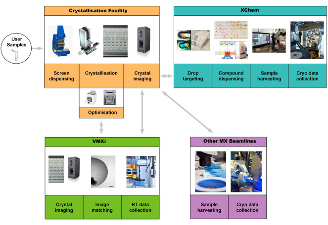
図1:結晶化スクリーニング、結晶化施設での最適化、VMXiでのサンプルハーベスティングを伴わない室温での自動データ収集と処理、XChemフラグメントスクリーニング、他のMXビームラインでのデータ収集を統合したタンパク質から構造へのパイプラインの概略図。 ユーザーは、サンプルを供給するか、プレートをVMXiビームラインに持ち込むことで、パイプラインを開始できます。略語:Versatile Macromolecular Crystallography in situ. この図の拡大版をご覧になるには、ここをクリックしてください。
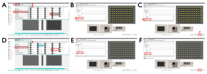
図2:結晶化プレートをセットアップするためのMosquito SPT Labtechインターフェース。 (A) (1) MiTeGen In Situ-1 セットアップ ビュー。(2)96ウェルプレートタイプに進み、(3)MiTeGenプレート2ドロッププレートを選択して、MiTeGen 2ドロップ標準プレートを選択します。VMXi に必要なドロップ 1 とドロップ 2 の定義パラメータを変更するには、(4) 編集アイコンをクリックします。これにより、新しいウィンドウ(B)が開き、(5)XとYのオフセットを図のように変更する必要があります。(B)サブウェル2と(C)サブウェル3を選択し、それに応じて値を変更します。(D)CrystalQuickX セットアップ ビュー。96ウェルプレートタイプに移動し、MiTeGenプレート2ドロッププレートを選択して、CrystalQuickX 2ドロップスタンダードプレートを選択します。VMXi に必要なドロップ 1 とドロップ 2 の定義パラメータを変更するには、上記と同じ編集アイコンをクリックします。これにより、新しいウィンドウが開き、(E,F)XとYのオフセットを図のように変更する必要があります。この図の拡大版をご覧になるには、ここをクリックしてください。
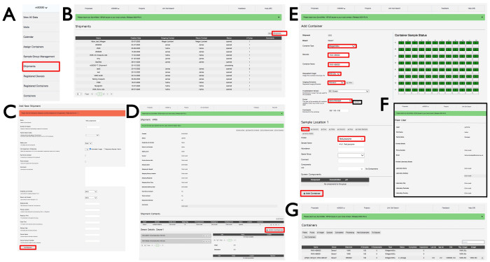
図3:VMXi出荷の作成方法、プレートの登録方法、連絡先の詳細の確認方法を示すSynchWebインターフェイス。 (A)ドロップダウンメニュー、(B,C)新規出荷の登録、(D)新規コンテナの登録、(E)プレート情報の入力、(F)連絡先の確認、(G)プロポーザル内の登録済みコンテナのリストから、SynchWebインターフェイスに情報をアップロードするさまざまな段階のスクリーンショットが表示されます。 この図の拡大版をご覧になるには、ここをクリックしてください。
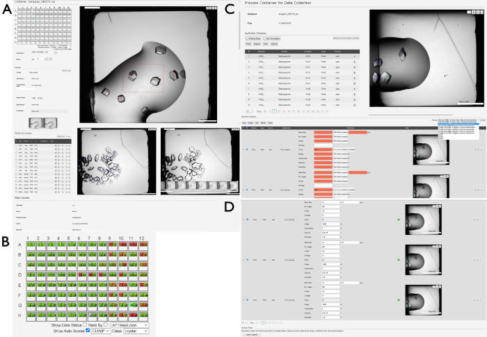
図4:SynchWebを使用したデータ収集用のサンプルの選択と準備。 SynchWeb インターフェイスを使用してデータ収集用のサンプルを準備するさまざまな段階を示す一連のスクリーンショットが表示されます。(A)関心のあるポイントと領域は、ドロップオーバービューから選択されます。このパネルの下部には、一滴の写真が年代順に並んでいます。(B)「結晶」カテゴリの結果を強調した1枚のプレートのCHiMP出力の例。(C)選択されたポイントと領域のリストからキューにサンプルを追加し、(D)ビームラインで作成した実験設定のドロップダウンリストからキューに入れたサンプルにデータ収集用のパラメータを適用します。実験パラメータのないサンプル(赤)と、パラメータが正しく適用されたサンプル(上と下)の違いに注目してください。このパネルの下部には、ビームラインで収集するプレートをキューに入れるための [キューコンテナ ]ボタンがあります。 この図の拡大版をご覧になるには、ここをクリックしてください。
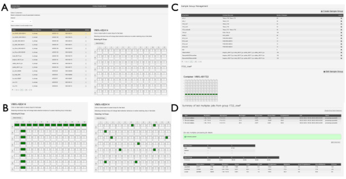
図5:SynchWebでのグループ作成例サンプルグループ作成のさまざまな段階を示す一連のスクリーンショット。(A)サンプルを含むプレートは関連する貨物から選択され、(B)プレート内のドロップが選択されます。これらは、個々のドロップである場合もあれば、行や列で選択することもできます。(C) 作成済みのサンプルグループの一覧。(D) 最後の 3 つの多重化処理ジョブの出力が一覧表示され、処理パイプラインからの統計を表示するように選択できます。この図の拡大版をご覧になるには、ここをクリックしてください。
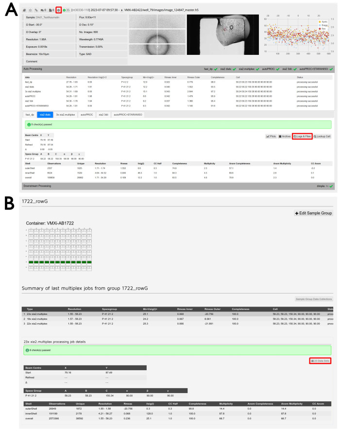
図6:データ処理とデータ削減。 (A) ISPyB11で処理されたデータセットのスクリーンショット。再処理機能にアクセスするためのボタンが強調表示されます。サンプルIDと実験パラメータは左上に、回折画像ビューアは中央に表示されます。この画像をクリックすると、インタラクティブなウィンドウが開き、さまざまな画像を調べることができます。右側に結晶画像ビューアが表示され、この画像をクリックすると、ビームラインとフォーミュラトリックスのストレージ画像を比較するためのインタラクティブなウィンドウが開きます。画像ごとの分析プロットが右端に表示され、この画像をクリックすると、この出力の拡大バージョンが開きます。[ 自動処理 ] タブをクリックすると、自動処理が表示され、異なるパイプラインの結果を簡単に比較できます。タブをクリックすると、さまざまな処理パイプラインが切り替わり、選択したパイプラインの詳細な出力が表示されます。データダウンロード用の 「Logs & Files 」ボタンが強調表示されます。[ Downstream Processing ] タブをクリックすると展開され、必要に応じてデータ削減後のパイプラインで実行されたデータセットの結果が表示されます。(B) サンプルグループ管理 画面のスクリーンショット。ユーザー定義のグループ名が上部にあり、含まれているウェルの視覚的な説明が下に表示されます。緑色のウェルは、その滴から測定されたすべての結晶がグループに含まれることを示します。そのグループで実行されたさまざまなマルチプレックスジョブの概要が表示され、その下にマルチプレックスからの詳細な出力が表示されます。含まれている実験を調べるための データセット ボタンが強調表示されます。 この図の拡大版をご覧になるには、ここをクリックしてください。

図7:データ再処理ウィンドウ。 (A)個別データセット、(B)多結晶データセット。データの領域が選択されている 2 つの個別のデータセットが表示されます。 Process individually チェックボックスにチェックを入れると、 Integrate ボタンを押すと、選択した回折像が個別に処理されます。 Multi-crystal ボタンをクリックすると、個々のデータセットが表示されます。複数のデータセットから回折画像を再解析するには、画像の領域を表示されているように選択し、ハイライトされているように[ 統合 ]ボタンをクリックして再処理を開始します。 この図の拡大版をご覧になるには、ここをクリックしてください。
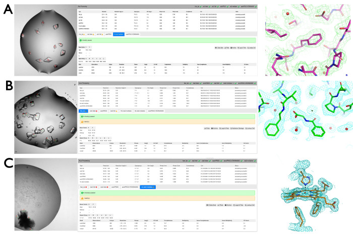
図8:VMXiパイプラインの代表的な結果。 (A)結晶化滴内のタンパク質ソーマチンのマークアップ結晶(左パネル)、データ処理結果(中央パネル)、電子密度(右パネル)。(B)SARS-CoV-2マクロドメインへのフラグメントの結合を決定するための複数の結晶の収集。データセットは、標準的な実験設定を使用して、EU-OPENSCREENフラグメントスクリーニングからフラグメントの存在下で複数の結晶に収集されました。これらのデータ収集の例は、SynchWebからの抜粋に示されています。破片は対応する密度に組み込まれ、右端に表示されているようにさらに洗練されています。(C)データ収集に使用した困難な結晶化ヒットからスタックされたマークアップされた単斜晶系結晶。緑の十字と赤の数字は、10 μmのビームと60°の回転を使用してデータが測定された場所を示しています。得られたウェッジのうち4つをマージして、1.75 Åの解像度でデータセットを生成しました。ヘム群周辺の電子密度が右に表示されます。 この図の拡大版をご覧になるには、ここをクリックしてください。

図9:結晶化プレート内の連続結晶構造解析。 (A)結晶化滴の光学画像で、白いボックスは関心領域を表します。(B)グリッドスキャンポイントの定義。(C)回折を示すヒートマップ。(D)9,000以上の静止回折パターンからの連続結晶構造解析データセットから得られた電子密度マップ。 この図の拡大版をご覧になるには、ここをクリックしてください。
| 解像度 (Å) | 完全性 (%) | 多様 性 | I/σ(I) | R分割 | CCの1/2 | ユニークな観測値 |
| 全 | 100 | 95.5 | 20.8 | 0.063 | 0.998 | 8422 |
| 安値 (55.55 - 5.43) | 100 | 147.1 | 81.7 | 0.028 | 0.999 | 488 |
| 高値 (2.03 -2.00) | 100 | 75.3 | 1.2 | 1.092 | 0.410 | 411 |
表 1: VMXi RT シリアル データセットのデータ統計。略語: I =スケーリングされた観測値の平均強度。Rスプリット =測定された強度の不一致の尺度。CC 1/2 = データセットの 2 つのランダムな半分間の相関係数。
ディスカッション
CFへのタンパク質サンプルの到着から、さらなるアプリケーションのためのユーザーによる最終データのダウンロードまでの全手順を説明しました。重要なステップは、市販のスパースマトリックススクリーニングまたは確立された条件に基づく最適化スクリーニングのいずれかを使用して、高品質のタンパク質サンプルと適切なクリスタルスクリーニングを製造することです。このプロセスはCFで行われる場合もあれば、ユーザーが自宅の研究室で結晶化手順を実行し、適切な結晶化プレートをビームラインに持ち込むこともできます。適切なデータ収集パラメータの特定は、特定のサンプル、特に放射線損傷が懸念される場合に重要な場合があります。ほとんどの場合、科学的な疑問に答えるには、自動データ処理で十分ですが、例えば、空間群が曖昧な場合や、放射線障害の影響を最小限に抑えるために収集されたデータの最初の部分のみを使用する場合など、ユーザーはビームラインツールを使用して再処理することができます。
最初の結晶化試験から適切な結晶が生成されない場合は、結晶播種の使用と同様に、タンパク質濃度、純度、または結晶化スクリーニングの変化を調べることができます。結晶がビームラインで有用な分解能に回折しない場合は、減衰していないビームでグリッドスキャンを使用して、結晶固有の回折限界と単位セルを評価し、最適化の取り組みを導くことができます。プレート内のデータ収集には小さすぎる結晶(例:<10 μm)は、代わりに連続結晶構造解析またはナノフォーカス実験(例:ダイヤモンドビームラインVMXm)に適している場合があります。VMXiデータを使用した構造の解析は、特に効果的な検索モデルを提供するAlphafold16 の出現以来、分子置換によって一般的に簡単になりました。これがうまくいかない場合は、従来の単一波長異常回折、多波長異常回折、または長波長位相実験を可能にするために、プレートから結晶を回収して凍結冷却することができます。
この方法の利点は、結晶が成長した環境から結晶を乱すことなく、結晶化プレートから直接迅速で高品質のデータセットとフィードバックを取得できることが含まれます。構造生物学におけるいわゆる「室温ルネッサンス」では、非極低温条件下で得られた構造を重視し、より生理学的関連性とタンパク質動態を探求できるようにしています2。通常、最適化されたクライオ冷却結晶よりもわずかに低い分解能が達成されるが、それは適切なクライオ条件が確立され、結晶が結晶化滴3の機械的取り扱いおよび開口に対して堅牢である場合に限られる。このパイプラインが非常に適している今後のアプリケーションは、創薬における室温でのタンパク質-リガンド複合体またはフラグメントキャンペーンの大規模なスクリーニングです。リガンドまたはフラグメントは、室温でのデータ収集の前に、ピペットまたはアコースティックドロップエジェクションによって共結晶化または添加することができます。また、数百または数千の結晶からのデータを非常に効率的な方法で迅速に測定し、DIALS17 マルチプレックス14 ソフトウェアを使用して、異なる生物学的実体を表す同形クラスターを抽出したり、異なる方法で処理されたり、異なるリガンドやシグナルに曝露されたりした結晶の集団間で統計的に有意な差を確立することも応用できます。
開示事項
著者は利益相反がないことを宣言します。
謝辞
VMXiビームラインの設計、建設、運用に貢献した多くのダイヤモンド光源の科学者とサポートチームメンバーに感謝します。ビームライン利用者の皆様には、結晶化・データ収集パイプラインの開発にアイデアを寄せていただき、感謝しています。ハーウェルの結晶化施設は、Diamond Light Source Ltd、Rosalind Franklin Institute、およびMedical Research Councilの支援を受けています。
資料
| Name | Company | Catalog Number | Comments |
| Formulator | Formulatrix | on request | Liquid handling robot |
| Formulatrix imager | Formulatrix | on request | Crystallisation plate imager |
| Greiner CrystalQuick X | Greiner | Z617644 | Crystallisation plate |
| Gryphon | Art Robbins Instruments | 620-1000-10 | Crystalisation robot |
| MiTeGen Insitu-1 | Mitegen | InSitu-01CL-40 | Crystallisation plate |
| Mosquito LCP | (SPT Labtech) | on request | Crystallisation robot |
| Rock Imager & Maker | Formualtrix | on request |
Software for Imager [1] https://formulatrix.com/protein-crystallization-systems/rock-maker-crystallization-software/ |
| Scorpion | Art Robbins Instruments | 640-1000-10 |
Liquid handling robot https://www.artrobbins.com/scorpion |
参考文献
- Lynch, M. L., Snell, M. E., Potter, S. A., Snell, E. H., Bowman, S. E. J. 20 years of crystal hits: Progress and promise in ultrahigh-throughput crystallization screening. Acta Crystallographica Section D Structural Biology. 79 (Pt 3), 198-205 (2023).
- Fischer, M. Macromolecular room temperature crystallography. Quarterly Reviews of Biophysics. 54, 1 (2021).
- Helliwell, J. R. What is the structural chemistry of the living organism at its temperature and pressure. Acta Crystallographica Section D Structural Biology. 76 (Pt 2), 87-93 (2020).
- Thorne, R. E. Determining biomolecular structures near room temperature using x-ray crystallography: Concepts, methods and future optimization. Acta Crystallographica Section D Structural Biology. 79 (Pt 1), 78-94 (2023).
- Keedy, D. A., et al. Crystal cryocooling distorts conformational heterogeneity in a model michaelis complex of dhfr. Structure. 22 (6), 899-910 (2014).
- Huang, C. Y., et al. Probing ligand binding of endothiapepsin by 'temperature-resolved' macromolecular crystallography. Acta Crystallographica Section D Structural Biology. 78 (Pt 8), 964-974 (2022).
- Sanchez-Weatherby, J., et al. Vmxi: A fully automated, fully remote, high-flux in situ macromolecular crystallography beamline. Journal of Synchrotron Radiation. 26 (Pt 1), 291-301 (2019).
- Jacquamet, L., et al. Automated analysis of vapor diffusion crystallization drops with an x-ray beam. Structure. 12 (7), 1219-1225 (2004).
- Mikolajek, H., et al. Protein-to-structure pipeline for ambient-temperature in situ crystallography at vmxi. IUCrJ. 10, 420-429 (2023).
- Douangamath, A., et al. Achieving efficient fragment screening at xchem facility at diamond light source. Journal of Visualised Experiments. (171), (2021).
- Delageniere, S., et al. Ispyb: An information management system for synchrotron macromolecular crystallography. Bioinformatics. 27 (22), 3186-3192 (2011).
- Fisher, S. J., Levik, K. E., Williams, M. A., Ashton, A. W., Mcauley, K. E. Synchweb: A modern interface for ispyb. Journal of Applied Crystallography. 48 (Pt 3), 927-932 (2015).
- Jenkins, J., Cook, M. Mosquito®: An accurate nanoliter dispensing technology. JALA: Journal of the Association for Laboratory Automation. 9 (4), 257-261 (2016).
- Gildea, R. J., et al. Xia2.Multiplex: A multi-crystal data-analysis pipeline. Acta Crystallographica Section D Structural Biology. 78 (Pt 6), 752-769 (2022).
- Winter, G., Mcauley, K. E. Automated data collection for macromolecular crystallography. Methods. 55 (1), 81-93 (2011).
- Jumper, J., et al. Highly accurate protein structure prediction with alphafold. Nature. 596 (7873), 583-589 (2021).
- Winter, G., et al. Dials as a toolkit. Protein Science. 31 (1), 232-250 (2022).
転載および許可
このJoVE論文のテキスト又は図を再利用するための許可を申請します
許可を申請さらに記事を探す
This article has been published
Video Coming Soon
JoVEについて
Copyright © 2023 MyJoVE Corporation. All rights reserved