2光子重合によるマイクロスケール神経細胞培養装置の3Dプリンティング
要約
マイクロメートルスケールの3Dプリンティングにより、神経細胞培養用のポリマーデバイスのラピッドプロトタイピングが可能になります。原理証明として、ニューロン間の構造的結合は、神経突起伸長に影響を与える障壁とチャネルを作成することによって制約され、そのような操作の機能的結果は細胞外電気生理学によって観察されました。
要約
ニューロン培養は、数十年にわたって参照実験モデルとなってきました。しかし、3D細胞配列、神経突起伸長の空間的制約、および現実的なシナプス接続性が欠落しています。後者は、区画化の文脈における構造と機能の研究を制限し、神経科学における文化の重要性を減少させます。シナプス結合の構造的な解剖学的配置を ex vivo で近似することは、リズム、シナプス可塑性、そして最終的には脳の病態生理学の出現の鍵であるにもかかわらず、自明ではありません。ここでは、3Dプリンティング技術として2光子重合(2PP)が採用されており、ポリジメチルシロキサン(PDMS)を用いた高分子細胞培養装置をマイクロメートルスケールで迅速に作製することができます。2PPマイクロスケール印刷は、マイクロフォトリソグラフィーに基づく従来のレプリカ成形技術と比較して、プロトタイプの迅速かつ手頃な価格のターンアラウンドを可能にします。このプロトコルは、モジュール式ニューロンネットワークの培養を目的としたPDMSベースのマイクロ流体デバイスの設計と製造を示しています。原理実証として、接続性を物理的に制限するための2チャンバーデバイスを提示します。具体的には、 ex vivo 発生中の非対称軸索伸長が好まれ、一方のチャンバーから他方のチャンバーに向けることができます。単方向シナプス相互作用の機能的影響を調べるために、相互接続されたニューロンモジュールの生体電気的活動を監視するために、市販の微小電極アレイが選択されています。ここでは、1)マイクロメートル精度で金型を作製する方法、および2)ラット皮質神経細胞培養における in vitro マルチサイト細胞外記録を行う方法が例示されている。コストを削減し、将来的に2PP 3Dプリンティングが広く普及することで、この手法は世界中の研究所でますます重要になっていくでしょう。特にニューロテクノロジーやハイスループットな神経データ記録では、 in vitro モデルのプロトタイピングの容易さと迅速さにより、 in vivo 大規模神経システムの実験制御と理論的理解が向上します。
概要
行動する生物の神経活動を調べるには、いくつかの課題があります。例えば、脳組織への物理的なアクセスは、その完全性を維持する必要性によって制限されるため、脳の表面領域はより簡単に考慮されます。無傷の組織内で特定のターゲットを単離することは、しばしば困難な作業であり、時には不可能です。解離した均質な神経細胞培養は、神経回路の個々の(サブ)細胞成分の分子的、生化学的、および生物物理学的特性への便利なアクセスを提供しますが、無傷の脳の現実的な接続性と解剖学的構成は失われます。これらの基本的な制約は、in vivoの複雑さを回避しながら、in vitroで構造を構築できるという中間点を達成するための研究努力を促しました1,2,3,4,5,6,7,8,9 .特に、モジュール式神経細胞培養は、以下に述べるような脳生理学の重要な問題に取り組むことを目的として、過去数十年にわたって広範な研究の対象となってきました。
組織:In vivoの研究によると、脳は解剖学的に正確な細胞タイプと突起の配列を持つ層に構造化されています。機能アッセイにより、ノードアセンブリとモジュール内のニューロンネットワークの組織化が、正確な接続スキームで明らかになりました10,11。しかし、コネクティビティとマイクロ回路モチーフの役割は、関与するシナプスの数が非常に多いこと、および発生と活動依存的な可塑性の織り交ぜられた効果のために、in vivoで十分に研究することはできません。
信号転送:in vivoまたは無作為in vitro培養では、シグナル伝達を評価することは困難です。軸索伝導とその長さに沿った活動電位を調べるには、表面機能化または化学的パターニングによって神経突起伸長を誘導する必要があり、電気的活動の細胞外読み出しにおいて高い信号対雑音比を提供する12。
翻訳の関連性: 病理学的状態におけるシナプス前部要素とシナプス後部要素の排他的な役割を解読するには、これらの要素に個別にアクセスする必要があります。シナプス前部とシナプス後部の要素を効果的に分離する、接続性が制限されたモジュール培養は、この目的に不可欠なツールです13。
神経細胞培養において何らかの構造を得るには、いくつかの方法があります。それらは、化学的および物理的な表面操作として大まかに分類できます9。前者の方法14,15は、神経細胞が特定の(生)化合物に付着する傾向に依存している。これには、接着剤や魅力的な分子をマイクロスケールの精度で、詳細なパターンに従って表面に堆積させる必要があります。これは、所望のパターンに従って、細胞の表面の部分的な被覆を可能にするが、化学的方法は本質的に制限されており、神経突起成長ガイダンスにおける比較的低い成功率を有する16。軸索の方向性を完全に制御するには、軸索誘導を形成するためのアドホック化学物質の空間的勾配を確立する必要があります17。後者の方法は、物理的な表面操作を含み、in vitroでニューロンネットワークを構築するためにより一般的に使用されます。神経細胞は、微細なチャンバー、壁、チャネルなどの幾何学的閉じ込めによって所望の位置に物理的に拘束され、ポリジメチルシロキサン(PDMS)3,5,6,7,18,19,20などの生体適合性ポリマーを成形し、硬化・固化させてマイクロ流体デバイスを形成します。PDMSマイクロ流体製造の事実上の方法は、2次元マスクをマイクロスケールでパターニングし、UV露光時にシリコンベースの材料を選択的にエッチングするために採用されるソフトフォトリソグラフィー21である。簡単に言うと、UV硬化樹脂(フォトレジスト)をスピンコートしてシリコンウェーハ上に塗布し、その粘度と回転速度によって決まる特定の高さに到達します。次に、パターン化されたマスクをフォトレジスト上に配置し、UV光に露光します。マスク内の透明な領域は、関心のある領域に対応し、UV光がフォトレジスト分子の局所的な架橋を誘導できるようにします。露光されていないフォトレジストの領域を溶剤で洗い流し、マスターモールドを形成します。これを繰り返し使用して、選択したエラストマー(PDMS)を焼成し、必要な数のレプリカに目的の形状を彫刻します。このような製造方法は、マイクロ流体デバイス22を製造するための最も一般的な方法である。おそらく、ソフトフォトリソグラフィーの主な限界は、注目すべき設備投資の前提条件と、必要な技術と専門知識を備えた生物学研究室の不慣れです。複雑な複数の高さの高アスペクト比の形状を設計するために必要なマスクの準備とソフトフォトリソグラフィーのステップは、自明ではなく23、しばしばアウトソーシングを必要とします。代替の低予算の方法が提案されているが、それらは必ずしも生物学的プロトタイピングの高精度要件を満たしているわけではない24。
ここでは、2光子重合(2PP)と積層造形に頼った代替製造方法を紹介します。これは簡単で、高度な微細加工やマイクロフォトリソグラフィーの専門知識を必要としません。2PPマイクロマニュファクチャリングの研究分野は90年代後半に登場し25、それ以来、指数関数的な成長を遂げてきました26。この手法の基本原則の詳細については、他の場所 26 を参照してください。簡単に言うと、励起光インパルスを3次元空間に集束させることで、2PPは多光子吸収の強度に対する非線形依存性を利用します。これにより、限られた吸収が可能になり、非常に局所的な領域内で正確かつ選択的な励起が保証されます。要するに、光露光時に溶解度が低下する材料であるネガトーンフォトレジストは、低デューティサイクル27でフェムト秒レーザーパルスの集束ビームを受ける。これにより、低い平均出力で高強度のインパルスが可能になり、材料を傷つけることなく重合が可能になります。光誘起ラジカルモノマーの相互作用は、ラジカルオリゴマーを生じさせ、そのサイズがレーザーパルスの強度および持続時間に依存する明確な体積、すなわちボクセルまでフォトレジスト全体に広がる重合を開始する28。
本研究では、A)使い捨ての高分子神経細胞培養デバイスを製造するために何度も再利用できる3Dプリント金型の設計と迅速な製造(図1)、およびB)平面神経細胞培養基板の表面、または生体電気信号のマルチサイト記録が可能な基板一体型微小電極アレイへの機械的結合の2つのコンポーネントが提示されています。
ここでは、3D機械モデルのコンピューター支援設計について非常に簡単に説明し、3Dプリントされた金型とPDMSデバイスの製造につながる手順についても詳しく説明します。
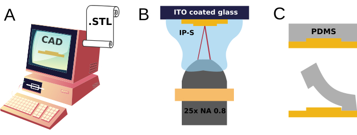
さまざまなコンピューター支援設計ソフトウェアアプリケーションを使用して、開始3Dオブジェクトモデルを生成し、2PP印刷プロセスを制御するSTLファイルを生成できます。 材料表では、最初と最後のアプリケーションが無料または無料ライセンスで提供されています。3D モデルを構築するには、常に 2D スケッチを作成する必要があり、その後のモデリング手順で押し出されます。この概念を示すために、一般的な3D CADソフトウェアの設計プロセスがプロトコルセクションで強調表示され、重なり合う立方体で構成された構造が導かれます。より包括的な情報については、 材料表に示されているように、多数のオンラインチュートリアルと無料のトレーニングリソースが利用可能です。
結果のSTLファイルは、3Dプリンターによって実行される一連のコマンド(つまり、スライス手順)に変換されます。使用している特定の2PP 3Dプリンターでは、ソフトウェアDeScribeを使用してSTLファイルをインポートし、独自のGeneral Writing Language(GWL)形式に変換します。2PP印刷プロセスの成功は、レーザー出力とそのスキャン速度、ステッチング、ハッチングスライス距離など、さまざまなパラメータにかかっています。これらのパラメータの選択は、対物レンズとフォトレジストの選択とともに、設計の最小機能と意図されたアプリケーションによって異なります。したがって、さまざまな設計シナリオやユースケースの要件を満たすために、パラメータの最適化が不可欠になります。この作業では、印刷パラメータの構成として、推奨レシピIP-S 25x ITO Shell(3D MF)を検討しました。最終的に、機械的に安定したプリント部品は、3Dプリント時間を最小限に抑えながら、必要な解像度でプリントされます。
本研究で実証された金型設計および関連するSTLファイルは、細胞培養の空間を2つのコンパートメントに分離するための正方形のフレームで構成されています:外側の領域(つまり、その後、ソースと呼ぶ)と内側の領域(つまり、ターゲットと呼ぶ)。これらの2つの区画は、それぞれが鋭角の境界を特徴とするマイクロチャネルのセットを介して接続されており、ターゲットからソースへの神経突起の成長を特に妨げるように設計されていますが、その逆はないため、2つの領域で成長するニューロン間の方向性のあるシナプス接続を促進します。
初期の研究では、神経突起の方向性のある成長を促進するために、マイクロチャネルのさまざまな形状が採用されていました。例としては、三角形形状18、チャネル有刺鉄線構造19、およびテーパーチャネル20が含まれる。ここでは、マイクロチャネルの境界を横切る鋭角の障壁を特徴とするデザインが採用されており、非対称の入り口も特徴です。これらのマイクロチャネルは、密閉された内部(ターゲット・コンパートメント)と外部領域(ソース・コンパートメント)の間の連続性を確立する役割を果たします。マイクロチャネルの最初の部分の漏斗形状は、ソース側から見て、ソースとターゲットを結ぶ最短の経路、すなわち直線に沿った軸索束の形成とその成長を促進するように設計されています。鋭角を向いて実現される三角形の空間は、ターゲット側の体積が大きくなり、神経突起の経路探索を効果的に遅らせることを狙いとし、ソースから発生する束の迅速な発射と利用可能な空間の占有を有利に進めます。マイクロチャネルの長さに対する540μmの選択は、一般的に短い樹枝状突起伸長を効果的に濾過する39。さらに、高さが5μmであるため、細胞体細胞がマイクロチャネルを貫通するのを防ぎます。全体として、この構成は、外部(ソース)モジュールと内部(ターゲット)モジュール間の単方向接続を促進することが証明されており、ここでは、多くの代替選択肢の原理実証として提示します。
2PPモールドで作製されたPDMSデバイスは、ガラスカバーガラスやペトリ皿などの一般的な細胞培養基板の表面に取り付けることができますが、この研究では、市販の基板一体型微小電極アレイを使用しました。3D設計を微小電極アレイのレイアウトに最適化する努力は行われておらず、機械的結合は、アレイ全体にデバイスを配置することのみを目的とした実体顕微鏡ガイダンスの下で行われ、ソースとターゲットの両側にいくつかの微小電極が露出したままになりました。これにより、神経細胞培養における接続性の制限による機能的影響の予備的評価が可能になります。
プロトコル
動物の取り扱いに関するすべての手続きは、欧州およびイタリアの法律(2010年9月22日の欧州議会および理事会指令[2010/63/EU];2014年3月4日イタリア政府令第26号)は、Scuola Internazionale Superiore di Studi Avanzatiの機関OpBA(Committee for Animal Care)によって明示的に承認され、イタリア保健省によって正式に承認されました(Auth. No. 22DAB.N.UVD)です。これにより、摘出されたラットの脳組織から非感覚物質が入手でき、この研究で提示された方法の実験的検証に使用できるようになりました。
二光子重合法による1. 3D型作製
- CAD ファイルの生成
注: 次の手順は、コンピュータ支援設計ソフトウェア(SolidWorks など)を使用した一般的な 3D 設計ワークフローを示しています。この作業で説明したサンプルSTL設計ファイル(図2)は、 Supplementary Coding File 1として、およびZenodo(https://doi.org/10.5281/zenodo.8222110)から入手できます。- コンピュータ支援設計ソフトウェアのデスクトップアプリケーションを起動します。上部のメニュー バーから、 新規 を選択します。
- オプションから、 パーツ: 1 つの設計コンポーネントの 3D 表現を選択します。 [Ctrl]+[5 ]のキーを押して、スケッチの上面図を作成します。
- サイド パネルから [スケッチ ]を選択し、[ コーナー矩形]を選択します。長方形の 1 つのエッジをクリックして選択します。パラメータパネルが表示されたら、長さを100単位に設定します。
- 前のエッジに垂直なエッジに対して手順1.1.3を繰り返します:その長さを50単位に設定します。矩形をマウスの左ボタンを押しながらドラッグして選択します。
- 「リレーションの追加」メニューから「固定」を選択し、ライン間のリレーションを制約します。
- スケッチを終了し、手順 1.1.3 から 1.1.5 を繰り返して、前のスケッチと重なる新しい(小さい)長方形を作成します。
- サイドパネルから Featuresを選択し、 Extruded Boss/Baseを選択します:大きい矩形と小さい矩形の両方の深さをそれぞれ5単位と10単位に設定します。
- [ファイル]メニューから、パーツを STL 形式(標準テッセレーション言語)で保存します。
- CAD ファイルの処理
- STLファイルをDeScribeアプリケーションソフトウェアを搭載したパソコンに転送します。
- Describeを起動し、[ファイル]メニューからSTLファイルを開きます。モデルの 3D 表現が表示されます。
- 右側のメニューの方向セクションで、モデルを回転させて空間内で適切な方向に配置し、平面の中央に配置します。
- 右側のメニューの [スケーリング ] セクションを選択して、全体的なスケーリングを調整します。
- 上部のドロップダウンメニューから、 IP-S 25x ITO Shell (3D MF) レシピを選択します。これにより、フォトレジストとしてIP-S、対物レンズの倍率を25倍、印刷基材として酸化インジウムスズ(ITO)コーティング基板、中型機能(MF)を備えた動作モードとしてシェルと足場印刷が指定されています。
- ウィザード内をナビゲートし、シェルとスキャフォールドの両方で [スライス距離 ] を 1 μm に、[ ハッチング距離 ] を 0.5 μm に設定して設定します。
- インポートウィザードの出力ステップの分割で、ブロックサイズをX = 200 μm、Y = 200 μm、Z = 265 μm、ブロックオフセットをX = 133 μm、Y = 133 μm、Z = 0として定義し、マイクロチャネルの繊細な構造がスティッチングラインの影響を受けないようにします。
- スキャンモードとして、デフォルトのX-Y平面にはガルボ、Z軸にはピエゾを使用します。
- [保存]を押し、次のテキストメニューで、var $baseLaserPower = $shellLaserPower行をvar $baseLaserPower = 75に置き換えて、印刷の最下層のレーザー出力を75%に減らします。
- 上記の手順で取得したGWLファイルを、2PP 3Dプリント専用のワークステーションに転送します。
- 3Dプリンティングとサンプル開発
- NanoWriteアプリケーションソフトウェアを起動します。プリンターの初期化後、ソフトウェアインターフェースの[ホルダーの交換]をクリックして、基板ホルダーを挿入し、対物レンズを取り付けます。
- 25倍対物レンズをノーズピースの適切な位置に取り付けます。抵抗を測定するように設定された電子マルチメータによって、ガラス基板のどちらの面がITOでコーティングされているかを特定します:読み取り値は100〜300 Ωなどの低い値である必要がありますが、ITOコーティングされた側のみです。
- ガラス基板をホルダーに置き、ITOコーティング面を上向きにします。テープを使用してしっかりと固定します。
- 化学ヒュームフードの下で、ガラス基板の中央にIP-Sフォトレジストを一滴塗布します。
- ホルダーを3Dプリンターに挿入し、レジンドロップを対物レンズに向けます(つまり、下向き)。
- ソフトウェアの 「ファイル」 メニューから、GWL ファイルをロードします。 Approach Sample(サンプルにアプローチ)を選択し、対物レンズをレジンドロップに近づけます。
- [ インターフェイスの検索 ]を選択すると、2つの材料の屈折率の差に基づいて、ITO-フォトレジスト印刷インターフェイスを検出できます。
- [ ジョブの開始 ]を選択して、印刷を開始します。印刷が終了したら、[ ホルダー交換] を押してホルダーを取り出します。
- ホルダーを取り出し、プリントされたパーツで基板をそっと取り外します。ガラス基板をプロピレングリコールメチルエーテルアセテート(PGMEA)にドラフト下で20分間浸し、プリント部品を現像します。
- PGMEAから基質を取り出し、イソプロパノールに5分間浸します。プリントした部品を化学ヒュームフードの下で風乾させます。
- 印刷後処理と金型実装
- UV光(365〜405 nm)に5〜20分間十分な電力で曝露して、プリント部品を硬化させます(電力の詳細については 、ディスカッション を参照してください)。
- 層流フードの下で、印刷部品をガラス基板からそっと取り外します。~2 μLのレジンを35 mm x 10 mmのシャーレの底に落とします。
- プリントしたパーツをドロップの上に慎重に置き、レジンをパーツの下に流します。さらに、UV光を5分間当ててプリントした部品を硬化させます。
- ペトリ皿をキャップで覆い、オーブンに移して80°Cで30分以上加熱硬化させます。 プリントパーツの変形や破損を防ぐために、オーブンを予熱しないでください。硬化後、プリントされた部品はペトリ皿の底に恒久的に取り付けられます。今後、印刷および実装された部品は金型と呼ばれます。
2. 金型と細胞培養基板からのPDMSデバイスの作製
- PDMSデバイス製造
- 未重合PDMSの塩基と硬化剤 の10:1(重量比)の混合物20 mLを調製します。各デバイスについて、必要な高さに応じて、1〜2 mLのPDMS混合物で十分です。余分な未重合PDMSは、後で使用するために-20°Cで保管してください。
- 層流フードの下で、混合物を4分間完全に攪拌します。混合物が気泡を均一に閉じ込めると、不透明になります。
- 混合物を50μLのμtubeに移し、168 x g で5分間遠心分離して、混合物から気泡を除去し、透明な外観を実現します。
- 金型を10 μLの疎水化剤(すなわち、反発シランES)で処理し、7分間休ませて、後で重合したPDMSが金型からスムーズに剥がれるようにします。
- 型を70%エタノールで1回、脱イオン(DI)水で2回すすぎます。層流フードの下で金型を風乾させます。
- PDMS混合物を金型に静かに流し込み、装置の最終高さに達するまで加熱します。気泡の発生を防ぐために、金型の表面に近距離から混合物を静かに注ぎます。
- 金型に蓋をし、80°Cで予熱して安定させたオーブンに18分間移し、硬化させます。装置の高さが5mm以上1cm以下の場合は、硬化時間を18分から25分に延長します。
- 層流フードの下で、硬化したPDMSブロックを金型から静かに取り外し、ガラスペトリ皿内のイソプロパノールに少なくとも10分間浸します。イソプロパノールは、未架橋のPDMSを排除します。PDMSブロックは常に覆ったままにしてください。
- イソプロパノールを刷新し、実体顕微鏡下で、眼科用刺しナイフで装置の中央の四角い部分(この作業ではターゲット領域として識別)を慎重に切り取ります。次に、エッジに沿ってさらにカットして、デバイスの究極の形状を実現します。
- イソプロパノールからデバイスを回収し、エタノールに30分間浸した後、滅菌脱イオン水で3回すすいでください。この時点から無菌状態を維持します。
- 層流フードの下で、キャップを少し開いたままにして、デバイスを新しいペトリ皿に移します。完全に風乾させます。
- デバイスの取り付けと細胞培養基板の準備。
- 各微小電極アレイ(MEA)を70%エタノールに30分間浸漬して滅菌し、滅菌脱イオン水で3回すすいでください。
- 滅菌済みの細いピンセットを使用して、層流フードと実体顕微鏡の下で、PDMSデバイスをMEAの内部領域に取り付けます。PDMSデバイスの片側を、基板に集積された微小電極を特徴とするMEA領域の内側の中央に合わせ、ソース領域とターゲット領域の両方から露出した微小電極がほとんど残らないようにします( 図2を参照)。
注:この作業では、MEA微小電極をPDMSデバイスのマイクロチャネルに位置合わせする必要はありません。PDMSデバイスとMEA表面の間の密閉性を実現するには、デバイスを軽く押す必要がある場合があります。ピンセットの先端で微小電極に触れないでください。 - PDMSデバイスを搭載したMEAをプラズマクリーナーチャンバーに挿入し、エアプラズマによる表面活性化を活性化します。チャンバーを真空ポンプで4分間排気するプロセスを開始します。次に、エアバルブを少し開いて、エア抜きを制御できるようにします。エアバルブを閉じ、プラズマインデューサーのスイッチを入れて、RF電力レベルを10Wから18Wの間で調整します。
- 光るライトが表示されたら、プロセスを80秒間実行します。次に、プラズマインデューサーのスイッチを切り、真空ポンプバルブを閉じ、エアバルブを静かに開きます。チャンバーを開けてMEAを取り出します。
注:プラズマ処理でMEAを非滅菌環境にさらす場合は、各MEAを層流フード内のUV光下に30分間置き、無菌性を確保します。 - 1 mLのポリエチレンイミン(PEI)0.1%wt/vol溶液をMEAに加え、37°Cで一晩インキュベートします。PEI溶液を吸引し、滅菌脱イオン水で5回すすいでください。MEAに1 mLの細胞培養培地を加え、細胞播種前にインキュベートします。
3. 神経細胞培養と電気生理学
- 解剖培地、消化液、溶液1〜3を予め準備する( 表1参照)。
- 解離した神経細胞培養。
- 生後0〜1日の新生児ウィスターラットの子犬の鼻をそっとつかみ、鋭利なハサミを使用して迅速な斬首を行います。
- 頭皮の皮膚をはがし、細いハサミを使用して頭蓋骨の矢状正中線に沿って切開し、小脳の接合部で頭蓋骨に冠状の切り込みを入れます。
- 頭蓋骨を取り出し、細かいヘラで脳をすくい取り、冷たい(4°C)解剖培地に移します。
- 皮質下組織、海馬、髄膜を取り除きます。組織を小片(すなわち、1〜2 mm3)に細かく刻み、15 mLチューブに移します。溶液を廃棄し、新鮮な解剖培地を使用して組織をすすぎ、続いて消化培地で洗浄します。
- 消化培地を廃棄し、溶液1 mLを添加します。混合物を37°Cで5分間インキュベートします。溶液1を廃棄し、新鮮な解剖培地で組織をすすぎます。次に、1 mLの溶液2を加え、混合物を4°Cで10分間保持します。
- 溶液2を廃棄し、新鮮な解剖培地を使用して組織をすすぎます。次に、1 mLの溶液3を加えます。溶液を20〜30回ゆっくりとピペッティングして、細胞を機械的に解離します。解離した細胞の均一に濁った混合物が現れたら、解剖培地を添加してその容量を3 mLに上げます。
- 混合物を100 x g で5分間遠心分離して細胞ペレットを回収します。上清を吸引し、細胞ペレットを予熱した培地1mLに再懸濁します。
- 細胞を計数し(すなわち、細胞計数チャンバーによって)、それに応じて細胞播種溶液の密度を調整します。
- 各MEAに、公称細胞密度が1.8 x 10⁶ (~6500細胞/mm2)の1 mLの播種溶液を播種します。播種したMEAを湿度の高いインキュベーターで37°C、5%CO2でインキュベートします。培地は、2日ごとに新鮮な(つまり、毎週製造された)培地と交換します。
- 細胞外電気生理学
注:解離したニューロン細胞培養物は、 in vitroで2〜3週間後に完全に成熟した電気表現型に達します。以下のセクションでは、市販のMEAアプリケーションソフトウェア(実験装置)を使用して、モジュール(ソースまたはターゲット)で培養されたニューロン集団のいずれかを電気的に刺激し、成熟したネットワークで両方の集団の活性を同時に記録する細胞外刺激プロトコルについて説明します。- 1つのMEAをマルチチャンネル電子アンプのヘッドステージ内、ドライインキュベーター(37°C、5%CO2)内に静かに取り付け、10分間収容します。カスタムPDMSキャップを個別に製造し、各MEAのタイトカバーとして使用することで、水分の蒸発を減らし、無菌性を維持することができます。
- 実験ツールソフトウェアを起動します。サンプリングレートを25 kHzに設定し、[ DAQの開始]を押してデータ集録を開始します。データ表示パネルには、各チャンネルの細胞外活動の生のトレースが表示されます。
- 自発的な活動を監視し、ソース側またはターゲット側の微小電極から、ネットワーク全体の自発的同期された活動バーストのバースト中にアクティブな隣接する微小電極の3組を視覚的に識別して選択します。
- ソフトウェアの刺激パネルで、バイポーラ構成の各刺激微小電極ペアのパラメータを設定します:二相性パルス波形を選択し、ピーク振幅を±800mVに、パルス幅を200μsに設定します。
- レコーダーをセットし、刺激前300msから1000ms後まで記録します。
- 手順 3.3.3 から 3.3.5 を、ソース側とターゲット側に対して、必要な繰り返し回数だけインターリーブ方式で繰り返します。
代表的な結果
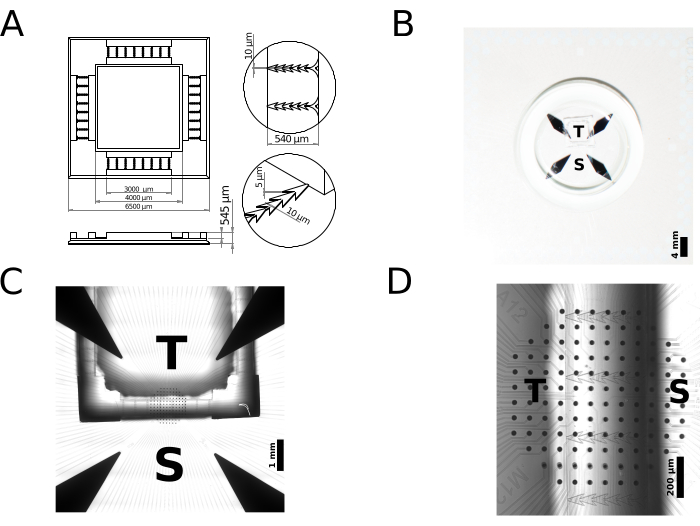
ここでは、PDMSデバイスのラピッドプロトタイピングのための2PP 3Dプリンティングの使用を例示する、2コンパートメントポリマー(ニューロン)細胞培養デバイスの製造について報告します。具体的には、単方向シナプス結合を有するモジュール式ニューロンネットワーク用のデバイスを作製し、その機能的特徴をマルチサイト細胞外電気生理学の観点から提示する。簡単に言うと、市販の3Dプリンターを使用して、直接レーザー描画によってマイクロメートルスケールの金型を実現しました。特に、中心波長780nm、持続時間80〜100fsのレーザーパルスで50mWの電力を供給します。製造プロセスでは、レーザービームがプリンターの対物レンズ(25倍、NA = 0.8)を介してネガトーンフォトレジスト(IP-S)に集束され、x軸とy軸にガルバノスキャナー、z軸にピエゾステージを使用して印刷ボリュームをスキャンします。印刷量を200mm×200mm×265mmのブロックに適切に分割し、全体のサイズ6500mm×6500mm×545mm、呼び体積12.423mLの金型を実現しました。 図2A は金型の2Dスケッチで、その寸法と特徴のサイズを強調し、 図2B はMEAに取り付けられた完成品のクローズアップ写真を示しています。前のセクションで説明したように準備された金型は耐久性があり、PDMSデバイスの製造に50回以上再利用できます。
印刷された金型は、PDMSデバイスの鋳造に使用され、その後、微小電極アレイ(MEA)のガラス基板集積アレイの内部領域に取り付けられ、神経細胞の電気的活動のマルチサイト細胞外記録および原理証明として使用されました。市販の基質統合MEAを使用して、各培養区画にある微小電気のサブセットによって細胞外に送達される空間的に局在した電気刺激に応答するモジュール培養の活性をモニターしました。各MEAには、直径30μm、電極間ピッチ100μmの硝酸チタン(TiN)微小電極が120個含まれています。図2C-Dは、MEAの上部にPDMSデバイスを配置した状態を示しています。図2Cに示すチャンバーの全体的な設置面積とともに、デバイスの個々のマイクロチャネルの幾何学的特徴は、培養ニューロンの区画化につながります。これらは、属するコンパートメント、デバイスの外側の領域(ソース)、またはデバイスの内側の領域(ターゲット)に基づいて区別できます。ソースからターゲットに制限された好ましい軸索ガイダンスは、マイクロチャネルの鋭角エッジによって決定されます。図2Dは、MEA上のポリマーデバイスの配置と、ソースまたはターゲットコンパートメント内に位置する記録電極の相対的なカバレッジ領域を示しています。なお、デバイスのマイクロチャネル内を1列以上のMEA微小電極に正確に位置合わせすることは、このケーススタディでは必要でも追求でもありませんでした。
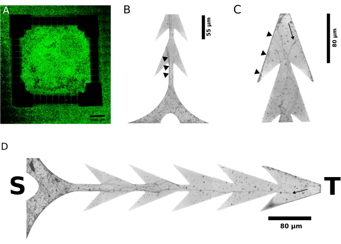
非対称神経突起成長の代表的な証拠は、細胞播種後6日(図3A)および2日後(図3B-D)のライブイメージングで蛍光タグ付き神経突起を示す、ex vivo発生中の図3に示されています。装置のターゲット側の神経突起は、空間の進行を妨げる障害物として鋭角の障壁に遭遇しましたが、ソース側から発生した神経突起は途切れることなく成長し、チャネルを横切りました。この非対称性は、設計から明示的に意図されているように、ソースからターゲットに投影される、2つのコンパートメント内のニューロン間の単方向軸索接続を支持します。この結果は、2つのコンパートメントのそれぞれに交互に送達される刺激によって誘発される電気的応答の(機能的)電気生理学的評価によってさらに裏付けられています。
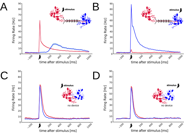
in vitroで3〜4週間後、ニューロンネットワークが完全に成熟すると29,30、2つのコンパートメント間の機能的接続性は、短時間の電気刺激を伝達し、それらが誘発するニューロン応答を監視することで調べることができました31。次に、振幅800mVの二相性電気インパルスを、ソース集団のみまたはターゲット集団(N回繰り返し=150回、Nモジュラー培養=6回)にのみ交互に印加し、バイポーラ構成の3組の平面微小電極を並置し、インターリーブ方式で送達しました。したがって、3対の電極は、MEAのソース領域内またはMEAのターゲット領域内に配置できます。各刺激によって引き起こされる電気的応答は、伝搬遅延後にすべてのMEA微小電極によって検出されます。録音は25kHz/チャンネルのサンプリングレートで行い、得られた細胞外の生の電気信号は、16ビットのアナログ-デジタル変換分解能でデジタル化されました。閾値交差ピーク検出アルゴリズム32をオフラインで使用して、スパイクソーティングを行わずに細胞外活動電位の発生時間を検出した。図4A-Bは、刺激の伝達場所に応じて150回繰り返される誘発応答の強い非対称性を明確に示しており、接続性の好ましい方向性に対する幾何学的制約の有意な機能的影響を示唆しています。実際、ソース側を刺激すると、ソースニューロン集団の発火率(刺激周囲のスパイク時間ヒストグラムを計算することによって推定される)は、予想どおりに増加し、活動電位のフルネットワークバーストを生成し33,31,34、遅延後、ターゲット集団の発火率の増加が続いた。しかし、刺激がターゲット集団内で行われたため、ターゲット集団の発火率のみが上昇し、ソース集団はほとんど沈黙したままでした。図4C-Dは、高分子デバイス(すなわち、非構造化ニューロン培養)を存在させない対照培養において、同じ刺激/応答パラダイムを繰り返し、細胞外刺激も4回繰り返して送達した。このような制御条件では、いずれの刺激によって誘発される応答にも非対称性は生じなかった。刺激を送達するために使用されるMEA微小電極のサブセットは、モジュラーネットワークで使用されるものと一致しましたが、刺激送達の位置は、集団全体から同様の誘発反応をもたらしました。これは、PDMSデバイスが2つの区画を横断する単方向シナプス結合を好んだことを裏付ける。全体として、モジュラー培養(N = 6)で誘発された非対称応答および対照培養(N = 4)で誘発された対称応答は、区画化されたin vitroシステムの制約された解剖学的接続性を強く示しています。図4の生成に使用された電気生理学的データとスクリプトは、Zenodo(https://doi.org/10.5281/zenodo.8220990)から入手できます。

図1:2PPマイクロモールド製造とPDMSレプリカ成形のスケッチ。(A) 3DモデルをCADで設計し、標準テッセレーション言語(STL)形式のファイルでエクスポートし、 (B) 樹脂の滴内でレーザー誘起重合(IP-S)を行うことで2光子3Dプリントを指示します。 (C) 得られた構造は、PDMSレプリカを繰り返し作製するための金型として使用されます。 この図の拡大版をご覧になるには、ここをクリックしてください。

図2:高分子(神経細胞)細胞培養PDMSデバイスの社内ラピッドプロトタイピングの例。(A) マイクロスケールのアディティブ・マニュファクチャリングでは、24時間以内にCADモデルから3Dプリントされたマスターに移行し、PDMSなどの生体適合性エラストマーを使用したレプリカ金型として、即座に繰り返し使用できます。 (B-C) 得られたPDMSデバイスは、ニューロン細胞培養平面基板(ここでは微小電極のアレイで表される)に結合される。 (A)の特定のサンプルデザインでは、2つのチャンバーが定義 されています:1 つはソースと呼ばれ、Sで示され、もう1つはターゲットと呼ばれ、Tで示されます。 各チャンバーに播種されたニューロンは、一連のマイクロチャネルを介してのみ神経突起を成長させることができます。 (C)の実体顕微鏡ガイド下で適切に位置合わせすると、2組の基板に統合された微小電極が露出したままになり、両方の区画に位置する近くのニューロンの生体電気的活動が刺激され、記録されます。ここで、個々のマイクロチャネル内での微小電極のアライメントは、この原理実証の優先事項ではなかったことに注意してください。 この図の拡大版をご覧になるには、ここをクリックしてください。

図3:細胞不透過性蛍光レポーター分子のライブイメージングにより、細胞プレーティングの数日後にニューロンによって伸長した神経突起が同定されました。(A-D)図1および図2から作製したデバイスのモジュール式ニューロン培養の代表的な共焦点蛍光顕微鏡写真(N = 4、128個のマイクロチャンネル)は、細胞プレーティングの2日後および6日後に取得されました。(B-D)視認性を高めるための顕微鏡写真の40倍の倍率と反転グレースケール。ソース・コンパートメントとターゲット・コンパートメントからのマイクロチャネルの末尾は、それぞれSとTで表されます。(A)は、プレーティング後6日後の培養物のワイドスキャン画像を示しており、ソース(すなわち、内側の正方形の領域)とターゲット(すなわち、外側の領域)が細胞でいっぱいです。(B)および(C)は、めっき後2日という早い時点において、それぞれマイクロチャネルのソース側とターゲット側での神経突起の成長を示しています。小さな黒い三角形は、推定軸索束末端の代表例を示しており、明らかにソースからのみ発生しています。矢印の形をしたマイクロチャネルの境界は、エッジ(B)に沿った神経突起の伸長を指しており、その通過は途切れることなくターゲットに向かって導かれます。反対方向では、マイクロチャネル(C)のターゲット末端の隣で、ターゲットから発生し、ソース側に進む神経突起が鋭い角に閉じ込められます。(D)は、マイクロチャネル内の神経突起伸長の詳細をさらに明らかにする。この図の拡大版をご覧になるには、ここをクリックしてください。

図4:PDMSデバイスを使用する場合と使用しない場合のニューロンの電気応答の機能的特性評価。 MEAを細胞培養基質として使用し、バイポーラ構成で送達された非常に短い(すなわち、200μs、0.8V)二相性電気刺激パルスによって誘発されるネットワーク全体のスパイク応答を測定するために使用しました。 図2のPDMSデバイスでは、ソース(赤)とターゲット(青)から記録されたニューロンのスパイク応答は、刺激が送達される場所によって異なります。推定される軸索、シナプス、および統合の遅延は、 (A) では明らかになるが、 (B)では明らかになり、好ましいシナプス接続(すなわち、ソースからターゲット)が存在することを示唆している。 (C-D) 制御条件下(すなわち、PDMSデバイスなし)では、2組の異なるMEA微小電極で検出された誘発応答は、刺激送達位置に依存しない。プロットの線を包む淡い色合いの陰影は、平均の瞬間的な標準誤差(N刺激 = 150)を示します。 この図の拡大版をご覧になるには、ここをクリックしてください。
| ソリューション名 | 組成 | ||
| ポリエチレンイミン(PEI)0.1% | 1 mL の PEI ストック溶液、9 mL の滅菌脱イオン(DI)水。 | ||
| 培地(50 mL) | 最小必須培地(MEM)に、20 μM グルコース、50 μg/mL ゲンタマイシン、50 μM L-グルタミン、および 10% 熱不活化馬血清を添加します。 | ||
| 解剖培地(1000 mL) | ハンクスバランス塩9.52 g、重炭酸ナトリウム350 mg、HEPES 2.83 g、D-(+)-グルコース6 g、キヌレン酸(最終濃度200 μM)、D-AP5(最終濃度25 μM)、ゲンタマイシン250 μl、ウシ血清アルブミン300 mg、硫酸マグネシウム1.44 g。pHを7.3に調整し、光から保護し、4°Cで保管してください。 | ||
| 消化培地(100 mL) | 塩化ナトリウム800mg、塩化カリウム37mg、リン酸水素二ナトリウム99mg、HEPES 600mg、炭酸水素ナトリウム35mg、キヌレン酸、200μL(100mMストックから)、D-AP5 100μL(ストック25 mMから)。pHを7.4に調整し、光から保護し、4°Cで保管します。 | ||
| ソリューション 1 | トリプシン 5 mg、デオキシリボヌクレアーゼ I 1.5 mg、消化培地 2 mL 中。 | ||
| ソリューション 2 | トリプシン阻害剤 5 mg、5 mL の解剖培地中。 | ||
| ソリューション 3 | デオキシリボヌクレアーゼI 1.5 g、2.5 mLの解剖培地中。 | ||
表1:ソリューションの表。 製品の説明については、資料表を参照してください。
補足コーディングファイル1: STLデザインファイルは、 図2Aに示す構造に対応しています。 このファイルをダウンロードするには、ここをクリックしてください。
ディスカッション
何十年も前のものであるにもかかわらず、マイクロメートルスケールのPDMSベースのレプリカ成形における2PP技術の応用は最近の開発です43,44。これに関連して、ユーザーがこの作業を効果的に再現するのを支援するために、一連のポイントを以下で説明します。
3D モデル設計では、モデルに穴や自己交差がないことを確認します。STLとして保存するときにバイナリファイル形式を特権化することで、ASCIIエンコードよりもファイルサイズのフットプリントが小さくなります。これは、複雑な形状の設計やミリリットル幅のオブジェクトに特に有益です。バイナリSTLファイルを使用すると、プロセスの後半で機械部品を3Dプリントする準備を行うため、CPU負荷が低くなります。 STL ファイル内のフィーチャの物理寸法は、無次元単位で表されます。STLファイルの後処理では、単位はマイクロメートルとして解釈されます。したがって、ファイルを準備する際には、対象の単位、つまりマイクロメートルを事前に採用することをお勧めします。印刷されたモデルの精度は、テッセレーションされた三角形を近似するサーフェスの数によって決まります。表面の数が不十分な場合、望ましくない表面粗さが発生します。しかし、非常に多くの面で過度に高い精度を目指すと、計算負荷が高くなり、ファイルの処理が遅くなります。
PDMSレプリカ成形では、クリーンルーム設備を持たずにマイクロメートルスケールの機能を持つPDMSデバイスをクリーンに製造することは困難であり、空気中の微粒子がPDMSの高接着性表面に存在し、デバイスと基板の間のシールを妨げたり、個々のマイクロチャネルのセクションをブロックしたりする可能性があります。層流フードの下でプロトコルステップを実行し、PDMS表面をイソプロパノールで一貫して遮蔽することで、汚染リスクを大幅に最小限に抑えることができます。硬化温度とその持続時間は、PDMSの架橋と結果として生じる物理的特性に直接影響します。特に、硬化したPDMSの密着性は重要な要素です。一方では、神経突起の通過を効果的に制限するために、PDMSデバイスと神経細胞培養に使用される表面(ガラスカバーガラスやMEAなど)との間にしっかりと密閉する必要があります。一方、PDMSデバイスは、デバイスを取り外した後に繊細な絶縁層MEAが損傷しないように、可逆的に表面に取り付ける必要があります。硬化中のPDMS収縮は発生し、金型を事前に再スケーリングすることで修正できますが、ここに示されている温度と硬化間隔では、収縮は2%42 未満であり、単層PDMSデバイスに大きな影響を与えません。全体として、最良の結果を得るには、推奨される硬化温度と期間の値に正確に従ってください。
従来の方法と比較して、2PP 3Dプリンティングは明らかな利点を誇っており、これは、重要なアスペクト比、厳しい解像度要件、および複雑な3次元形状の金型の製造に関して最も顕著です。標準的なUVリソグラフィーを用いたマスターモールドの作製は、約200μmのレジスト厚に制約されます。より大きな高さおよびアスペクト比を達成するためには、スピンコーティングおよび露光サイクル35、コストのかかるLIGA(リソグラフィー、電気めっき、および成形)、または深部反応性イオンエッチング(DRIE)プロセス36 の複雑なシーケンスが必要である。これとは対照的に、2010年のKumiらの先駆的な研究で実証されたように37、2PP技術は、サブミクロンからミリメートルに及ぶプリント部品のアスペクト比に本質的に無限の範囲を提供する。ここでは、部品の高さに大きな差がある金型の微細製造プロセスを例示し、マイクロ流路の高さ(5μm)と最大金型の高さ(545μm、 図2参照)の間に100倍以上の差があることを特徴としています。
また、サブミクロン分解能は、概説されているプロトコル仕様に従うことで容易に達成できます。それに比べて、UVフォトリソグラフィーによる金型の解像度の向上には設備投資が必要です。公称分解能600nmの石英へのクロム堆積を利用した最高解像度のマスクは、250μmの解像度を持つレーザー印刷されたオーバーヘッド透明マスクよりも数桁高い価格で販売されています35、ただし、Pirloらの研究を参照してください41。社内での使用を可能にするには、選択した方法が費用対効果が高い必要があります。多くの生物学研究室では、従来のソフトフォトリソグラフィーや直接レーザー描画に関連する全体的な費用が障壁となっています。重要なコンポーネントを購入して組み立てることで、両方のテクノロジーをより利用しやすくすることは可能ですが、このアプローチには追加の専門知識が必要であり、それでもかなりの投資が必要です。この文脈において、考慮すべき重要な点は、直接レーザー描画によって達成可能な幅広いアプリケーションです。主に金型の微細製造に限定された従来のソフトフォトリソグラフィーとは異なり、2PP 3Dプリンティングは驚くべき汎用性を示します。その潜在的な用途は、マイクロ流体工学やマイクロ光学から、統合されたフォトニクスやマイクロメカニクスまで多岐にわたります。そのため、この技術への投資は、複数の多様な科学分野の共有施設として魅力的です。たとえば、このプロトコルで考案された2PPベースの方法論は、私たちの機関内の神経科学と数学部門の間の学際的なコラボレーションの結果です。さらに、フォトレジストの開発は活発な研究分野であり、2PP 3Dプリントの応用範囲を広げる可能性があります。その好例が、近年のIP-PDMS樹脂の導入です。この樹脂は、PDMS38のような特性を持つ構造に重合することで、表面が入り組んだ、または中空空間を含む生体適合性コンポーネントの直接微細加工の可能性を解き放ちます。これらの複雑さは、従来のレプリカ成形手順で同様の結果を達成するための障壁となっています。
この方法の実証として、モジュラーニューロンネットワークにおける2つのモジュール間の単方向接続の発達を示唆する証拠が提供されました。2PP技術で製造されたマイクロスケール金型は、複数のPDMS鋳造を受けるのに十分な耐久性を持ち、必要なマイクロスケールの精度を備えています。結論として、本作業で記載されたプロトコルの適用範囲は、図示されたケースを超えて拡張される。2PPプリンティング技術へのアクセスがますます広まるにつれて、その実装に必要な初期投資は減少し、潜在的なアプリケーションの範囲が広がります。
開示事項
著者は何も開示していません。
謝辞
M.G.は、欧州連合(EU)のH2020フレームワークプログラム(IN-FETプロジェクト、GA n. 862882、Arbor-IOプロジェクト、FLAG-ERAおよびHuman Brain Project、ID 650003)およびSISSA(Neuroscience Area)からの資金援助に感謝する。G.N.は、Dipartimenti di Eccellenza 2018-2022(数学分野)の助成金を通じて、イタリア大学研究省(MUR)からの財政支援を認めています。3Dプリンティング、細胞培養、ライブイメージングの支援をしてくれたM. Gigante、B. Pastore、M. Grandolfo、議論をしてくれたP. Massobrio博士、P. Heppenstall博士、L. Ballerini博士、Di Clemente博士、H.C. Schultheiss博士に感謝します。資金提供者は、研究デザイン、データ収集と分析、出版の決定、または原稿の準備に関与していませんでした。
資料
| Name | Company | Catalog Number | Comments |
| 2-Propanol | Sigma-Aldrich | 650447 | |
| BB cure compact polymerizer | PCube Srl | Wavelengths 365-405 nm, Power 120W | |
| BioMed Amber Resin 1 L | formlabs | Resin used for mounting the 3D Printed mold to Petri dish | |
| Bovine Serum Albumin | Sigma-Aldrich | A9418 | |
| CAD application software SolidWorks | Dassault Systèmes SolidWorks Corporation, US | Fusion 360 (Autodesk Inc., US), AutoCAD (Autodesk Inc., US), PTC Creo (PTC corp., US), SolidWorks (Dassault Systèmes SolidWorks corp., US) and Tinkercad (Autodesk Inc., US). -------------------------------------- Tutorials: https://www.mycadsite.com/tutorials.html Trainings: https://www.autodesk.com/training | |
| CellTracker Green CMFDA | Invitrogen | C7025 | |
| D-(+)-Glucose | Sigma-Aldrich | G8270 | |
| D-AP5 | Tocris | #0106 | |
| Deoxyribonuclease I | Sigma-Aldrich | D5025 | |
| DeScribe | Nanoscribe GmbH & Co. KG | ||
| di-Sodium hydrogen phosphate | Sigma-Aldrich | 106585 | |
| Gentamicin | Thermo Fisher | 15710049 | |
| Hanks′ Balanced Salts | Sigma-Aldrich | H2387 | |
| HEPES | Sigma-Aldrich | H7523 | |
| Horse Serum | Sigma-Aldrich | H1138 | |
| in vitro MEA recording system MEA2000 mini | Multichannel Systems GmBH, Reutlingen, Germany | ||
| IP-S Photoresist | Nanoscribe GmbH & Co. KG | ||
| Kynurenic acid | Sigma-Aldrich | K3375 | |
| L-Glutamine (200 mM) | Gibco | 25030081 | |
| Magnesium sulfate | Sigma-Aldrich | M2643 | |
| MEA recording application software (Experimenter) | Multichannel Systems GmBH, Reutlingen, Germany | ||
| Minimum Essential Medium | Sigma-Aldrich | 51412C | |
| NanoWrite | Nanoscribe GmbH & Co. KG | ||
| ophthalmic stab Knife 15° | HESTIA Medical | ||
| Photonic Professional GT2 (PPGT2) 3D printer | Nanoscribe GmbH & Co. KG | SN617 | |
| Plasma Cleaner | HARRICK PLASMA | ||
| Poly(ethyleneimine) solution | Sigma-Aldrich | P3143 | |
| Potassium chloride | Sigma-Aldrich | P3911 | |
| Propylene glycol methyl ether acetate (PGMEA) | Sigma-Aldrich | 484431 | |
| Repel-silane ES | Sigma-Aldrich | GE17133201 | |
| Soda lime ITO-coated substrates for 3D MF DiLL | Nanoscribe GmbH & Co. KG | ||
| Sodium bicarbonate | Sigma-Aldrich | S6014 | |
| Sodium chloride | Sigma-Aldrich | S9888 | |
| Substrate-integrated planar MEAs (120MEA100/30iR-ITO-gr) | Multichannel Systems GmBH, Reutlingen, Germany | TiN electrodes, SiN isolator, 4 internal reference electrodes,120 recording electrodes, Electrode spacing 100 µm,Electrode diameter 30 µm | |
| SYLGARD 184 Kit | Dow Corning | ||
| Trypsin | Sigma-Aldrich | T1005 | |
| Trypsin inhibitor | Sigma-Aldrich | T9003 | |
| vacuum pump Single phase asynchronous 2 poles | CIMAMOTORI |
参考文献
- Kanagasabapathi, T. T., et al. Dual-compartment neurofluidic system for electrophysiological measurements in physically segregated and functionally connected neuronal cell culture. Front Neuroeng. 4, 13 (2011).
- Maeda, E., Robinson, H. P. C., Kawana, A. The mechanisms of generation and propagation of synchronized bursting in developing networks of cortical neurons. J Neurosci. 15 (10), 6834-6845 (1995).
- Wheeler, B. C., Brewer, G. J. Designing neural networks in culture. Proc IEEE Inst Electr Electron Eng. 98 (3), 398-406 (2010).
- DeMarse, T. B., Pan, L., Alagapan, S., Brewer, G. J., Wheeler, B. C. Feed-forward propagation of temporal and rate information between cortical populations during coherent activation in engineered in vitro networks. Front Neural Circuits. 10, 32 (2016).
- Kanagasabapathi, T. T., et al. Functional connectivity and dynamics of cortical-thalamic networks co-cultured in a dual compartment device. J Neural Eng. 9 (3), 036010 (2012).
- Brofiga, M., Pisano, M., Tedesco, M., Raiteri, R., Massobrio, P. Three-dimensionality shapes the dynamics of cortical interconnected to hippocampal networks. J Neural Eng. 15 (5), 056044 (2020).
- Bisio, M., Bosca, A., Pasquale, V., Berdondini, L., Chiappalone, M. Emergence of bursting activity in connected neuronal sub-populations. PLoS One. 9 (9), e107400 (2014).
- Hasan, M. F., Berdichevsky, Y. Neural circuits on a chip. Micromachines. 7 (9), 157 (2016).
- Aebersold, M. J., et al. 34;Brains on a chip": Towards engineered neural networks. TrAC Tren Anal Chem. 78, 60-69 (2016).
- Zamora-López, G., Chen, Y., Deco, G., Kringelbach, M. L., Zhou, C. Functional complexity emerging from anatomical constraints in the brain: The significance of network modularity and rich-clubs. Sci Rep. 6, 38424 (2016).
- Eytan, D., Marom, S. Dynamics and effective topology underlying synchronization in networks of cortical neurons. J Neurosci. 26 (33), 8465-8476 (2006).
- Pan, L., Alagapan, S., Franca, E., Brewer, G. J., Wheeler, B. C. Propagation of action potential activity in a predefined microtunnel neural network. J Neural Eng. 8 (4), 046031 (2011).
- Virlogeux, A., et al. Reconstituting corticostriatal network on-a-chip reveals the contribution of the presynaptic compartment to Huntington's disease. Cell Rep. 22 (1), 110-122 (2018).
- Kleinfeld, D., Kahler, K., Hockberger, P. E. Controlled outgrowth of dissociated neurons on patterned substrates. J Neurosci. 8 (11), 4098-4120 (1988).
- Vogt, A. K., Wrobel, G., Meyer, W., Knoll, W., Offenhäusser, A. Synaptic plasticity in micropatterned neuronal networks. Biomaterials. 26 (15), 2549-2557 (2005).
- Staii, C., et al. Positioning and guidance of neurons on gold surfaces by directed assembly of proteins using atomic force microscopy. Biomaterials. 30 (20), 3397-3404 (2009).
- Fricke, R., et al. Axon guidance of rat cortical neurons by microcontact printed gradients. Biomaterials. 32 (8), 2070-2076 (2011).
- Gladkov, A., et al. Design of cultured neuron networks in vitro with predefined connectivity using asymmetric microfluidic channels. Sci Rep. 7 (1), 15625 (2017).
- le Feber, J., Postma, W., de Weerd, E., Weusthof, M., Rutten, W. L. Barbed channels enhance unidirectional connectivity between neuronal networks cultured on multi electrode arrays. Front Neurosci. 9, 412 (2015).
- Peyrin, J. M., et al. Axon diodes for the reconstruction of oriented neuronal networks in microfluidic chambers. Lab Chip. 11 (21), 3663-3673 (2011).
- Xia, Y., Whitesides, G. M. Soft lithography. Angewandte Chemie - International Edition. 37 (5), 550-575 (1998).
- Qi, D., Hoelzle, D. J., Rowat, A. C. Probing single cells using flow in microfluidic devices. Eur Phys J Spec Top. 204, 85-101 (2012).
- Brower, K., White, A. K., Fordyce, P. M. Multi-step variable height photolithography for valved multilayer microfluidic devices. J Vis Exp. (119), e55276 (2017).
- Levis, M., Ontiveros, F., Juan, J., Kavanagh, A., Zartman, J. J. Rapid fabrication of custom microfluidic devices for research and educational applications. J Vis Exp. (153), e60307 (2019).
- Maruo, S., Nakamura, O., Kawata, S. Three-dimensional microfabrication with two-photon-absorbed photopolymerization. Opt Lett. 22 (2), 132-134 (1997).
- Baldacchini, T. . Three-dimensional microfabrication using two-photon polymerization: Fundamentals, technology, and applications. , (2015).
- Madou, M. J. . Fundamentals of Microfabrication. , (2018).
- Sun, H. B., Kawata, S. Two-photon photopolymerization and 3D lithographic microfabrication. NMR, 3D Anal, Photopolymeriz. Adv Poly Sci. 170, 169-273 (2004).
- Marom, S., Shahaf, G. Development, learning and memory in large random networks of cortical neurons: Lessons beyond anatomy. Q Rev Biophys. 35 (1), 63-87 (2002).
- Kamioka, H., Maeda, E., Jimbo, Y., Robinson, H. P. C., Kawana, A. Spontaneous periodic synchronized bursting during formation of mature patterns of connections in cortical cultures. Neurosci Lett. 206 (2-3), 109-112 (1996).
- Hales, C. M., Rolston, J. D., Potter, S. M. How to culture, record and stimulate neuronal networks on micro-electrode arrays (MEAs). J Vis Exp. (39), e2056 (2010).
- Mahmud, M., Pulizzi, R., Vasilaki, E., Giugliano, M. QSPIKE tools: A generic framework for parallel batch preprocessing of extracellular neuronal signals recorded by substrate microelectrode arrays. Front Neuroinform. 8, 26 (2014).
- Pulizzi, R., et al. Brief wide-field photostimuli evoke and modulate oscillatory reverberating activity in cortical networks. Sci Rep. 6 (1), 24701 (2016).
- Scarsi, F., Tessadori, J., Chiappalone, M., Pasquale, V. Investigating the impact of electrical stimulation temporal distribution on cortical network responses. BMC Neurosci. 18 (1), 49 (2017).
- Friend, J., Yeo, L. Fabrication of microfluidic devices using polydimethylsiloxane. Biomicrofluidics. 4 (2), 026502 (2010).
- Kim, K., et al. Rapid replication of polymeric and metallic high aspect ratio microstructures using PDMS and liga technology. Microsystem Technologies. 9 (1-2), 5-10 (2002).
- Kumi, G., Yanez, C. O., Belfield, K. D., Fourkas, J. T. High-speed multiphoton absorption polymerization: Fabrication of microfluidic channels with arbitrary cross-sections and high aspect ratios. Lab Chip. 10 (8), 1057-1060 (2010).
- Bunea, A. I., et al. et al.Micro 3D printing by two-photon polymerization: Configurations and parameters for the nanoscribe system. Micro. 1 (2), 164-180 (2021).
- Taylor, A., et al. A microfluidic culture platform for CNS axonal injury, regeneration and transport. Nat Methods. 2 (8), 599-605 (2005).
- Oakdale, J. S., Ye, J., Smith, W. L., Biener, J. Post-print UV curing method for improving the mechanical properties of prototypes derived from two-photon lithography. Opt. Express. 24 (24), 27077-27086 (2016).
- Pirlo, R. K., Sweeney, A. J., Ringeisen, B. R., Kindy, M., Gao, B. Z. Biochip/laser cell deposition system to assess polarized axonal growth from single neurons and neuron/glia pairs in microchannels with novel asymmetrical geometries. Biomicrofluidics. 5 (1), 13408 (2011).
- Madsen, M. H., Feidenhans'l, N. A., Hansen, P. E., Garnæs, J., Dirscherl, K. Accounting for PDMS shrinkage when replicating structures. J Micromech Microeng. 24 (12), 127002 (2014).
- Comina, G., Suskaa, A., Filippini, D. PDMS lab-on-a-chip fabrication using 3D printed templates. Lab Chip. 14 (2), 424-430 (2013).
- Chan, H. N., et al. one-step molding of 3D-printed structures for convenient fabrication of truly 3D PDMS microfluidic chips. Microfluid Nanofluid. 19, 9-18 (2015).
転載および許可
このJoVE論文のテキスト又は図を再利用するための許可を申請します
許可を申請さらに記事を探す
This article has been published
Video Coming Soon
Copyright © 2023 MyJoVE Corporation. All rights reserved