DC/DC Buck Converter
Source: Ali Bazzi, Department of Electrical Engineering, University of Connecticut, Storrs, CT.
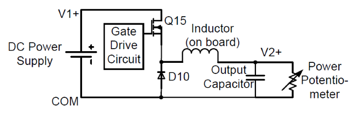
While it is simple to step up or down AC voltages and currents using transformers, stepping up or down DC voltages and currents in an efficient and regulated manner requires switching power converters. The DC/DC buck converter chops the input DC voltage using a series input switch, and the chopped voltage is filtered through the L-C low-pass filter to extract the average output voltage. The diode provides a path for the inductor current when the switch is off for part of the switching period. The output voltage is this less than or equal to the input voltage.
The objective of this experiment is to study different characteristics of a buck converter. The step-down capability of the converter will be observed under continuous conduction mode (CCM) where the inductor current is non-zero. Open-loop operation with a manually-set duty ratio will be used. An approximation of the input-output relationship will be observed.
This experiment will utilize the DC-DC converter board provided by HiRel Systems. http://www.hirelsystems.com/shop/Power-Pole-Board.html
Information about the board operation can be found in this collections video “Introduction to the HiRel Board.”
The procedure shown here applies to any simple buck converter circuit that can be built on proto boards, bread boards, or printed circuit boards.
1. Board setup
- Connect
It is expected the output-input voltage relationship of an ideal buck converter to be related to the duty cycle or duty ratio D. If the input voltage is Vin and the output voltage is Vout, Vout/Vin = D, where 0≤D≤ 100%. Therefore, for an input voltage of 24 V, Vout≈ 12 V for D = 50%, Vout≈ 7.2 V for D = 30%,
Buck converters are very common in electronic device chargers where they provide excellent voltage regulation required for battery charging. They are commonly used in power supplies that power computers, integrated circuits and electronic boards, as well as in renewable energy applications and battery fed systems.
건너뛰기...
이 컬렉션의 비디오:

Now Playing
DC/DC Buck Converter
Electrical Engineering
21.0K Views

전기 안전 주의사항 및 기본 장비
Electrical Engineering
144.4K Views

마그네틱 부품 특성
Electrical Engineering
14.9K Views

파워 폴 보드 소개
Electrical Engineering
12.4K Views

DC/DC 부스트 컨버터
Electrical Engineering
56.5K Views

플라이백 컨버터
Electrical Engineering
13.2K Views

단상 변압기
Electrical Engineering
20.1K Views

단상 정류기
Electrical Engineering
23.3K Views

사이리스터 정류기
Electrical Engineering
17.4K Views

단상 인버터
Electrical Engineering
17.9K Views

DC 모터
Electrical Engineering
23.3K Views

AC 인덕션 모터 특성
Electrical Engineering
11.6K Views

VFD 공급 AC 유도 장치
Electrical Engineering
6.9K Views

AC 동기식 장치 동기화
Electrical Engineering
21.5K Views

AC 동기식 장치 특성
Electrical Engineering
14.2K Views
Copyright © 2025 MyJoVE Corporation. 판권 소유