
Aby wyświetlić tę treść, wymagana jest subskrypcja JoVE. Zaloguj się lub rozpocznij bezpłatny okres próbny.
Method Article
Fabrication of Silica Ultra High Quality Factor Microresonators
W tym Artykule
Podsumowanie
We describe the use of a carbon dioxide laser reflow technique to fabricate silica resonant cavities, including free-standing microspheres and on-chip microtoroids. The reflow method removes surface imperfections, allowing long photon lifetimes within both devices. The resulting devices have ultra high quality factors, enabling applications ranging from telecommunications to biodetection.
Streszczenie
Whispering gallery resonant cavities confine light in circular orbits at their periphery.1-2 The photon storage lifetime in the cavity, quantified by the quality factor (Q) of the cavity, can be in excess of 500ns for cavities with Q factors above 100 million. As a result of their low material losses, silica microcavities have demonstrated some of the longest photon lifetimes to date1-2. Since a portion of the circulating light extends outside the resonator, these devices can also be used to probe the surroundings. This interaction has enabled numerous experiments in biology, such as single molecule biodetection and antibody-antigen kinetics, as well as discoveries in other fields, such as development of ultra-low-threshold microlasers, characterization of thin films, and cavity quantum electrodynamics studies.3-7
The two primary silica resonant cavity geometries are the microsphere and the microtoroid. Both devices rely on a carbon dioxide laser reflow step to achieve their ultra-high-Q factors (Q>100 million).1-2,8-9 However, there are several notable differences between the two structures. Silica microspheres are free-standing, supported by a single optical fiber, whereas silica microtoroids can be fabricated on a silicon wafer in large arrays using a combination of lithography and etching steps. These differences influence which device is optimal for a given experiment.
Here, we present detailed fabrication protocols for both types of resonant cavities. While the fabrication of microsphere resonant cavities is fairly straightforward, the fabrication of microtoroid resonant cavities requires additional specialized equipment and facilities (cleanroom). Therefore, this additional requirement may also influence which device is selected for a given experiment.
Introduction
An optical resonator efficiently confines light at specific wavelengths, known as the resonant wavelengths of the device. 1-2 The common figure of merit for these optical resonators is the quality factor or Q. This term describes the photon lifetime (τo) within the resonator, which is directly related to the resonator's optical losses. Therefore, an optical resonator with a high Q factor has low optical losses, long photon lifetimes, and very low photon decay rates (1/τo). As a result of the long photon lifetimes, it is possible to build-up extremely large circulating optical field intensities in these devices. This very unique property has allowed these devices to be used as laser sources and integrated biosensors.10
A unique sub-class of resonators is the whispering gallery mode optical microcavity. In these devices, the light is confined in circular orbits at the periphery. Therefore, the field is not completely confined within the device, but evanesces into the environment. Whispering gallery mode optical cavities have demonstrated some of the highest quality factors of any optical resonant cavity to date.9,11 Therefore, these devices are used throughout science and engineering, including in fundamental physics studies and in telecommunications as well as in biodetection experiments. 3-7,12
Optical microcavities can be fabricated from a wide range of materials and in a wide variety of geometries. A few examples include silica and silicon microtoroids, silicon, silicon nitride, and silica microdisks, micropillars, and silica and polymer microrings.13-17 The range in quality factor (Q) varies as dramatically as the geometry. Although both geometry and high Q are important considerations in any field, in many applications, there is far greater leverage in boosting device performance through Q enhancement. Among the numerous options detailed previously, the silica microsphere and the silica microtoroid resonator have achieved some of the highest Q factors to date.1,9 Additionally, as a result of the extremely low optical loss of silica from the visible through the near-IR, both microspheres and microtoroids are able to maintain their Q factors over a wide range of testing wavelengths.18 Finally, because silica is inherently biocompatible, it is routinely used in biodetection experiments.
In addition to high material absorption, there are several other potential loss mechanisms, including surface roughness, radiation loss, and contamination loss.2 Through an optimization of the device size, it is possible to eliminate radiation losses, which arise from poor optical field confinement within the device. Similarly, by storing a device in an appropriately clean environment, contamination of the surface can be minimized. Therefore, in addition to material loss, surface scattering is the primary loss mechanism of concern.2,8
In silica devices, surface scattering is minimized by using a laser reflow technique, which melts the silica through surface tension induced reflow. While spherical optical resonators have been studied for many years, it is only with recent advances in fabrication technologies that researchers been able to fabricate high quality silica optical toroidal microresonators (Q>100 million) on a silicon substrate, thus paving the way for integration with microfluidics.1
The present series of protocols details how to fabricate both silica microsphere and microtoroid resonant cavities. While silica microsphere resonant cavities are well-established, microtoroid resonant cavities were only recently invented.1 As many of the fundamental methods used to fabricate the microsphere are also used in the more complex microtoroid fabrication procedure, by including both in a single protocol it will enable researchers to more easily trouble-shoot their experiments.
Protokół
1. Microsphere Fabrication
- Select a small amount (approximately 5 inches) of optical fiber, strip ~1.5" cladding from one end and clean with either methanol or ethanol (Figure 1a, b).
- If available, cleave the end with an optical fiber cleaver. If not available, cut with wire cutters or scissors such that ~0.5" is left. The advantage of using an optical fiber cleaver is that it produces a very smooth, uniform cut as in Figure 1b. Excessive roughness or defects from a cut may cause uneven reflow, lowering the quality factor of the resulting spheres.
- Expose the cleaned fiber end to 3W of CO2 laser power focused to a ~500μm diameter spot size for ~1 second (Figure 1c, d, e). This produces spheres ~200μm in diameter; however, the size can be tuned by increasing or decreasing the diameter of the optical fiber. Slightly adjusting the laser intensity may also be necessary to reflow larger or smaller spheres.
2. Microtoroid Fabrication
- Design and make a photomask with dark, solid circles, in the spacing and diameter of your choice. It is important to note that the toroids produced will be 25-30% smaller than the circles on the mask. For example, a solid circle with a diameter of 100 microns will produce a toroid with a diameter of approximately 75 microns. Also, it is recommended to leave at least 1-2mm of space between each circle and at least 5mm of space between arrays of circles and around the edges of the mask. Since the sample wafers must be carefully handled with tweezers, it is important to leave space for the tweezers to grip without damaging the toroids. The extra space also provides room for a tapered optical fiber to couple light into the finished devices, and allows samples to be cut into smaller arrays more easily. For this procedure, we used a mask with rows of 160 μm diameter circles ~1mm apart, with ~5mm of space between each row of circles. The finished toroids are approximately 110 μm in diameter.
- Begin with silicon wafers with a 2 μm thick layer of thermally grown silica. Cleave the wafers to fit the desired microdisk pattern on the photolithography mask, leaving room for photoresist edge bead. Note that at the beginning of fabrication, it is usually most convenient to etch several arrays of circles on larger pieces of silicon wafers (~several cm x several cm). Larger wafers allow photolithography and BOE etching of more samples at a time, and are more easily handled with tweezers. Later, before the XeF2 etching step, it is recommended to cleave the larger wafers into smaller arrays to allow faster, more uniform XeF2 etching.
- In a fumehood, thoroughly clean the wafers by rinsing with acetone, methanol, isopropanol, and deionized water. Blow the samples dry using a nitrogen or filtered compressed air gun, and place them on a hot plate set to 120°C for at least 2 minutes to dry.
- After letting the wafers cool, place them in a flammable/solvent fumehood and expose to HMDS for 2 minutes using the vapor deposition method. A simple vapor deposition method: put a few drops of HMDS in a small 10ml beaker, and then cover the wafers and small beaker with a larger glass container to hold the vapor.
- Place a sample on a spinner with an appropriately sized mount. Using a dropper bottle or syringe and filter, apply photoresist to the sample. Spin coat S1813 photoresist onto each sample for 5 seconds at 500rpm, followed by 45 seconds at 3000rpm. Edge bead removal is not needed if the wafer is sufficiently large so that the edge bead does not interfere with the patterning.
- Soft bake the photoresist on a hot plate at 95°C for 2 minutes.
- Using a UV mask aligner and the desired photomask, expose the photoresist-covered samples to a total of 80mJ/cm2 of UV radiation.
- Immerse the samples in MF-321 developer to remove the photoresist which was exposed to UV light. While developing, closely watch as the photoresist is removed from the wafer and dissolved. It is important to stir/swish the container constantly during this process to ensure the photoresist is removed uniformly. For the given parameters, the photoresist takes approximately 30 seconds to develop.
- When most of the unwanted photoresist has dissolved in the developer, rinse the samples thoroughly under running water, gently blow dry the samples using a nitrogen or air gun, and inspect the samples with a microscope to ensure all undesired photoresist has been removed. If needed, the samples can be immersed again in developer; however, one should be careful not to overdevelop the samples as the desired photoresist patterns could also be damaged. (If the desired patterns are damaged or defective, the photoresist can be removed with acetone and steps 2.1-2.9 can be repeated again).
- After developing, thoroughly rinse the samples in running water, gently blow dry the samples, and hard bake them on a hot plate at 110°C for 2 minutes. This step heats the photoresist above its glass transition temperature, reflowing the photoresist and partially repairing roughness which occurred during the developing process.
- Using Teflon containers and the necessary protective equipment, immerse the samples in improved buffered oxide etchant (BOE). BOE contains HF, which etches the silica not covered by photoresist to form circular silica pads on the silicon wafer (Figure 2a-c). Improved buffered HF produces a smoother etch, minimizing roughness in the resulting silica circles. While it is possible to mix buffered HF starting with 49% HF, this can lead to highly variable results as typically only small quantities are made.
- After approximately 15-20 minutes (depending on the patterns, sample sizes and number of samples), remove the samples from the BOE using Teflon tweezers. Carefully rinse the samples in running water. The silica has been removed when the samples become hydrophobic.
- After etching, rinsing, and drying the samples, inspect them using an optical microscope. Check to make sure the desired patterns have been etched completely and all the unwanted silica has been removed. If needed, return the samples to the BOE for further etching. One should be careful not to overetch the samples, or the circular patterns underneath the photoresist may be damaged.
- Once BOE etching is complete, thoroughly rinse the samples in deionized water and blow dry. If the samples are on large pieces of silicon wafer, it is also recommended to cut them (using a dicing saw or diamond scribe) into smaller pieces with individual rows of silica circles. Individual rows of circles are etched more quickly and uniformly in the XeF2 etching step (2.16). Silicon dust produced by the cutting is removed during cleaning in the next step.
- Remove the photoresist by rinsing with acetone, methanol, isopropanol, and deionized water, and dry the samples using a nitrogen gun and heating on a 120°C hot plate for at least 2 minutes.
- Using a XeF2 etcher, undercut the silicon beneath the circular silica pads to form silica microdisks (Figure 2d-f). The amount etched should be approximately 1/3 of the silica circle’s size, so that the resulting microdisk’s pillar is approximately 1/3-1/2 of the total disk diameter, as determined by inspection with an optical microscope. The number of XeF2 pulses and the duration of each pulse depends on the amount of silicon in the chamber and the type of XeF2 etcher used.
- After XeF2 etching, expose the samples to a focused CO2 laser beam at approximately 12W intensity for ~3 seconds or until a smooth toroid is formed (Figure 2g-i). Depending on the exact size of the disk and the amount of XeF2 undercut, a slightly higher or lower intensity and exposure time may be needed to form a microtoroid. It is important that the center of the laser beam and the center of the microdisk are aligned, so that the silica microdisk will form a smooth, circular microtoroid.
3. Representative Results
The microsphere and microtoroid devices can be imaged using both optical microscopy and scanning electron microscopy (Figure 1d, e and Figure 2h, i). In all images, the uniformity of the device surface is clearly evident.
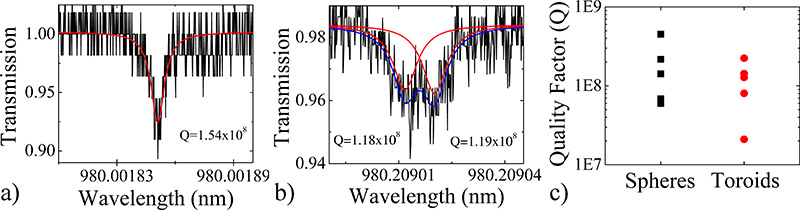
To verify that the detailed approach creates ultra-high-Q devices, we also characterized the Q factor of several devices by performing a linewidth (Δλ) measurement and calculating the loaded Q from the simple expression: Q=λ/Δλ=ωτ, where λ=resonant wavelength, ω=frequency, and τ=photon lifetime. Representative spectra of each device fabricated using the previously detailed procedures1,9 and a comparison graph of several devices is shown in Figure 3. The quality factors of all devices are above 10 million, with the majority being above 100 million.
The spectrum of the microsphere was a single resonance, indicating that the light coupled into either the clockwise or counter-clockwise propagating optical mode. However, the spectrum of the toroid exhibited a split resonance, indicating that light coupled into both the clockwise and counter-clockwise modes simultaneously. This phenomenon occurs when there is a slight imperfection at the coupling site. By fitting the spectrum to a dual-Lorentzian, the Q factor of both modes can be determined. The split resonance phenomena can occur in both sphere and toroid resonators, but is more frequently observed in toroids as they are more susceptible to imperfections and have fewer optical modes compared to spheres.

Figure 1. Flow chart of the microsphere cavity fabrication process. a) Rendering and b) optical micrograph of a cleaned and cleaved optical fiber. c) Rendering, d) optical micrograph and e) scanning electron micrograph of a microspere resonator.

Figure 2. Flow chart of the microtoroid cavity fabrication process. a) Rendering, b) top-view optical micrograph and c) side-view scanning electron micrograph of the circular oxide pad, as defined by photolithography and BOE etching. Note the slight wedge-shape of the oxide that is formed by the BOE. d) Rendering, e) top-view optical micrograph and f) side-view scanning electron micrograph of the oxide pad after the XeF2 etching step. Note that the oxide disk maintains the wedge-shaped periphery. g) Rendering, h) top-view optical micrograph and i) side-view scanning electron micrograph of the microtoroid cavity.

Figure 3. Representative quality factor spectra of the a) microsphere and b) microtoroid resonant cavities as determined using the linewidth measurement method. In very high Q devices, one may observe mode-splitting or a double peak, in which light reflects off a small defect and circulates in both clockwise and counterclockwise directions. c) Comparison graph showing the Q factors of several microsphere and microtoroid resonant cavities. Click here for larger figure.

Figure 4. Schematic of the CO2 laser reflow set-up. The CO2 laser beam (solid blue line) is reflected and then focused on the sample. It passes through the 10.6 μm / 633 nm beam combiner, which transmits 10.6 μm and reflects 633 nm. The optical column images the reflection of the sample off of the beam combiner; therefore, the image is somewhat red. A list of the necessary parts for this setup is in Table 4.

Figure 5. Incorrectly reflowed a) microsphere and b) microtoroid resonant cavities. Due to incorrect placement within the beam, the device is mal-formed. c) As a result of a poor photomask or poor lithography, the toroid is moon-shaped.
Dyskusje
As with any optical structure, maintaining cleanliness at every step of the fabrication process is of critical importance. As there are numerous textbooks written on the topic of lithography and fabrication, the suggestions below are not intended to be comprehensive, but highlight a few of the more common issues researchers have faced.19-20
Because the uniformity of the microtoroid's periphery is determined by the uniformity of the initial disk, it is very important to pattern very ...
Ujawnienia
No conflicts of interest declared.
Podziękowania
A. Maker was supported by an Annenberg Foundation Graduate Research Fellowship, and this work was supported by the National Science Foundation [085281 and 1028440].
Materiały
| Name | Company | Catalog Number | Comments |
| Fiber scribe | Newport | F-RFS | Optional |
| Optical fiber | Newport | F-SMF-28 | Any type of optical fiber can be used. |
| Fiber coating stripper | Newport | F-STR-175 | Wire strippers can also be used |
| Ethanol | Any vendor | Solvent-level purity | Methanol or Isopropanol are substitutes |
| Table 1. Microsphere Fabrication Materials. | |||
| Silicon wafers with 2μm thermally grown silica | WRS Materials | n/a | We use intrinsic8, <100>, 4" diameter |
| HMDS (Hexamethyldisilazane) | Aldrich | 440191 | |
| Photoresist | Shipley | S1813 | |
| Developer | Shipley | MF-321 | |
| Buffered HF - Improved | Transene | n/a | The improved buffered HF gives a smoother, better quality etch than plain B– or HF |
| Acetone, Methanol, Isopropanol | Any vendor | 99.8% purity | |
| Table 2. Microtoroid Fabrication Materials. | |||
| Spinner | Solitec | 5110-ND | Any spinner can be used. |
| Aligner | Suss Microtec | MJB 3 | Any aligner can be used. |
| XeF2 etcher | Advanced Communication Devices, Inc. | #ADCETCH2007 | |
| Table 3. Microtoroid Fabrication Equipment. | |||
| CO2 Laser | Synrad | Series 48 | |
| 3-Axis stage | OptoSigma | 120-0770 | Available from other vendors as well. |
| Si Reflector 1" diameter) | II-VI | 308325 | Available from other vendors as well. |
| Kinematic gimbal mount (for Si reflector) | Thor Labs | KX1G | Available from other vendors as well. |
| Beam combiner (1" diameter) | Meller Optics | L19100008-B0 | Available from other vendors as well. |
| 4" Focal length Lens (1" diameter) | Meller Optics or II-VI | Available from other vendors as well | |
| Assorted posts, lens mounts | Thor Labs, Newport, Edmund Optics or Optosigma | ||
| Zoom 6000 machine vision system | Navitar | n/a | Requires generic USB camera and computer for real-time imaging. This is purchased as a kit. |
| Focuser for Zoom 6000 system | Edmund Optics | 54-792 | Available from other vendors as well. |
| X-Z Axis Positioners for Zoom 6000 | Parker Daedal | CR4457, CR4452, 4499 | CR4457 is X-axis, CR4452 is Z-axis, 4499 is mounting bracket. |
| Table 4. CO2 Laser Reflow Set-up. | |||
Odniesienia
- Armani, D. K., Kippenberg, T. J., Spillane, S. M., Vahala, K. J. Ultra-high-Q toroid microcavity on a chip. Nature. 421, 925-928 (2003).
- Gorodetsky, M. L., Savchenkov, A. A., Ilchenko, V. S. Ultimate Q of optical microsphere resonators. Optics Letters. 21, 453-455 (1996).
- Armani, A. M., Kulkarni, R. P., Fraser, S. E., Flagan, R. C., Vahala, K. J. Label-Free, Single-Molecule Detection with Optical Microcavities. Science. 317, 783 (2007).
- Choi, H. S., Ismail, S., Armani, A. M. Studying polymer thin films with hybrid optical microcavities. Optics Letters. 36, 2152-2154 (2011).
- Aoki, T. Observation of strong coupling between one atom and a monolithic microresonator. Nature. 443, 671-674 (2006).
- Hsu, H. -. S., Cai, C., Armani, A. M. Ultra-low threshold Er:Yb sol-gel microlaser on silicon. Optics Express. 17, 23265 (2009).
- Zhu, J. On-chip single nanoparticle detection and sizing by mode splitting in an ultrahigh-Q microresonator. Nature Photonics. 4, 46-49 (2009).
- Zhang, X., Choi, H. -. S., Armani, A. M. Ultimate quality factor of silica microtoroid resonant cavities. Applied Physics Letters. 96, 153304 (2010).
- Vernooy, D. W., Ilchenko, V. S., Mabuchi, H., Streed, E. W., Kimble, H. J. High-Q measurements of fused-silica microspheres in the near infrared. Optics Letters. 23, 247-249 (1998).
- Saleh, B. E. A., Teich, M. C. . Fundamentals of Photonics. , (2007).
- Ilchenko, V. S. Crystal quartz optical whispering-gallery resonators. Optics Letters. 33, 1569-1571 (2008).
- Soteropulos, C., Hunt, H., Armani, A. M. Determination of binding kinetics using whispering gallery mode microcavities. Applied Physics Letters. 99, 103703 (2011).
- Barclay, P. E., Srinivasan, K., Painter, O., Lev, B., Mabuchi, H. Integration of fiber-coupled high-Q SiNx microdisks with atom chips. Applied Physics Letters. 89, (2006).
- Srinivasan, K., Painter, O. Mode coupling and cavity-quantum-dot interactions in a fiber-coupled microdisk cavity. Physical Review. A. 75, (2007).
- Xu, Q. F., Lipson, M. All-optical logic based on silicon micro-ring resonators. Optics Express. 15, 924-929 (2007).
- Martin, A. L., Armani, D. K., Yang, L., Vahala, K. J. Replica-molded high-Q polymer microresonators. Optics Letters. 29, 533-535 (2004).
- Chao, C. Y., Guo, L. J. Polymer microring resonators fabricated by nanoimprint technique. Journal of Vacuum Science Technology B. 20, 2862-2866 (2002).
- Armani, A. M., Armani, D. K., Min, B., Vahala, K. J., Spillane, S. M. Ultra-high-Q microcavity operation in H2O and D2O. Applied Physics Letters. 87, 151118 (2005).
- Kovacs, G. T. A. . Micromachined Transducers Sourcebook. , (1998).
- Kovacs, G. T. A., Maluf, N. I., Petersen, K. E. Bulk Micromaching of Silicon. Proceedings of the IEEE. 86, 1536-1551 (1998).
Przedruki i uprawnienia
Zapytaj o uprawnienia na użycie tekstu lub obrazów z tego artykułu JoVE
Zapytaj o uprawnieniaPrzeglądaj więcej artyków
This article has been published
Video Coming Soon
Copyright © 2025 MyJoVE Corporation. Wszelkie prawa zastrzeżone