
Thyristor Rectifier
Przegląd
Source: Ali Bazzi, Department of Electrical Engineering, University of Connecticut, Storrs, CT.
Similar to diodes, thyristors, also called silicon controlled rectifiers (SCRs), pass current in one direction from the anode to cathode, and block current flow in the other direction. However, current passage can be controlled through a "gate" terminal, which requires a small current pulse to turn on the thyristor so it can start conducting.
Thyristors are four-layer devices, composed of alternating layers of n-type and p-type material, thereby forming PNPN structures with three junctions. The thyristor has three terminals; with the anode connected to the p-type material of the PNPN structure, the cathode connected to the n-type layer, and the gate connected to the p-type layer nearest the cathode.
The objective of this experiment is to study a controlled thyristor-based half-wave rectifier at different conditions, and understand how different timings of the gate pulse affect the DC output voltage.
Zasady
The thyristor only conducts under the same conditions as a diode, in addition to the condition of having a gate pulse to trigger the conduction process. For example, if an AC source is connected in series with a thyristor and a resistive load, the positive half-cycle of the source is not enough to forward bias the thyristor; the thyristor will remain reverse biased or off until a gate pulse is applied. It will then start conducting during that half-cycle. Thus, the thyristor has three terminals, the anode (A), cathode (K), and gate (G). Gate pulses are generated by "gate drive" circuits that drive current into the gate. The delay between the AC source zero crossing the gate pulse command is termed the "firing angle" which is an electrical angle.
Fig.1 shows a simple half-wave thyristor rectifier circuit with a pulse generating circuit (R1, R2, D1, D2, and C) that generates current pulses at the thyristor's gate. When the pulse is available and is "fired" at a firing angle which is a certain delay period from the zero crossing of the input voltage Vin, the thyristor acts like a diode in terms of passing current in one direction. Once the current goes to zero and the gate pulse is not available, the thyristor will remain off until the current is positive again and a gate pulse is fired.
In this experiment, we will study a controlled thyristor-based half-wave rectifier at different firing angles. The average output voltages for different angles are compared to study the effect of controlling the turn-on time on the average DC output voltage.
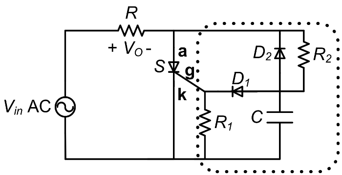
Figure 1: Half-wave rectifier with SCR and resistive load.
Procedura
ATTENTION: During this experiment, do not touch any part of the circuit while energized. Do NOT ground the VARIAC.
For this experiment, the variable transformer (VARIAC) at a low frequency of 60 Hz and peak of 35 V is used as the main AC source.
1. Setup
- Before starting, connect the differential probe to one scope channel.
- Set the button on the differential probe to 1/20 (or 20X) attenuation.
- On the scope channel menu, set the probe to be at 10X unless 20X is available for the differential probe. If 10X is chosen, manually multiply any measurements or results by two to reach the 20X desired.
- To setup the VARIAC, make sure the VARIAC output (looks like a regular receptacle) is not connected to any cable.
- Keep the VARIAC OFF and make sure its knob is set to zero.
- Slowly adjust the VARIAC knob to around 15% output.
- Before connecting the differential probe to the circuit, tie the probe's terminals together and adjust its measured waveform on the screen to show zero offset voltage.
- Connect the output cable to the VARIAC, and the differential voltage probe across the VARIAC output banana plugs.
- Turn the VARIAC ON.
- Slightly adjust the VARIAC to achieve 35V peak.
- Take a copy of Vin to use for reference. Show two to five fundamental cycles.
- Turn the VARIAC OFF. Do not adjust its knob setting for the rest of the experiment.
2. Half-Wave Rectifier SCR Circuit with Resistive Load and Zero Firing Angle
- The main rectifier component is the SCR (S), which is a TYN058. The load resistor (R) is 51 Ω. The SCR control circuit is enclosed in the dotted box of Fig. 1.
- The control circuit uses diodes (1N4004), a 1 kΩ resistor (R1), a control resistor that is manually changed (R2), and a ceramic (no polarity) 1 µF capacitor (C).
- Make sure the SCR and diode polarities are correct. The dash on the diode is at the cathode while the SCR pin assignment is shown in Fig. 2.
- On the proto board, build the circuit shown in Fig. 1. Use a short circuit instead of R2.
- Connect the differential voltage probe across the load resistor to observe the output voltage, Vout.
- Turn the VARIAC ON.
- Adjust the time base on the scope to show Vout for the same number of fundamental cycles that were captured for Vin. Make a copy of the waveforms.
- Measure the average or mean Vout.
- Zoom in between the SCR turn-off point and the next SCR turn-on point. Measure the time difference using the scope cursors. Make a copy of the waveform.
- Keep the differential probe connection and other circuit connections the same for the next part.
- Turn OFF the VARIAC. Do NOT change the VARIAC voltage setting.
Figure 2: Pin assignment of the SCR.
3. Half-Wave Rectifier SCR Circuit with Resistive Load and Non-Zero Firing Angle
Two different resistors will be used as R2. The values should be between 100 and 1000 Ω. The resistance can read the resistance color code, or measured with a digital multimeter.
- Angle Setting #1 (small R2)
- Remove the short circuit, which was previously used instead of R2.
- Connect the small resistance value for R2.
- Turn the VARIAC ON.
- Adjust the time base on the scope to show Vout for the same number of fundamental cycles captured for Vin. Make a copy of the waveforms.
- Measure the average or mean Vout.
- Zoom in between the SCR turn-off point and the next SCR turn-on point. Measure the time difference using the scope cursors. Make a copy of the waveform.
- Keep the differential probe connection and other circuit connections the same for the next part.
- Turn OFF the VARIAC. Do NOT disassemble the circuit or change the VARIAC voltage setting.
- Angle Setting #2 (small R2)
- Replace R2 with the larger value resistor.
- Turn the VARIAC ON.
- Adjust the time base on the scope to show Vout for the same number of fundamental cycles captured for Vin. Make a copy of the waveforms.
- Measure the average or mean Vout.
- Zoom in between the SCR turn-off point and the next SCR turn-on point. Measure the time difference using the scope cursors. Make a copy of the waveform. The mean value should be what is expected from this equation:
<Vout>=V0[1+cos(α)]/(2π) (1)
which is slightly less than half the peak voltage of the input. - Turn OFF the VARIAC. Disassemble the circuit and return the VARIAC setting to zero.
Wyniki
The AC input voltage waveform is chopped until the firing angle. Important relationships of the average output voltage and firing angles for different SCR rectifiers with input Vin= V0 cos(ωt) are:
• Single SCR and R load: <Vout>=V0[1+cos(α)]/(2π) (2)
• SCR bridge and R load: <Vout>= V0[1+cos(α)]/π (3)
• SCR bridge, current source load: <Vout>=2V0 cos(α)/π (4)
As the firing angle increases, the mean or DC voltage at the output decreases as the output voltage waveform across the resistive load is a chopped version of the input.
Wniosek i Podsumowanie
SCR's were common in older DC power supplies that required a variable DC output voltage from an AC input. By adjusting the resistor R2 in the above circuit, it is possible to adjust the average Vout and therefor an adjustable DC power supply results. SCRs are not common any more in DC power supplies as they switch at the input line frequency (typically 50 or 60 Hz), and new power supplies switch at 10 s or 100 s of kHz which makes filtering the output voltage to extract the DC component much easier with smaller capacitors. However, SCRs are still common in high voltage inverters where the switching frequency can be low at the line frequency since many high voltage and high current SCR's are available in the market.
Przejdź do...
Filmy z tej kolekcji:

Now Playing
Thyristor Rectifier
Electrical Engineering
17.6K Wyświetleń

Electrical Safety Precautions and Basic Equipment
Electrical Engineering
144.8K Wyświetleń

Characterization of Magnetic Components
Electrical Engineering
15.1K Wyświetleń

Introduction to the Power Pole Board
Electrical Engineering
12.5K Wyświetleń

DC/DC Boost Converter
Electrical Engineering
57.1K Wyświetleń

DC/DC Buck Converter
Electrical Engineering
21.2K Wyświetleń

Flyback Converter
Electrical Engineering
13.3K Wyświetleń

Single Phase Transformers
Electrical Engineering
20.2K Wyświetleń

Single Phase Rectifiers
Electrical Engineering
23.5K Wyświetleń

Single Phase Inverter
Electrical Engineering
18.0K Wyświetleń

DC Motors
Electrical Engineering
23.5K Wyświetleń

AC Induction Motor Characterization
Electrical Engineering
11.7K Wyświetleń

VFD-fed AC Induction Machine
Electrical Engineering
7.0K Wyświetleń

AC Synchronous Machine Synchronization
Electrical Engineering
21.6K Wyświetleń

AC Synchronous Machine Characterization
Electrical Engineering
14.3K Wyświetleń
Copyright © 2025 MyJoVE Corporation. Wszelkie prawa zastrzeżone