A Tactile Automated Passive-Finger Stimulator (TAPS)
In This Article
Summary
We describe a computer-controlled device for investigating the sense of touch: the Tactile Automated Passive-finger Stimulator (TAPS). We describe the components of TAPS, and show how TAPS is used to administer a two-interval forced-choice tactile grating orientation test.
Abstract
Although tactile spatial acuity tests are used in both neuroscience research and clinical assessment, few automated devices exist for delivering controlled spatially structured stimuli to the skin. Consequently, investigators often apply tactile stimuli manually. Manual stimulus application is time consuming, requires great care and concentration on the part of the investigator, and leaves many stimulus parameters uncontrolled. We describe here a computer-controlled tactile stimulus system, the Tactile Automated Passive-finger Stimulator (TAPS), that applies spatially structured stimuli to the skin, controlling for onset velocity, contact force, and contact duration. TAPS is a versatile, programmable system, capable of efficiently conducting a variety of psychophysical procedures. We describe the components of TAPS, and show how TAPS is used to administer a two-interval forced-choice tactile grating orientation test.
Corresponding Author: Daniel Goldreich
Protocol
Introduction
The Tactile Automated Passive-Finger Stimulator (TAPS) is a computer-controlled system that presses structured surfaces against the skin in order to assess a person's tactile spatial acuity. We designed and constructed the device in Duquesne University, and modified it to its current form in McMaster University. Here, we provide an overview of the function of TAPS. We then describe the components of the device, in order to facilitate its reproduction by other researchers. Finally, we show how TAPS is used to conduct a psychophysical experiment.
1. Device Overview
TAPS uses gravity to press a stimulus surface against the skin (Fig. 1). The subject's arm rests comfortably in prone position on a tabletop. The fingertip (or other skin area to be tested) lies over a tunnel in the table. Beneath the table, a stepper motor rotates a disk that holds up to 40 stimulus pieces, positioning one of the pieces under the tunnel. Gravity exerts a downward force on a mass hanging from one end of a rotatable rod. A crossbar extending from the carriage of a linear actuator prevents the rod from moving. As the actuator motors forward, the rod pivots under the influence of gravity, pressing a stimulus piece upward through the tunnel and onto the skin. Simple physics relates the speed of the actuator to the speed with which the stimulus surface rises to contact the skin, and the weight of the hanging mass to the static force of the tactile stimulus. As the actuator reverses direction to return the rod to its starting position, the stimulus piece drops. Thus, the device applies tactile stimuli with controlled force, velocity, contact duration, and inter-stimulus interval. The subject selects a button with the non-tested hand to register a response. TAPS detects the response and proceeds to deliver the next stimulus.

Figure 1. The Physics of TAPS. TAPS controls both the onset velocity and the steady-state force of the stimulus.
Onset velocity: As the crossbar from the linear actuator (red) moves to the right with velocity V1, the left end of the rotating rod drops under the influence of gravity; the right end of the rod therefore presses a stimulus piece upwards towards the finger with velocity V2 = V1 (L2 / L3). Since V1 is under computer control, V2 may be set to any value desired by the investigator.
Force: Gravity exerts a downward force, F1 = Mg, on the mass M (where g = 9.8 m/s2). This causes the stimulus piece to press against the finger with an upward force, F2. For a massless rod, F2 = F1 ( L1 / L2). Since the rod is not in fact massless, F2 is determined empirically, by measurement with a force sensor. To make fine adjustments to F2, the investigator can change the position of M along the rod. F2 increases slightly as M is moved to the left (increasing L1), and decreases slightly as M is moved to the right (decreasing L1). To make larger adjustments to F2, the mass can be changed.
2. Components and Details of Device Function
i. Moving Parts
TAPS uses two stepper motors, one to drive the carriage of the linear actuator, and another to rotate the disk containing the stimulus pieces. These two motors control all of TAPS' moving parts. These parts lie on a lower table that is mechanically uncoupled from the upper table on which the subject's arm rests. Because the two tables are uncoupled, vibrations caused by the motors do not transfer to the skin. The tables are carefully aligned so that the tunnel through the upper table lies directly above the stimulus piece contacted by the rotating rod.
We machined 40 square slots around the circumference of the rotating disk, to accommodate the stimulus pieces. We constructed stimulus pieces from round plastic rods, machining the rods to have square shafts that fit into the slots of the disk. This ensures that the pieces do not rotate within their slots as the disk spins. We cut the stimulus surfaces into the round faces of the pieces.
When the actuator carriage motors forward, the end of the rotating rod opposite the hanging mass rises to contact the bottom of the selected stimulus piece. Because the rod describes an arc as it swings upwards, it is fit with a lightweight plastic bearing wheel to eliminate friction with the bottom of the stimulus piece. This plastic wheel rotates slightly as it pushes the stimulus piece upward; without the plastic wheel, the end of the rod would pull the base of the piece slightly laterally (towards the left in Fig. 1), causing the piece to jam within the tunnel through the upper table. To further ensure a smooth upward trajectory of the piece, the tunnel is fit with a plastic collar that is beveled to direct the piece towards the center of the tunnel as the piece rises.
ii. Sensors
TAPS makes use of six sensors to ensure proper functioning: two home sensors, three limit sensors, and a force sensor.
The actuator and disk home sensors signal to the computer that the actuator carriage and the disk are in their desired initial positions at the start of an experiment. The actuator home sensor is a Hall-effect sensor; the disk home sensor is a U-shaped photoelectric sensor, activated when a piece of stiff paper glued to the disk rim breaks the infrared sensor beam. When the disk is in home position, a particular slot is aligned directly under the tunnel in the upper table. All subsequent disk movement calculations are made relative to this known starting position.
The three limit sensors serve as safety features in case of malfunction. To prevent runaway movement of the actuator carriage in the unlikely event of a control malfunction, the actuator is fit with forward and reverse limit sensors (Hall-effect sensors). If activated, these cut power to the actuator. To prevent disk movement in the event that a stimulus piece becomes stuck in the tunnel, an infrared retro-reflective sensor is attached to the underside surface of the upper table. A piece that is elevated sufficiently to enter the tunnel breaks the infrared beam cast by this sensor, and blocks command voltages from reaching the disk stepper motor.
The sixth and final sensor is a force sensor that rests gently on the subject's fingernail (Fig. 2). This sensor detects downward (into the tunnel), backward or forward finger movement. The program discards trials in which movement occurred. Because the sensor is attached to a rigid arm, it additionally prevents the finger from moving passively upwards upon contact with the rising piece. Since we use TAPS to test passive (finger stationary) tactile spatial acuity, the force sensor is a crucial element. As a final precaution against finger movement, we place plastic barriers gently against the sides of the finger to prevent lateral movements.

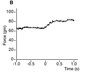
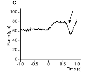
Figure 2. Force Sensor to detect finger movement. A. The force sensor presses at 90-deg to the surface of the fingernail, near the cuticle, with a force between 50 and 80 grams. B. Example force sensor trace showing one second preceding contact of the stimulus piece with the finger, followed by one second of maintained contact with the stationary finger. Note that, upon contact (time = 0), the force of the stimulus piece from below pushes the finger more firmly up against the sensor (rising slope in force trace). C. If the subject attempts to move the finger downward to better feel the stimulus surface, then the force between the fingernail and the sensor diminishes (arrow). The sensor also registers force fluctuations if the subject moves the finger backwards or forwards. TAPS is programmed to discard any trials in which the force of contact between the sensor and the fingernail fluctuates by more than a threshold amount (e.g., 20 grams) while the skin is in contact with the stimulus surface. Using a computer-generated voice, TAPS can optionally warn the subject that movement was detected.
iii. Vibration and Sound Damping
TAPS' stepper motors produce vibration, and this in turn causes sound. Both vibration and sound are undesirable. Vibration, if transmitted to the skin, could interfere with the subject's ability to perform the tactile task. Over time, vibration could also cause mechanical instability in TAPS' components. Sound could distract the subject. For these reasons, we have taken measures to reduce both vibration and sound, and to prevent any vibration from reaching the subject.
Most importantly, the lower and upper tables do not contact one another. They are connected only in the sense that they both contact the floor. Hence, vibration from the motors, which rest on the lower table, is not transmitted to the subject's arm, which rests on the upper table. Additionally, vibration and sound are reduced as follows: a fiberglass curtain enclosing the lower table muffles device sound; PVC/fiber reinforced anti-vibration pads sandwiched between the actuator and its base absorb some of the actuator-produced vibration; the actuator base sits on four rubber cylindrical sandwich mounts that serve to further dampen vibration; the disk stepper motor base also sits on rubber mounts (syringe plunger rubber); and silicone O-rings surround the shafts of the stimulus pieces, reducing clatter as the disk turns.
iv. Stimulus Pieces
TAPS uses modified half-inch diameter rods to press spatially structured surfaces against the skin (Fig. 3). The rods are machined to have square shafts. The round faces of the rods contain the stimulus surfaces; the square shafts of the rods fit into the 40 square slots around the circumference of the rotating disk, ensuring that the stimulus surfaces maintain their proper orientations as the disk spins.
Any stimulus surfaces may be machined into the rod faces. We have used TAPS mainly to apply square wave gratings (i.e., parallel ridges and grooves). To create these, we started with 0.5" diameter Delrin plastic cylindrical rods, 3" long. Using a Sherline milling machine, we cut the rods to 2.75" long, with 2" long square-cross-section shafts (8.7 x 8.7 mm), and a 0.75"-long, 12.74 mm diameter round cylindrical head. We then milled grooves in the round face to create the stimulus surfaces. Each stimulus surface has equal ridge and groove widths. We made pieces with groove widths ranging from 0.25 to 3.10 mm in 0.15 mm increments. We made two identical stimulus pieces for each of these 20 groove widths, resulting in 40 pieces total. We then inserted the pieces into the square slots of the disk such that each groove width was represented in both the vertical (parallel to long axis of the finger) and horizontal (transverse to the long axis of the finger) orientation.

Figure 3. Stimulus piece. Each stimulus surface is milled into the face of a 0.5-inch diameter Delrin rod. The base of the rod is cut to have a square cross section, allowing it to fit into the square cutouts in the rotating disk. The surface of the piece shown is a square-wave grating, with parallel grooves and ridges of equal width.
v. Computer Control
TAPS is a fully automated, computer-controlled system. Many computer hardware and software configurations could be used to control the device. We currently use a Macintosh G3 running LabVIEW 6.1 (National Instruments). The computer communicates via a motor controller board with a stepper motor driver to command the actuator and disk motors, and to read the home sensors and limit switches. A PCI data acquisition board reads the force sensor and subject response buttons.
vi. Force and Timing Limitations
Force range: We have used TAPS to deliver stimuli with forces ranging from 10 to 50 grams. We suspect that friction in the components would impede the delivery of stimuli at forces under about 5 grams, and that some mechanical instability would arise for forces in excess of about 100 grams.
Inter-stimulus interval (ISI): The distance between the stimulus surfaces and the finger, and the stable speeds of the linear actuator and disk stepper motor, together set a lower limit on the ISI that the device can achieve. We estimate this limit at about 1.5 seconds. Thus, the device is not appropriate for applications such as masking experiments, which require sub-second ISI.
3. Conducting an Experiment
Here we describe one protocol for which TAPS can be used: a two-interval forced-choice (2-IFC) grating orientation task (GOT) with Bayesian adaptive tracking. TAPS can be programmed for many other psychophysical protocols as well. We have used it previously to conduct 2-IFC experiments with staircase tracking1,2 and with the method of constant stimuli. Of course, it is able to conduct yes/no procedures as well as 2-IFC.
For the 2-IFC GOT task, we use square wave gratings that contact the distal pad of the finger with 4 cm/sec onset velocity, 50 gm contact force, and 1 sec contact duration. Each trial consists of two sequential stimulus presentations (ISI: 2 sec) with gratings of identical groove width, but differing 90-deg in orientation. In one presentation, the grooves are aligned vertically (parallel), and in the other, horizontally (transverse), to the long axis of the finger. Stimulus order is chosen randomly by the computer program. The subject indicates whether the horizontal orientation occurred in the first or second interval, by pressing one of two buttons with the non-tested hand. A Bayesian adaptive method adjusts groove width from trial to trial.
We programmed TAPS with a modified version of the psi (Ψ) method, a Bayesian adaptive algorithm3. This method has several advantages over conventional adaptive methods, such as staircase methods. First, the psi method estimates not just a single point on the psychometric function (e.g., the 71% threshold estimated by a 2-down 1-up staircase), but the entire psychometric function. Second, the method yields Bayesian posterior probability distributions (and thereby confidence intervals) for the parameters of the psychometric function. Finally, the method is efficient. It holds in memory many thousands of possible psychometric function shapes, and updates the posterior probability of each function after each response. It then uses an expected entropy minimization procedure to choose the next stimulus; that is, it chooses the stimulus on each trial that is expected to maximize the information gain.
Following Kontsevich and Tyler3, we modeled d-prime as a power function of stimulus level, and each subject's psychometric function – Pc(x), the probability of a correct response as a function of stimulus level, x – as a mixture of a cumulative normal (probit) function and a lapse rate term:


Here, a is the threshold (stimulus level corresponding to 76% correct response probability, d-prime = 1), and b is the slope, of the subject's psychometric function.
We modified the Ψ algorithm by treating the lapse rate (delta) as a parameter of unknown value, and by calculating a "guessing Bayes factor" after each trial:

This Bayes factor is a likelihood ratio that compares the probability of the data under hypothesis 1, that the subject is guessing, to the probability of the data under hypothesis 2, that the subject has a psychometric function. The numerator is the probability of the subject's data, D (correct and incorrect responses at each of the groove widths presented) given that the subject is simply guessing (50% probability correct) on all trials up to and including the current trial. The denominator is the probability of the data given the algorithm's best estimate of the subject's psychometric function. In our experience, for most young subjects the Bayes factor rapidly approaches zero as the testing block progresses, indicating that the subject's performance conforms to a psychometric function. For some older subjects, the Bayes factor rises above one, indicating that the subject is unable to perform the task. TAPS can be programmed to terminate the testing block if the guessing Bayes factor has exceeded a threshold value after a specified number of trials.
4. Results
Figure 4 shows an experimental block consisting of 40 trials from a 2-IFC GOT experiment. This 40-trial block consisted of 80 stimuli to the subject's right middle finger, with 1-second contact duration and 2-second ISI between contacts in a single trial. The subject's 76% correct threshold was 1.7 mm, as indicated by the mode of the posterior probability density function (PDF) for the threshold parameter (panel C). The 95% confidence interval for the subject's threshold parameter, indicated by the width of the posterior PDF, was 1.3 - 1.9 mm.
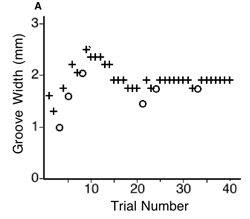
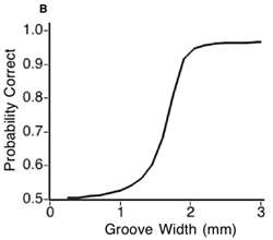
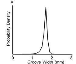
Figure 4. Results from a 2-interval forced-choice grating orientation task. A. An experimental block, consisting of 40 trials applied in this case to the right middle finger. The subject's correct (plus symbols) and incorrect (open circles) responses at different groove widths are plotted against trial number. A Bayesian adaptive method (see text) determined the sequence of groove widths to apply, based on the subject's performance. B. The best-fit psychometric function for this subject. C. Posterior probability density function for the subject's 76% correct groove width (psychometric function a-parameter, corresponding to d-prime = 1).
Discussion
The controlled delivery of spatially structured mechanical stimuli poses challenges not faced in the delivery of visual or auditory stimuli, for which commercially available equipment (computer screens, audio speakers) may be used. For this reason, many tactile psychophysics experiments are still done using manual stimulus delivery.
The manual delivery of tactile stimuli is time consuming, and requires great care and concentration on the part of the investigator. For instance, Bleyenheuft et al.4 report that "Manual application of approximately 1-2 mm of skin perpendicular deformation was used... the examiner was particularly attentive to avoid any shearing stress between the skin and the grating which could distort the measure..." Perhaps because manual stimulus delivery is relatively slow and concentration-intensive, many studies using this method have employed yes/no (just one stimulus per trial) rather than two-interval forced choice protocols.
Unfortunately, even when great care is taken, manual stimulus delivery leaves many stimulus parameters uncontrolled. These parameters include stimulus force, onset velocity, duration, and the stability of the stimulus surface on the skin. Of these parameters, perhaps the best studied with respect to its influence on performance is stimulus force. Humans show progressive improvement in grating orientation discrimination on the fingertip as indentation depth changes from 500 to 1200 microns5; performance is better at 10 gram force than at 50 gram force1, although no further improvement is observed between 50 grams and 200 grams6. For other applications, such as grating detection (distinguishing a smooth from a grooved surface), increases in force significantly improve performance throughout the range of 10 to 200 grams2,6.
To overcome these challenges associated with manual testing, we developed the automated system, TAPS. Our aim in building TAPS was to create a simple, safe, versatile, efficient and affordable device for controlled tactile stimulus application. The controlled use of gravity is a simple and safe way to apply a tactile stimulus. Safety is ensured, because the force against the skin cannot exceed that due to gravity. The powerful linear actuator serves only to transfer the force of gravity onto the skin, and then to withdraw the contact. The device is versatile, as it will accommodate any stimulus surfaces machined into (or attached onto) the ends of half-inch-diameter rods, and can be programmed to run a variety of psychophysical protocols. TAPS is efficient, as it rapidly deploys stimuli, and can run timesaving adaptive algorithms. Finally, the components of TAPS are affordable to small grant holders. The motors cost approximately $1,500; the electrical components (excluding the computer, but including the PCI boards and stepper motor driver), approximately $6,000. A mini-milling machine and accessories may be purchased for approximately $1,000, or a professional machinist can be hired to mill the stimulus pieces and make other small parts.
We hope this system will be replicated by others, and serve to promote the move towards controlled tactile testing, which in recent years has seen promising progress5,7,8,9.
Acknowledgements
This work was supported by National Eye Institute Grant 1 R15 EY13649-01, and by an individual Discovery Grant from the Natural Sciences and Engineering Research Council of Canada (NSERC). Special thanks to Deda Gillespie for metal machining, and for consultation on device design and construction.
Materials
| Material Name | Type | Company | Catalogue Number | Comment |
|---|---|---|---|---|
| Name | Company | Catalog Number | Comments | |
| Delrin plastic rods 0.5” diameter 3” long | Small Parts | ZRD-08 | Rods from which the stimulus pieces are made | |
| Chrome-steel bearing, 0.5" bore diameter | Small Parts | BR-08-01 | Pivot for the rotating rod | |
| Plastic bearing, 0.5” bore, 1.125” outer diameter, 0.25” thick | Small Parts | BRP-08-01 | Wheel at end of rotating rod | |
| Fiberglass curtain, 0.75” thick | McMaster-Carr | 9781T83 | Sound absorbing curtain around lower table | |
| Silicone O-rings 5/16" inside diameter | McMaster-Carr | AS568A- 011 | To reduce vibration of stimulus pieces | |
| Anti-Vibration Pads 2"x 2", 93 PSI max | McMaster-Carr | 60105K61 | Put under the linear actuator | |
| Rubber sandwich mounts 1/2" H x 3/8" W | McMaster-Carr | 9378K11 | Put under linear actuator base | |
| Stepper motor Nema 23, 3-stack | Industrial Devices | S23 | For rotating the stimulus disk | |
| Linear rodless actuator | Industrial Devices | R2S23N-105A-18-l-M35M | To control rotating bar movement | |
| 1 Hall effect switch “normally open” config. | Industrial Devices | RP1 | Actuator home sensor | |
| 2 Hall effect switches “normally closed” config. | Industrial Devices | RP2 | Actuator limit sensors | |
| Micro switch | Honeywell | FSG15N1A | Finger force sensor | |
| Retro-reflective sensor | Honeywell | FE7B-RB6VG-M | Piece position sensor | |
| Motor controller board, closed-loop control | National Instruments | PCI-step-4CX | Mediates communication between computer and Nudrive | |
| Nudrive stepper motor driver | National Instruments | Nudrive 4SX-211 | Sends command voltages to the linear actuator and disk stepper motors | |
| Data acquisition board | National Instruments | PCI-MIO-16E-1 | Reads finger force sensor | |
| LabVIEW | National Instruments | Programming language | ||
| Valuemotion library | National Instruments | Motor control routines | ||
| Photoelectric sensor | Panasonic | PM-K53-C1 | Disk home sensor | |
| Mini milling machine | Sherline | 2010-DRO | For machining the stimulus surfaces | |
| Ohaus precision mass set | Edmund Scientific | Mass on rotating bar | ||
| Parrish Magic Line aluminum cake pan bottom, 9” diam. | Sur La Table | Rotating disk machined with square cut-outs to hold the stimulus pieces |
References
- Goldreich, D. &. a. m. p. ;. a. m. p., Kanics, I. M. Tactile acuity is enhanced in blindness. J. Neurosci. 23, 3439-3445 (2003).
- Goldreich, D. &. a. m. p. ;. a. m. p., Kanics, I. M. Performance of blind and sighted humans on a tactile grating detection task. Percept. Psychophys. 68, 1363-1371 (2006).
- Kontsevich, L. L. &. a. m. p. ;. a. m. p., Tyler, C. W. Bayesian adaptive estimation of psychometric slope and threshold. Vision. Res. 39, 2729-2737 (1999).
- Bleyenheuft, Y., Cols, C., Arnould, C. &. a. m. p. ;. a. m. p., Thonnard, J. L. Age-related changes in tactile spatial resolution from 6 to 16 years. Somatosens. Mot. Res. 23, 83-87 (2006).
- Johnson, K. O. &. a. m. p. ;. a. m. p., Phillips, J. R. Tactile spatial resolution. I. Two-point discrimination, gap detection, grating resolution, and letter recognition. J. Neurophysiol. 46, 1177-1192 (1981).
- Gibson, G. O. &. a. m. p. ;. a. m. p., Craig, J. C. The effect of force and conformance on tactile intensive and spatial sensitivity. Exp. Brain Res. 170, 172-181 (2006).
- Johnson, K. O. &. a. m. p. ;. a. m. p., Phillips, J. R. A rotating drum stimulator for scanning embossed patterns and textures across the skin. J. Neurosci. Methods. 22, 221-231 (1988).
- Craig, J. C. Grating orientation as a measure of tactile spatial acuity. Somatosens. Mot. Res. 16, 197-206 (1999).
- Killebrew, J. H. A dense array stimulator to generate arbitrary spatio-temporal tactile stimuli. J. Neurosci. Methods. 161, 62-74 (2007).
Explore More Articles
This article has been published
Video Coming Soon
ABOUT JoVE
Copyright © 2025 MyJoVE Corporation. All rights reserved