Following Cell-fate in E. coli After Infection by Phage Lambda
In This Article
Summary
This article describes the procedure for preparing a fluorescently-labeled version of bacteriophage lambda, infection of E. coli bacteria, following the infection outcome under the microscope, and analysis of infection results.
Abstract
The system comprising bacteriophage (phage) lambda and the bacterium E. coli has long served as a paradigm for cell-fate determination1,2. Following the simultaneous infection of the cell by a number of phages, one of two pathways is chosen: lytic (virulent) or lysogenic (dormant)3,4. We recently developed a method for fluorescently labeling individual phages, and were able to examine the post-infection decision in real-time under the microscope, at the level of individual phages and cells5. Here, we describe the full procedure for performing the infection experiments described in our earlier work5. This includes the creation of fluorescent phages, infection of the cells, imaging under the microscope and data analysis. The fluorescent phage is a "hybrid", co-expressing wild- type and YFP-fusion versions of the capsid gpD protein. A crude phage lysate is first obtained by inducing a lysogen of the gpD-EYFP (Enhanced Yellow Fluorescent Protein) phage, harboring a plasmid expressing wild type gpD. A series of purification steps are then performed, followed by DAPI-labeling and imaging under the microscope. This is done in order to verify the uniformity, DNA packaging efficiency, fluorescence signal and structural stability of the phage stock. The initial adsorption of phages to bacteria is performed on ice, then followed by a short incubation at 35°C to trigger viral DNA injection6. The phage/bacteria mixture is then moved to the surface of a thin nutrient agar slab, covered with a coverslip and imaged under an epifluorescence microscope. The post-infection process is followed for 4 hr, at 10 min interval. Multiple stage positions are tracked such that ~100 cell infections can be traced in a single experiment. At each position and time point, images are acquired in the phase-contrast and red and green fluorescent channels. The phase-contrast image is used later for automated cell recognition while the fluorescent channels are used to characterize the infection outcome: production of new fluorescent phages (green) followed by cell lysis, or expression of lysogeny factors (red) followed by resumed cell growth and division. The acquired time-lapse movies are processed using a combination of manual and automated methods. Data analysis results in the identification of infection parameters for each infection event (e.g. number and positions of infecting phages) as well as infection outcome (lysis/lysogeny). Additional parameters can be extracted if desired.
Protocol
1. Creation of a crude phage lysate (Figure 1)
- In a 50 ml flask, inoculate a fresh colony of LE392(λLZ1)[pPLate*D] (see Table 1 for details) into 6 ml of LB medium7 supplemented with 10 μg/ml Kanamycin and 100 μg/ml Ampicillin. Grow overnight at 30°C with mild shaking (180 rpm).
- Dilute the culture 1:100 into LBM (LB supplemented with 10 mM MgSO4) and grow at 30°C with mild shaking (180 rpm). In order to optimize the phage yield, make sure that the culture volume is no more than one-tenth of the flask volume capacity. We typically prepare two flasks of 2-liter or 2.5-liter capacity, and add 2.5 ml overnight culture into 250 ml LBM medium in each flask.
- When the cell density reaches OD600 ≈ 0.6 (~ 2.5 - 3 hr), induce the lysogen by moving the culture to a 42°C water bath shaker for 18 min with mild shaking (180 rpm), and then incubate at 37°C with mild shaking (180 rpm) until lysis is visible (culture becomes clear, in ~ 60 - 90 min).
- Add 2% chloroform to the culture, shake by hand to mix, and then incubate for 15 min at room temperature. Caution: Wear gloves to handle chloroform, and avoid breathing it.
- Transfer the culture into two 250 ml centrifuge bottles, centrifuge the culture in a Sorvall GSA rotor at 10,000 rpm for 15 min at 4°C. Recover the supernatant containing the phage particles, and discard the pellet of debris. Perform a second centrifugation to make sure to get rid of the visible debris.
- Use a standard phage titration protocol8 to measure the phage concentration. The phage titer should be ~ 5-10 x 109 pfu/ml. Use a supF strain such as LE392 as the indicator strain because of the Sam7 mutation in the genotype of the fluorescent phage, and use top agar and agar plates made with rich NZYM to obtain larger plaques (Figure 2).
2. Phage purification (Figure 1)
- Pour the lysate into a large (e.g. 2-liter) flask, add DNase I and RNase (1 μg/ml each) to the lysate in order to digest the nucleic acids liberated from lysed bacteria, and incubate 1 hr at room temperature.
- Add 1M NaCl to the lysate, transfer the lysate into 250 ml centrifuge bottles, and incubate 3 hr on ice. Centrifuge the lysate in a Sorvall GSA at 10,000 rpm for 15 min at 4°C. Recover the supernatant. The phage titer should be similar to that of the crude lysate, which is ~ 5-10 x 109 pfu/ml. The addition of NaCl promotes dissociation of phage particles from bacterial debris and is required for efficient precipitation of phage particles by PEG8.
- Pour the lysate into a large flask, e.g. 2-liter flask, add 10% (w/v) PEG8000 into the lysate, slowly stir or shake to dissolve PEG8000 at room temperature. Transfer the lysate into 250 ml centrifuge bottles and then incubate overnight (~ 16 hr) at 4°C. Centrifuge the lysate in a Sorvall GSA rotor at 10,000 rpm for 15 min at 4°C. Discard the supernatant.
- Soak the pellet (phage particles precipitated with PEG8000) with phage SM buffer (4 ml SM buffer per 250 ml of initial phage lysate). Incubate with very mild shaking or no shaking for 16 hr at 4°C.
- Gently take out the lysate (SM buffer with the phage particles) into a 50 ml Eppendorf centrifuge tube, and then wash the remaining pellet with 0.5 - 1 ml of SM buffer.
- Add equal volume of chloroform to the lysate. Gently mix the lysate with chloroform by inverting up and down for a few times. Centrifuge at 4,000 rpm for 15 min at 4°C in an Eppendorf 5804R or a similar bench-top centrifuge.
- Repeat Step 2.6 to get a clearer lysate. The phage titer should be ~ 1-2 x 10¹¹ pfu/ml.
- Prepare SM/CsCl solutions with three different densities (ρ) of 1.3 g/ml, 1.5 g/ml and 1.7 g/ml. Measure the refractive index (η) to get a more accurate density reading. The density conversion9 is ρ = 10.8601 η - 13.4974 at 25°C. See Table 3 for details.
- Use a syringe with a long needle to load the solution into a 14 ml ultra-clear Beckman 40Ti ultracentrifuge tube. To avoid mixing and to form a better density gradient, underlaying the solution (i.e. layering solutions of increasing density under one another) should be used, i.e., gently load 2 ml of SM/CsCl solutions at the order of 1.3 g/ml, 1.5 g/ml and 1.7 g/ml by inserting the needle with a 3 ml syringe to the bottom of the tube.
- Gently load 8 ml of phage lysate by overlaying from the top of the 14 ml ultracentrifuge tube. Prepare a balance tube. Centrifuge in a Beckman SW40Ti rotor at 24,000 rpm for 4 hr at 4°C.
- Gently take out the tube in a dark room and illuminate from the top of the tube against a black background using a flashlight. The phage band should be clearly visible at the location of the interface between 1.3 g/ml and 1.5 g/ml SM/CsCl layers (Figure 3A). Puncture through the side of the tube slightly below the band with a 21.5 gauge needle with a 3 ml syringe. Gently collect ~ 500 μl of the phage suspension. The phage titer should be ~ 5-10 x 1011 pfu/ml.
- Place the phage suspension into a 4 ml ultra-clear Beckman ultracentrifuge SW60Ti rotor tube. Fill the tube with 1.5 g/ml SM/CsCl solution. Prepare a balance tube. Centrifuge in a Beckman SW60Ti rotor at 35,000 rpm for 24 hr at 4°C.
- Repeat the same procedure as in Step 2.11 to collect the phage from the visible band. The band should be visible as shown in Figure 3B.
- Load the phage suspension into a dialysis membrane cassette (Table 2) and dialyze three times against a 1000-fold volume of SM buffer at 4°C for durations of 3 hr, 3 hr and overnight (~ 16 hr). The purpose of the dialysis is to get rid of CsCl present in the phage suspension. The final phage titer should be ~ 5-10 x 1011 pfu/ml.
3. Prepare one agarose gel slab (Figure 4)
- Clean 6 microscope slides (75 x 50 mm, 1 mm thick) with 70% ethanol.
- Arrange 5 slides and secure with tape as shown in Figure 4.
- Mix 0.09 g agarose into 6 ml medium in a small beaker covered with cling wrap (yielding 1.5% agarose). Heat on a hot plate until the solution turns clear.
- Pour the agarose solution onto the secured slides.
- Place the last slide on top, carefully avoiding air bubbles. Place weight on top and allow to cool for ~ 30 min.
- Remove the 4 slides on the side, and wrap the slab together with the top and bottom slides with cling wrap. The slab can be stored at 4°C for up to 3 days.
4. Testing the purified phage stock
- Prepare a PBS-agarose gel slab as described above (Section 3).
- Stain the purified phage with DAPI. Mix 10 μl of phage (~ 1 x 10¹⁰ pfu/ml) with 10 μl of 10 μg/ml DAPI (final DAPI concentration of 5 μg/ml), incubate for 30 min at 4°C or 10 min at room temperature.
- Place 1 μl of the phage/DAPI mixture at the center of a No.1 24 x 50 mm coverslip, overlay a small piece (~ 10 x 10 mm) of the pre-prepared PBS-agarose slab. The small piece of agarose slab is cut with a razor blade after the top slide on the sandwich gel is removed. Image the sample under the epifluorescence microscope through the YFP and DAPI channels. Individual phages should be visible as diffraction-limited fluorescent "spots" in both channels (Figure 5). Use the same microscope and camera setups as in Step 6.2 below.
5. Infection (Figure 6)
- In a 14 ml Falcon tube, inoculate a fresh colony of LE392[pPRE-mCherry] (see Table 1 for details) into 2 ml of LB medium supplemented with 100 μg/ml Ampicillin, 10 mM MgSO4 and 0.2% Maltose. Grow overnight at 37°C with moderate shaking (265 rpm).
- Dilute the culture 1:1000 into LBMM (LB supplemented with 10 mM MgSO4 and 0.2% Maltose), i.e. add 5 μl overnight culture into 5 ml LBMM medium in a 50 ml flask. Grow to OD600 ≈ 0.4 at 37°C with moderate shaking (265 rpm).
- Use LBM medium to prepare an LBM-agarose gel slab as described in Section 3 above.
- Centrifuge 1 ml of cells at 2,000g in a bench-top microcentrifuge for 2 min at room temperature. Remove the supernatant, and gently resuspend the cells into 20 μl ice-cold LBMM to reach OD600 & 20.
- When manipulating the purified phage stock, use a wide pipette tip or cut the regular pipette tip to make the tip opening wider, to avoid shearing the phage particles3. Gently Mix 20 μl of cells with 20 μl of purified phage to reach an average phages-to-cell ratio in the range of 0.1 - 5. Incubate on ice for 30 min to allow phage adsorption, and then incubate in a 35°C water bath for 5 min to trigger phage DNA injection6.
- Pipette up and down a few times to separate any cell aggregates. Again use a wide pipette tip to avoid shearing the phages. Dilute the mixture 1:10 into LBMM, e.g. 5 μl mixture into 45 μl LBMM.
- Place a piece of LBM-agarose slab (~ 10 x 10 mm) on a No.1 22 x 22 mm coverslip. The pre-prepared LBM-agarose slab should be placed at room temperature for at least 1 hr before use to ensure that the agarose slab reaches room temperature. Place 1 μl of the phage/cell mixture on the agarose slab and wait for 1 min to allow the mixture to absorb into the agarose slab. Gently place a No.1 24 x 50 mm coverslip on the top of the agarose slab. This procedure is meant to avoid shearing the phages from the infected cell (Figure 6).
6. Following cell fate under the microscope
- Carefully mount the coverslip on the stage of the microscope. For imaging, use a high-magnification (e.g. 100x) objective (see Microscope System in Discussion below).
- Acquire an image set for the initial time frame. This image set will be used to characterize the initial numbers and positions of all infecting phages. Take a series of 15 images at 200 nm z-axis (vertical) intervals. Image through the YFP channel. In addition, take a single in-focus image through the phase-contrast and mCherry channels. Optimize the light intensity and exposure time to obtain sufficient signal while minimizing bleaching and cell damage (see Image Acquisition in Discussion below).
- Acquire a time-lapse movie of the post-infection cell fate. Image the sample in phase-contrast, YFP and mCherry channels at time intervals of 10 min for around 4 hr. During the time-lapse movie, use a single z-position image per channel per time point, to avoid unnecessary exposure of the sample, which could lead to bleaching and phototoxicity.
7. Image analysis
- Manually count the number of phages and record phage location and the cell length in the initial time frame. This can be done using software such as MetaMorph or ImageJ. Record the cell fates (lytic, lysogenic or uninfected), lysis time, and any other desired information by playing the time-lapse movie. To identify different cell fates, see Time-lapse Movie in Representative Results section below.
- In addition to the manual analysis above, more quantitative information (e.g. fluorescence level over time in individual cells) can be extracted by using automated cell-recognition and lineage tracing algorithms. We use a home built Matlab program for tracing the cell lineage and fluorescence levels, together with the Schnitzcell Matlab code for cell segmentation (written by the Elowitz group at Caltech).
8. Representative results:
Phage Plating:
The plaques of the fluorescently labeled phages (in Step 1.6 and Section 2) are significantly smaller than those of wild type (Figure 2). We therefore incubate the plates at least 12 hr in 37°C incubator for the plaques to be visible.
Phage Ultracentrifugation:
After ultracentrifugation of the phage sample with the CsCl step gradient (Step 2.10), two bands should be visible (Figure 3A). The top band, at the interface between the phage suspension and SM/CsCl 1.3 g/ml layer, contains cell debris and empty phage capsids. The bottom band, at the interface between SM/CsCl 1.3 g/ml and 1.5 g/ml layers, is the phage band. This band appears greenish for the fluorescent phage λLZ2. The band for wild type phage λIG2903 appears bluish5. After the ultracentrifugation of CsCl equilibrium gradient in Step 2.12, one phage band should be visible in the middle part of the tube (Figure 3B). Since the fluorescent phage λLZ2 contains a mixture of gpD-EYFP and gpD capsids, the ratio of protein-to-DNA is higher than that of wild type. Therefore, the band of the fluorescent phage λLZ2 is slightly lighter (appears to be at a higher location in the tube) than that of wild type λIG290310.
DAPI Staining:
Figure 5 shows typical images obtained after labeling the phage with DAPI (Section 4). The YFP and DAPI signals of a successfully purified phage should have close to 100% correspondence. We typically observe that less than 1% of the YFP spots do not contain DAPI (representing capsids without the viral genome). Less than 1% of the DAPI spots do not contain YFP (corresponding to non-fluorescent phages)5.
Time-lapse Movie:
Lytic cells are recognized by the accumulation of YFP fluorescence (green channel) inside the cell, followed by cell lysis. Lysogenic cells are recognized by the accumulation of uniform mCherry fluorescence (red) inside the cell and the resumption of normal cell growth and division. Uninfected cells (or cells where infection has failed) will not display any of the phenotypes above and will grow and divide normally. Figure 7 shows a few image-sets of phase-contrast, YFP and mCherry channels, and the corresponding overlaid images of these three channels, from a typical time-lapse movie (Section 6). The individual phages (green spots) are clearly visible at the initial time frame (Figure 7A). Typically, a number of phages are seen on the cell surface (presumably infecting those cells) while other phages are unadsorbed, as shown in Figure 7B (left panel). The infection outcome becomes distinguishable over time. The lytic cycle is indicated by the intracellular production of new phages (green, Figure 7C) followed by cell lysis (exploded cells with released green phages, Figure 7D). Lysogeny is indicated by the production of mCherry from the PRE promoter (red, Figure 7C) and the resumption of cell growth and division (red, Figure 7D).

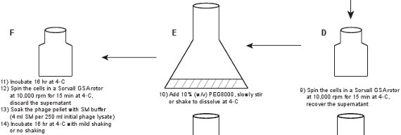
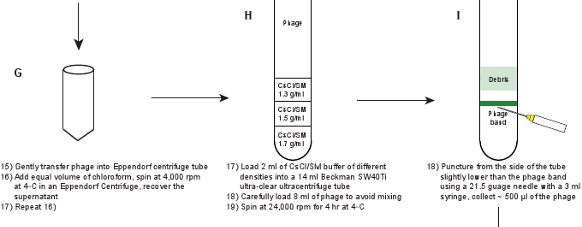

Figure 1. Flow chart describing the creation of fluorescent phages. A crude phage lysate is first obtained by inducing a lysogen of the gpD-EYFP phage, harboring a plasmid expressing wild type gpD protein (panels A-B). The phage is purified through a series of steps (panels C-L).
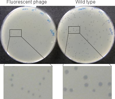
Figure 2. Phage plaques. Plaques of the fluorescent phage (left) are smaller than those of wild type (right) after incubating plates for 12 hr at 37°C.
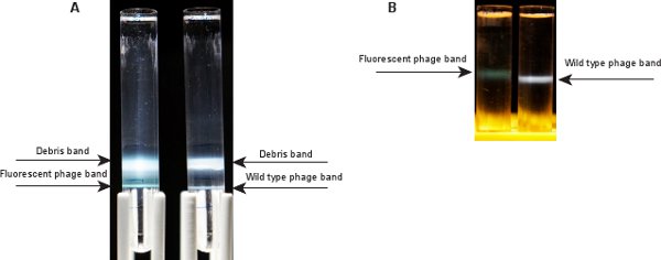
Figure 3. Phage bands after ultracentrifugation. A) Two bands are visible after ultracentrifugation in a CsCl step gradient. The top one corresponds to cell debris and empty phage capsids; the bottom band contains the desired phage. Left: fluorescent phage, right: wild type. B) A single phage band is visible after ultracentrifugation in a CsCl equilibrium gradient. The fluorescent phage band (left) is greenish, compared to a bluish band for wild type phage (right).
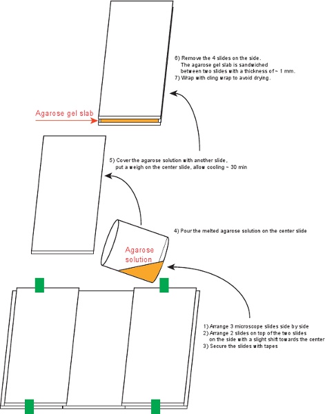
Figure 4. The procedure of preparing agarose gel slabs.
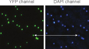
Figure 5. Fluorescent images of phages after DAPI staining. Individual phages are easily distinguishable, and YFP and DAPI signals co-localize very well.

Figure 6. Schematic description of phage infection and imaging setup. Click here to view a full-sized version of this image.
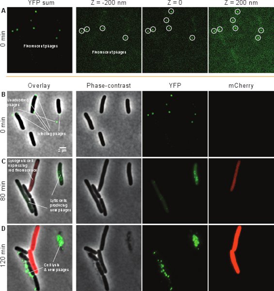
Figure 7. Typical images from a time-lapse movie of phage infection. Shown are the phase-contrast, YFP and mCherry channels, as well as an overlay of the three channels. (A) YFP-channel images from the initial time frame. Left, the sum of YFP images at different z-positions. The three right images are sample YFP images at different z-positions, corresponding to different areas of the cell surface. (B), (C) and (D) Overlaid images (left) of the phase-contrast (middle-left), YFP (middle-right) and mCherry (right) channels at different time frames. (B) At t = 0, two cells are seen, each infected by a single phage (green spots), and one cell is infected by 3 phages. Also observed are some unadsorbed phages. (C) At t = 80 min, the two cells infected by single phages have each gone into the lytic pathway, as indicated by the intracellular production of new phages (green). The cell infected by 3 phages has gone into the lysogenic pathway, as indicated by the production of mCherry from the PRE promoter (red). (D) At t = 2 hr, the lytic pathway has resulted in cell lysis (cell exploded), while the lysogenic cell has divided§.
§Left panels of Figure 7(C) and (D) are reprinted from Cell, 141, Lanying Zeng, Samuel O. Skinner, Chenghang Zong, Jean Sippy, Michael Feiss, and Ido Golding, Decision Making at a Subcellular Level Determines the Outcome of Bacteriophage Infection, 682-691, Copyright (2010), with permission from Elsevier.
| Strain name | Relevant genotype | Source/reference |
| Bacterial strains | ||
| LE392 | supF | John Cronan, University of Illinois |
| Phage strains | ||
| λLZ1 | gpD-EYFP, cI857 Sam7 D-eyfp b::kanR | Zeng et al.5 |
| λLZ2 | gpD-mosaic, same genotype as λLZ1 | Zeng et al.5 |
| Plasmids | ||
| pPRE-mCherry | mCherry under the control of PRE, ampR | Zeng et al.5 |
| pPLate*D | gpD under the control of λ late promoter, ampR | Zeng et al.5 |
Table 1. Bacterial strains, phages and plasmids used in this work.
| Density ρ (g/ml) | CsCl (g) | SM (ml) | Refractive Index η |
| 1.30 | 39 | 86 | 1.3625 |
| 1.50 | 67 | 82 | 1.3815 |
| 1.70 | 95 | 75 | 1.3990 |
Table 3. CsCl solutions prepared in SM buffer (100 ml) for step gradients.
Discussion
Bacterial Strains, Phage and Plasmids:
Strain LE392 is supF. It was chosen to suppress the Sam7 mutation in the phage genome (see Table 1 for details). Thus, induced lysogens will eventually lyse and release phage particles, as will infected cells that have chosen the lytic pathway. Lysogenic cells are grown at 30°C due to the presence of the temperature sensitive cI857 allele in the phage genome. After heat induction, gpD-EYFP and wild type gpD are co-expressed from the genome of λLZ1 and the plasmid pPlate*D respectively. As a result, the capsid of the newly created phage λLZ2 contains a mixture of gpD-EYFP and gpD proteins. This mosaic phage is structurally stable and sufficiently fluorescent to allow detection of individual phages5. pPRE-mCherry is a reporter plasmid used to detect choice of the lysogenic pathway. The promoter PRE is activated by CII during the establishment of lysogeny1,11. pPRE-mCherry5 was derived from pE-gfp11 by replacing gfp with mCherry12. For more details see our earlier work5.
Growth Condition Parameters:
During lysogen induction (Section 1), mild shaking at 180 rpm gives a good virus yield13. Use of glucose in the growth medium should be avoided as glucose metabolism generates acidic metabolic products, and mature lambda particles are unstable at acidic pH13. The addition of MgSO4 is aimed at stabilizing the phage capsid3. For phages carrying wild type cI (instead of cI857), the lysogen can be induced using the DNA-damaging agent Mitomycin C3. In Step 1.3, the incubation at 37°C should normally not exceed 90 minutes. It is useful to check the cell density by OD600 every 30 min. For a good lysate, OD600 drops to around 0.2 or less, and the remaining OD600 is a result of cell debris. Incubating too long may result in a lower phage yield since the newly created phage may start to inject their DNA into cell debris. To obtain a visible phage band (at least 1 x 10¹¹ phage particles) in Steps 2.11 and 2.13, grow at least 500 ml culture in Step 1.2. The addition of 0.2% Maltose into the growth medium in Steps 5.1 and 5.2 is aimed at inducing expression of LamB, the receptor for phage lambda adsorption3,14. The 1000-fold dilution instead of 100-fold in Step 5.2 is aimed at reducing the mCherry background level from the reporter plasmid pPRE-mCherry. In Step 5.5 for phage DNA injection triggering, 35°C is chosen to avoid induction of the temperature-sensitive cI857 allele.
Phage Purification:
The phage purification steps (Steps 2.1 through 2.11) can be replaced with other purification protocols5, but the final ultracentrifugation through CsCl equilibrium gradient (Steps 2.12 and 2.13) is unavoidable. Swinging bucket rotors are needed in Steps 2.10 and 2.12 to ensure sharp visible phage bands. Obtaining a pure phage stock can easily take up to a week, so it is necessary to check the phage titer along the way to make sure nothing goes wrong during the intermediate steps.
Phage Handling:
During all purification procedures in Section 2, it is critical to handle phage lysate gently to avoid shearing phage tails from phage heads. During cell infection in Section 5 (e.g., Steps 5.5 through 5.7), it is also critical to avoid the shearing of phage particles from the infected cell. Note that if the phage is sheared from the infected cell after injecting its DNA, the result is a "dark" infection, i.e. the infection outcome will be observed in experiment but the infecting phage will not. To minimize such problems, we use a wide pipette tip whenever handling phages or the phage/cell mixture.
DAPI Testing:
Staining the phage stock with DAPI (Section 4) is a quick and efficient method to check the purity of the phage stock. It can also be used to test for possible degradation of an existing phage stock over time. For a pure stock, the co-localization of YFP and DAPI signals under the fluorescence microscope should be close to 100%. We typically observe that less than 1% of the YFP spots do not contain DAPI (representing capsids without the viral genome), which indicates that these particles did not successfully package the viral DNA or had already injected their DNA elsewhere. Less than 1% of the DAPI spots do not contain YFP (corresponding to non-fluorescent phages). If this is not the case, Steps 2.12 through 2.14 need to be repeated in order to purify again. With regards to imaging parameters, the microscope setup in Step 4.3 is not as critical as in Section 5 because no long-term live-cell imaging is required here. However, keeping the same microscopy settings as in Section 5 is useful if one wishes to calibrate the fluorescence intensity of a single phage particle. If the PBS-agarose slab is not very clean, or too much DAPI dye is used, some DAPI spots corresponding to phage DNA may be surrounded with a "halo". If too little DAPI dye is used, the signal from the DAPI channel may be very weak.
Microscope System:
For the imaging in Section 6, we use a commercial inverted epifluorescence microscope (Eclipse TE2000-E, Nikon) with a 100x objective (Plan Fluo, numerical aperture 1.40, oil immersion) and standard filter sets (Nikon). The fluorescence light source is an Arc lamp with control of light intensity. The following features are computer controlled: x, y and z position; bright field and fluorescence shutters; and fluorescence filter choice. An auto-focus feature is required. Otherwise, the focus may easily drift away during the time-lapse movie (normally 4 hours long). The ability to acquire multiple (x,y) positions at each time point is useful, as it allows to follow multiple infection events in parallel. We typically acquire 8 stage positions in each movie, following up to 100 infection events. The camera we use is a cooled 512x512 CCD with 16x16 μm pixel camera with a dynamic range of 16 bits (Cascade512, Photometrics). Acquisition is performed using MetaMorph software (Molecular Devices). The microscope should be placed in a temperature-controlled room; alternatively, the microscope stage should be surrounded by a temperature-controlled chamber.
Image Acquisition:
For live-cell imaging, it is critical to avoid unnecessary exposure of the sample, which could lead to bleaching and phototoxicity. Therefore, it is best to first characterize your system to find an optimal light exposure which allows for fluorescence detection while not leading to excessive bleaching or inhibiting cell growth. To obtain a good fluorescence image, play with the exciting light intensity, exposure time and camera gain. In Steps 6.2-6.3, the 10 min frame interval is chosen for the purpose of minimizing light exposure. In each frame, only a single in-focus image is needed in phase-contrast (for cell recognition) and fluorescent channels (for determining cell fate). In the first time point, however, multiple z-position images through the YFP channel are required to capture all infecting phages on the cell surface. The YFP exposure time in the initial frame may also need to be higher than that used for the time-lapse movie in the later time frames.
Image Analysis:
Very carefully count phage particles around the cell surface in Step 7.1. As noted above, we take a series of z-stacks through YFP channel in Step 6.2. However, this may still leave some fluorescent phage particles out-of-focus, which challenges the counting. The cell length in the initial time frame is measured using the Metamorph software. The cell length can also be measured by ImageJ or other software tools. Additionally, an automated home built Matlab program can be very useful in obtaining information such as fluorescence change over time along cell lineages.
Acknowledgements
We are grateful to Michael Feiss and Jean Sippy for the guidance on phage creation and purification. We thank Michael Elowitz for providing the cell recognition software, Schnitzcell. Work in the Golding lab is supported by grants from the National Institutes of Health (R01GM082837), the National Science Foundation (082265, PFC: Center for the Physics of Living Cells), the Welch Foundation (Grant Q-1759) and Human Frontier Science Program (RGY 70/2008).
Materials
| Name | Company | Catalog Number | Comments |
| Name of the reagent | Company | Catalogue number | |
| Chloroform | Fisher Scientific | C298-500 | |
| NaCl | Fisher Scientific | S271-3 | |
| DNase I | Sigma | D4527-10KU | |
| RNase | Sigma | R4642-10MG | |
| PEG8000 | Fisher Scientific | BP233-1 | |
| SM buffer | Teknova | S0249 | |
| NZYM | Teknova | N2062 | |
| CsCl | Sigma | C3011-250G | |
| Syringe | Becton Dickinson | 309585 | |
| Needle | Becton Dickinson | 305176 | |
| Dialysis cassette | Thermo Scientific | 66333 | |
| Microscope slide | Corning | 2947-75x50 | |
| Agarose | Fisher Scientific | BP160-100 | |
| SW40Ti ultra-clear tube | Beckman Coulter | 344060 | |
| SW60Ti ultra-clear tube | Beckman Coulter | 344062 | |
| SW40Ti rotor | Beckman Coulter | 331302 | |
| SW60Ti rotor | Beckman Coulter | 335649 | |
| Refractometer | Fisher Scientific | 13-947 | |
| Epifluorescence microscope | Nikon | Eclipse TE2000-E |
Table 2. Reagents and equipment.
References
- Oppenheim, A. B., Kobiler, O., Stavans, J., Court, D. L., Adhya, S. Switches in bacteriophage lambda development. Annu. Rev. Genet. 39, 409-429 (2005).
- Ptashne, M. . A genetic switch : phage lambda revisited. , (2004).
- Hendrix, R. W. . Lambda II. , (1983).
- Hershey, A. D. . The Bacteriophage lambda. , (1971).
- Zeng, L. Decision making at a subcellular level determines the outcome of bacteriophage infection. Cell. 141, 682-691 (2010).
- Edgar, R. Bacteriophage infection is targeted to cellular poles. Mol. Microbiol. , (2008).
- Ausubel, F. M. . Current protocols in molecular biology. , (1994).
- Sambrook, J., Russell, D. W. . Molecular cloning : a laboratory manual. , (2001).
- Fasman, G. D. . Practical handbook of biochemistry and molecular biology. , (1989).
- Kaiser, A. D. On the internal structure of bacteriophage lambda. J. Gen. Physiol. 49, 171-178 (1966).
- Kobiler, O. Quantitative kinetic analysis of the bacteriophage lambda genetic network. Proc Natl Acad Sci. 102, 4470-4475 (2005).
- Shaner, N. C. Improved monomeric red, orange and yellow fluorescent proteins derived from Discosoma sp. red fluorescent protein. Nat. Biotechnol. 22, 1567-1572 (2004).
- Zeng, L. . Personal communication with M. Feiss. , .
- Schwartz, M. The adsorption of coliphage lambda to its host: effect of variations in the surface density of receptor and in phage-receptor affinity. J. Mol. Biol. 103, 521-536 (1976).
Explore More Articles
This article has been published
Video Coming Soon
ABOUT JoVE
Copyright © 2024 MyJoVE Corporation. All rights reserved