Micro 3D Printing Using a Digital Projector and its Application in the Study of Soft Materials Mechanics
In This Article
Summary
We demonstrate controlled pattern transformation of swelling gel tubes by elastic instability. A simple projection micro stereo-lithography setup is built using an off-the-shelf digital data projector to fabricate three-dimensional polymeric structures in a layer-by-layer fashion. Swelling hydrogel tubes under mechanical constraint display various circumferential buckling modes depending on dimension.
Abstract
Buckling is a classical topic in mechanics. While buckling has long been studied as one of the major structural failure modes1, it has recently drawn new attention as a unique mechanism for pattern transformation. Nature is full of such examples where a wealth of exotic patterns are formed through mechanical instability2-5. Inspired by this elegant mechanism, many studies have demonstrated creation and transformation of patterns using soft materials such as elastomers and hydrogels6-11. Swelling gels are of particular interest because they can spontaneously trigger mechanical instability to create various patterns without the need of external force6-10. Recently, we have reported demonstration of full control over buckling pattern of micro-scaled tubular gels using projection micro-stereolithography (PμSL), a three-dimensional (3D) manufacturing technology capable of rapidly converting computer generated 3D models into physical objects at high resolution12,13. Here we present a simple method to build up a simplified PμSL system using a commercially available digital data projector to study swelling-induced buckling instability for controlled pattern transformation.
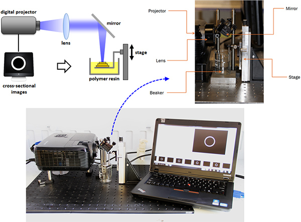
A simple desktop 3D printer is built using an off-the-shelf digital data projector and simple optical components such as a convex lens and a mirror14. Cross-sectional images extracted from a 3D solid model is projected on the photosensitive resin surface in sequence, polymerizing liquid resin into a desired 3D solid structure in a layer-by-layer fashion. Even with this simple configuration and easy process, arbitrary 3D objects can be readily fabricated with sub-100 μm resolution.
This desktop 3D printer holds potential in the study of soft material mechanics by offering a great opportunity to explore various 3D geometries. We use this system to fabricate tubular shaped hydrogel structure with different dimensions. Fixed on the bottom to the substrate, the tubular gel develops inhomogeneous stress during swelling, which gives rise to buckling instability. Various wavy patterns appear along the circumference of the tube when the gel structures undergo buckling. Experiment shows that circumferential buckling of desired mode can be created in a controlled manner. Pattern transformation of three-dimensionally structured tubular gels has significant implication not only in mechanics and material science, but also in many other emerging fields such as tunable matamaterials.
Protocol
1. Preparation of Prepolymer Solution
- Mix poly(ethylene glycol) diacrylate (PEG-DA) (average molecular weight ~575, Sigma-Aldrich) and poly(ethylene glycol) (PEG) (average molecular weight ~200, Sigma-Aldrich) at 1:2 weight ratio.
- Add 0.67 %wt. photo-initiator (Phenylbis(2,4,6-trimethylbenzoyl)phosphine oxide, Sigma-Aldrich). The solution should be kept in dark environment from this point on.
- Add 0.05 %wt. photo-absorber (Sudan I, Sigma-Aldrich).
- Mix the solution for 24 hr at room temperature using a magnetic stirrer.
2. Setting Up a Desktop 3D Printer Using a Digital Data Projector
- Place a digital data projector on a flat and stable position, and connect it to a computer with Microsoft PowerPoint installed.
- Place a convex lens right in front of the beam output lens of the digital projector. Choose a convex lens to make the focal plane about 10 cm away from the projector. (Optical resolution becomes smaller for a lens with shorter focal length, but one needs to reserve some space for optical components.)
- Place a mirror after the convex lens on the beam path at 45° angle to direct the beam straight down.
- Place a sample holder at the focal plane of the projected beam. The sample holder should be attached to a linear stage by which the vertical position of the sample holder is controlled.
- Place a resin bath underneath the sample holder.
3. Design and Fabrication of Gel Tubes
- Determine diameter, wall thickness, and height of the gel tube to be fabricated.
- Draw cross-sectional images for the gel tube. The images should be in white with black background. Insert these image in Microsoft PowerPoint slides.
- Start slideshow in Microsoft PowerPoint and project any image. Place the sample holder at the focal plane by adjusting the vertical position using attached stage.
- Switch to a "dummy" black image so that there will be no unwanted polymerization while putting prepolymer solution.
- Pour prepolymer solution to resin bath. Fill the bath until the solution slightly covers the sample holder. Now it is ready for print 3D object.
- Switch to the slide containing the first cross-sectional image of the gel tube to polymerize the first layer. Keep projecting the image for 8 sec and switch back to "blackout" slide.
- Rotate the knob on the linear stage by ¼ turn (~160 μm) to lower the sample holder. Now fresh resin flows in to cover the polymerized first layer.
- Project the cross-sectional image again to polymerize the second layer on top of the proceeding one. Repeat steps 3.6-3.8 until the gel tube of the desired height is fabricated.
- Once all layers are complete, lift the sample holder out of the prepolymer solution, and retrieve the fabricated sample carefully using a razor blade.
- Rinse the sample in acetone for ~3 hr, and then allow it to dry for ~1 hr.
4. Swelling Experiment for Prescribed Pattern Formation by Elastic Instability
- Prepare water-oil dual layer liquid in a transparent glass dish.
- Attach the dry sample on a sample holder using super glue.
- Flip the sample holder so that the sample is upside down. Immerse the sample in the water-oil liquid bath. Approach the sample to water-oil interface from the oil layer. The sample begins to swell when the sample touches the water surface while the base substrate part on which the gel tube was fixed stayed in the top oil layer. In this way, water can diffuse into the tube wall allowing the sample swell before the constraining base relaxes by wetting. Monitor the pattern change as the gel tube swells using a digital camera.
Representative Results
A simple PμSL system using an off-the-shelf digital data projector is shown in Figure 1. A convex lens with a focal length of 75 mm concentrates the beam into small illumination area of 2 cm by 2 cm. Resulting in-plane optical resolution is about 45 μm. Vertical resolution is determined by the precision level of the linear stage. Layer thickness of the structures made for this study is 160 μm. Each layer was polymerized for 8 sec light illumination. A representative 3D structure fabricated by the system is shown in Figure 1D. This objects consists of 58 layers of PEGDA.
We prepared photo-curable PEGDA hydrogel. Low crosslinking, therefore large swelling, of PEGDA hydrogel was achieved by adding non-crosslinking PEG into prepolymer solution. Length-wise swelling ratio of the resulting PEGDA hydrogel is 1.5, which corresponds to higher than 300% volumetric expansion.
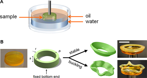
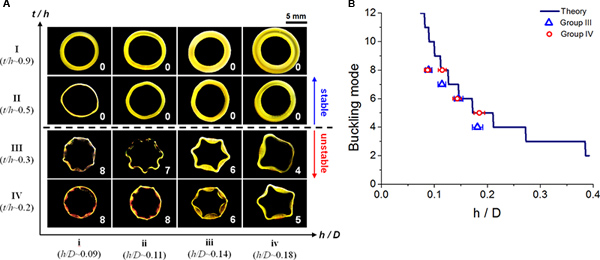
A set of PEGDA hydrogel tubes were designed and fabricated based on our theory12. We placed a sample upside down and put in the bath with water covered with oil layer on top as illustrated in Figure 2A. Depending on the dimensional parameters, circular tubes either remained stable or transformed into a wavy pattern as shown in Figure 2B. The wide variety of swelling pattern of different samples was captured by a digital camera and presented in Figure 3A.

Figure 1. A desktop projection micro-stereolithography system (a) schematic representation (b) actual system (c) close-up view of components (d) representative 3D structures. Click here to view larger figure.

Figure 2. (a) Experimental setup for hydrogel tube swelling (b) constrained hydrogel tube transforms into different patterns. Scale bar indicates 5 mm.

Figure 3. (a) Patterns formed in swelling experiment. Vertical axis indicates t/h (thus stability), and horizontal axis indicates h/D (thus buckling mode). Scale bar indicates 5 mm. (b) Buckling mode depends only on h/D. Experimental result agrees well with theoretical prediction. Click here to view larger figure.
| Sample | D (μm) | t (μm) | h (μm) | |
| I | i | 9300 ± 420 | 760 ± 40 | 840 ± 40 |
| ii | 9700 ± 420 | 1040 ± 40 | 1060 ± 40 | |
| iii | 9700 ± 420 | 1210 ± 40 | 1340 ± 40 | |
| iv | 9700 ± 420 | 1660 ± 40 | 1680 ± 40 | |
| II | i | 9000 ± 420 | 480 ± 40 | 880 ± 40 |
| ii | 9000 ± 420 | 660 ± 40 | 1060 ± 40 | |
| iii | 9500 ± 420 | 740 ± 40 | 1350 ± 40 | |
| iv | 9200 ± 420 | 970 ± 40 | 1650 ± 40 | |
| III | i | 8900 ± 420 | 160 ± 40 | 790 ± 40 |
| ii | 8900 ± 420 | 300 ± 40 | 1020 ± 40 | |
| iii | 9100 ± 420 | 380 ± 40 | 1330 ± 40 | |
| iv | 9000 ± 420 | 490 ± 40 | 1630 ± 40 | |
| IV | i | 8900 ± 420 | 140 ± 40 | 780 ± 40 |
| ii | 8800 ± 420 | 190 ± 40 | 1010 ± 40 | |
| iii | 9300 ± 420 | 230 ± 40 | 1340 ± 40 | |
| iv | 8900 ± 420 | 290 ± 40 | 1650 ± 40 | |
Table 1. Sample dimensions measured through optical microscope. Errors indicate measurement uncertainty.
Discussion
In swelling of tubular hydrogel constrained on the substrate, stability depends only on t/h and buckling mode depends only on h/D12. Four groups of samples (I-IV) with different levels of normalized thickness t/h were fabricated, with group I being thicker and group IV being more slender. Each group consists of four samples (i-iv) with different levels of normalized height h/D, with the sample i being shorter and the sample iv being taller. Dimensions of the fabricated samples are presented in Table 1. Group I and II are designed to stay stable during swelling, whereas group III and IV are designed to buckle and transform upon swelling. For buckling samples, buckling mode should decrease with sample height. Figure 3A shows experimental result. As theory predicts, samples in group I and II were stable and remained circular on swelling, while samples in group III and IV all went through elastic instability and buckled. Also, samples with the same h/D displayed similar buckling mode. Figure 3B compares experimentally observed buckling modes of samples in group III and IV with theoretical prediction. We can see that samples with the same h/D pose the same post-buckling pattern regardless of the thickness and that experimental results agree well with the theory.
We present how to build up a simple desktop 3D printing system using a commercially available digital data projector. The proposed approach relies on photocuring of polymer to construct 3D structures, and therefore, any photocurable polymers can be also used in general, as far as the photoinitiator has appropriate absorbance in visible wavelength range. Note that many commercially available photoinitiators are designed for ultra-violet (UV) wavelengths, but the photoinitiator used here has relatively higher absorbance at wavelengths longer than 400 nm. Offering an easy and rapid way to fabricate 3D objects, this method will find many applications in various fields including soft materials mechanics as demonstrated here.
Acknowledgements
The authors would like to thank Joseph Muskin and Matthew Ragusa at the University of Illinois at Urbana-Champaign for providing cross-sectional images for 3D structures shown in Figure 1D.
Materials
| Name | Company | Catalog Number | Comments |
| Name of the reagent | Company | Catalogue number | Comments (optional) |
| Poly(ethylene glycol) diacrylate | Sigma-Aldrich | 437441 | Mw~575 |
| Poly(ethylene glycol) | Sigma-Aldrich | P3015 | Mw~200 |
| phenylbis(2,4,6-trimethylbenzoyl) phosphine oxide | Sigma-Aldrich | 511447 | Photo-initiator |
| Sudan I | Sigma-Aldrich | 103624 | Photo-absorber |
| Digital data projector | Viewsonic | PJD6221 | |
| Convex lens | Thorlabs | LA1145 | f = 75.0 mm |
| Mirror | 4" silicon wafer | ||
| Manual stage | Velmex | A2506DE-S2.5 |
References
- Timoshenko, S. P., Gere, J. M. . Theory of Elastic Stability. , (1961).
- Sharon, E., Marder, M., Swinney, H. L. Leaves Flowers and Garbage Bags: Making Waves. American Scientist. 92, 254-261 (2004).
- Kücken, M., Newell, A. C. Fingerprint formation. Journal of Theoretical Biology. 235, 71-83 (2005).
- Liang, H., Mahadevan, L. The shape of a long leaf. Proceedings of the National Academy of Sciences. 106, 22049-22054 (2009).
- Bayer, S. A., Altman, J. . The human brain during the second trimester. , (2005).
- Trujillo, V., Kim, J., Hayward, R. C. Creasing instability of surface-attached hydrogels. Soft Matter. 4, 564 (2008).
- Breid, D., Crosby, A. J. Effect of stress state on wrinkle morphology. Soft Matter. 7, 4490 (2011).
- Mora, T., Boudaoud, A. Buckling of swelling gels. The European Physical Journal E. 20, 119-124 (2006).
- DuPont, S. J., Cates, R. S., Stroot, P. G., Toomey, R. Swelling-induced instabilities in microscale, surface-confined poly(N-isopropylacryamide) hydrogels. Soft Matter. 6, 3876-3882 (2010).
- Dervaux, J., Couder, Y., Guedeau-Boudeville, M. -. A., Ben Amar, M. Shape Transition in Artificial Tumors: From Smooth Buckles to Singular Creases. Physical Review Letters. 107, 018103 (2011).
- Jang, J. -. H., Koh, C. Y., Bertoldi, K., Boyce, M. C., Thomas, E. L. Combining Pattern Instability and Shape-Memory Hysteresis for Phononic Switching. Nano Letters. 9, 2113-2119 (2009).
- Lee, H., Zhang, J., Jiang, H., Fang, N. X. Prescribed Pattern Transformation in Swelling Gel Tubes by Elastic Instability. Physical Review Letters. 108, 214304 (2012).
- Sun, C., Fang, N., Wu, D. M., Zhang, X. Projection micro-stereolithography using digital micro-mirror dynamic mask. Sensors and Actuators A: Physical. 121, 113-120 (2005).
- Muskin, J., Ragusa, M., Gelsthorpe, T. Three-Dimensional Printing Using a Photoinitiated Polymer. Journal of Chemical Education. 87, 512-514 (2010).
This article has been published
Video Coming Soon
ABOUT JoVE
Copyright © 2025 MyJoVE Corporation. All rights reserved