Techniques for Processing Eyes Implanted with a Retinal Prosthesis for Localized Histopathological Analysis: Part 2 Epiretinal Implants with Retinal Tacks
In This Article
Summary
Here we describe histological techniques for visualising ocular tissue directly adjacent to a metal epiretinal tack and retinal prosthesis.
Abstract
Retinal prostheses for the treatment of certain forms of blindness are gaining traction in clinical trials around the world with commercial devices currently entering the market. In order to evaluate the safety of these devices, in preclinical studies, reliable techniques are needed. However, the hard metal components utilised in some retinal implants are not compatible with traditional histological processes, particularly in consideration for the delicate nature of the surrounding tissue. Here we describe techniques for assessing the health of the eye directly adjacent to a retinal implant secured epiretinally with a metal tack.
Retinal prostheses feature electrode arrays in contact with eye tissue. The most commonly used location for implantation is the epiretinal location (posterior chamber of the eye), where the implant is secured to the retina with a metal tack that penetrates all the layers of the eye. Previous methods have not been able to assess the proximal ocular tissue with the tack in situ, due to the inability of traditional histological techniques to cut metal objects. Consequently, it has been difficult to assess localized damage, if present, caused by tack insertion.
Therefore, we developed a technique for visualizing the tissue around a retinal tack and implant. We have modified an established technique, used for processing and visualizing hard bony tissue around a cochlear implant, for the soft delicate tissues of the eye. We orientated and embedded the fixed eye tissue, including the implant and retinal tack, in epoxy resin, to stabilise and protect the structure of the sample. Embedded samples were then ground, polished, stained, and imaged under various magnifications at incremental depths through the sample. This technique allowed the reliable assessment of eye tissue integrity and cytoarchitecture adjacent to the metal tack.
Introduction
Retinitis pigmentosa (RP) is a hereditary disorder that causes widespread loss of photoreceptors, which are the cells in the outermost layer of the retina responsible for transducing light, in the form of photons, into neural activity. Importantly, patients with RP typically have residual neurons in the other layers of their retina which are still functional. Retinal prostheses are capable of restoring some limited vision to these patients by targeting these surviving neurons with electrical stimulation to activate their visual pathway1,2. Perceptual outcomes from clinical trials have shown promising early results and recently some devices have been approved for commercial use. Currently, there are three main anatomical locations in which clinical retinal prostheses have been positioned: epiretinally3,4, subretinally5,6 and suprachoroidally7,8. Different devices utilise different materials and their form is customised to the location in which they are implanted. However, they all create visual percepts by activating the residual neurons of the retina with electrical pulses.
There is the potential for any medical prosthesis to damage surrounding tissue due to mechanical effects of the initial placement or subsequent ongoing forces. In the case of implantable stimulators, such as retinal prostheses, there is the additional consideration that the electrical parameters should be within safe limits. Patient safety is paramount, so devices must be rigorously tested in preclinical studies before advancing to a clinical setting9-15. In our companion article, we described a method for assessing the localized histopathology of the eye surrounding an implant positioned in the suprachoroidal space16. In the present manuscript, we describe a technique for visualising eye tissue surrounding an electrode array tacked to the retina epiretinally, in a preclinical (feline) model (Figure 1).
The epiretinal location is the most commonly utilised position for locating a visual prosthesis. Electrode arrays situated here are typically affixed to the retina with a metal tack that penetrates all the layers of the eye17-20. Prior to the techniques described in the present manuscript, it was difficult to accurately assess the retinal and other tissues immediately surrounding a tack. Standard eye fixation using neutral buffered formalin resulted in artifactual retinal damage due to the differential movement of the retina and sclera against the fixed point of the tack. Therefore any actual damage caused by the tack and epiretinal array could not be accurately observed. In addition, sectioning the eye tissue could not be performed with the retinal tack in situ as metal objects cannot be readily cut with traditional histological apparatus; removing the tack before histological processing was also undesirable as this also led to artifactual retinal damage.
The aim of the present study was twofold: 1) to reduce retinal detachment artefact so that any damage caused by the tack and the epiretinal implant array can be reliably assessed; and 2) to visualise the retinal architecture adjacent to the tack without removing it. In order to achieve aim 1, a new fixation technique was utilised (as described in the companion article16), which reduces artifactual retinal delamination. In order to achieve aim 2, we modified an embedding, grinding, and polishing technique, originally developed for in situ observation of cochlear implant electrodes21-23. The methods described in this manuscript allow the visualisation of the retina surrounding and adjacent to a tack in situ while minimizing artifactual retinal damage and therefore allowing accurate assessment of any potential damage caused by the tack and epiretinal array.
Protocol
NOTE: All procedures were approved by The Royal Victorian Eye and Ear Hospital’s Animal Research & Ethics Committee (RVEEH AEC; #10-199AB). The subjects were treated according to the National Health and Medical Research Council’s “Australian Code of Practice for the Care and Use of Animals for Scientific Purposes” (2013) and the “Prevention of Cruelty to Animals Act” (1986; and amendments). All surgical, clinical assessment and electrophysiological procedures were carried out under anaesthesia and all efforts were made to minimize suffering.
1. Enucleation and Fixation
NOTE: Follow the enucleation and fixation procedure described in detail in the companion manuscript16, taking extra care around device cables or vitrectomy ports, if present. Briefly, this involves:
- Transcardially perfuse the subject with warm saline followed by cold neutral buffered formalin.
- Tie sutures to the eyeball to serve as landmarks.
- Enucleate the eye16, maintaining the device cables and any attachment patches/tabs.
- Post-fix the eye in Davidson’s solution for 18 - 36 hr.
- Transfer to 50% ethanol for 6 - 8 hr.
- Transfer to 70% ethanol and refrigerate (4 °C) until dissection.
2. Electrode Removal and Dissection.
NOTE: Not all epiretinal implants will have the same form factor, but in general there will be an electrode array and some form of flexible and conformable carrier material. Devices that are tacked to the retina feature a tack hole where the metal tack penetrates the array and the back of the eye, keeping these together.
- Visualise the implant and the point where it is secured to the retina.
- Using a 15 degree blade make a circumferential trans-corneal incision and remove the corneal cap to expose the underlying iris and lens.
- Using a 15 degree blade, disinsert the zonular fibres of the lens and remove the lens in toto, exposing the posterior chamber with the epiretinal implant and the metal tack in situ.
- Depending on the implant and the study being performed, remove extraneous components before further dissection.
NOTE: In the present example, the epiretinal array being evaluated consisted of a prototype hermetic diamond electrode and electronics package housed within a conformal silicone carrier (produced in house; refer to 20).- Here, carefully extract the diamond electrode package by fine dissection with a scalpel. Leave the silicone body of the implant along with the retinal tack and the remnants of the platinum wiring (Figure 2). If an embedded array/housing is not part of the device design under investigation, then omit this step (2.2).
- Carefully dissect a sample that includes the tack and surrounding tissue in the desired orientation. Use fine dissection scissors to cut full thickness strips from the back of the eye, including sclera, choroid and retina. Take a sample, which gives a longitudinal cross section of the tack, showing all the retinal layers adjacent to the tack (Figure 2)
NOTE: The desired orientation for the sample may differ depending on the particular result desired. For example, if one wishes to examine the proximity of the tack damage to the optic disk then the optic disk should be included within the sample.
3. Dehydration, Embedding, Mounting, Grinding, Staining, and Imaging
- Dehydrate the sample over three days in progressive ethanol stages:
- Dehydrate the sample in 70% ethanol for 2 hr twice.
- Dehydrate the sample in 80% ethanol for 2 hr twice and then O/N.
- Dehydrate the sample in 90% ethanol for 2 hr twice.
- Dehydrate the sample in 100% ethanol for 2 hr twice and then O/N.
- Dehydrate the sample in 100% acetone for 2 hr twice.
- Remove the sample from the acetone and observe it under a light microscope as it air-dries at RT. Transfer the sample to epoxy (refer to step 3.4) just before it starts to curl/collapse.
NOTE: Removing liquid from the soft tissues results in collapsed cells and shrinkage. An appreciation of when the tissue curling/collapse occurs is developed with experience.
- Remove the sample from the acetone and observe it under a light microscope as it air-dries at RT. Transfer the sample to epoxy (refer to step 3.4) just before it starts to curl/collapse.
- Prepare medical grade epoxy resin according to manufacturer’s directions. To cure the resin, use either 55 °C for 1 hr or 24 hr at RT. Place in a vacuum chamber for ~ 5 min at ~ 50 mbar for removal of air bubbles. Regulate the vacuum manually as an excessive vacuum will cause the epoxy mixture to boil and degassing will not occur effectively
NOTE: Perform step 3.3 concurrently with step 3.2. - Embed the sample in clear epoxy resin. Immerse the eye tissue in degassed epoxy in an appropriate sealable container and leave O/N at RT to cure.
- Take care to embed the sample in the desired orientation (Figure 2) by resizing and re-embedding the cured epoxy block. Re-embed the resized block containing the eye tissue such that the long axis of the tack is oriented parallel to the bottom of the mould (yellow cup - Figure 3A).
- Mount the resin in a grinding specimen holder and grind the sample (230 - 250 rpm with water on, manual grinding) using silicon carbide paper (starting with 800 grid; Figures 3C and 3E).
- For staining, dip the ground surface in toluidine blue stain for 3 - 5 min, or until stain develops (Figure 3F).
- Rinse with tap water (Figure 3G).
- Image the ground surface of the specimen with a high power dissection scope to visualize the cellular layers of the retina (Figure 3H). Apply a drop of distilled water on the top surface of the epoxy above the specimen to smooth the diffraction at the air-epoxy interface. Use an optical fibre ‘gooseneck’ light source to illuminate the sample.
- Repeat steps 3.6 – 3.9, each time grinding away a pre-set thickness of sample (minimum precise and reproducible grinding increment of specimen holder is 20 μm).
Representative Results
The fixation protocol substantially reduced artifactual detachment and delamination of the retina16. Orientation of the specimen within the epoxy block was achieved consistently using the described two-step embedding process. The incremental grinding procedure required a moderate level of manual dexterity to achieve optimum results, but was aided by the adjustable specimen holder which provided fine control over the increment resolution. In all cases (n = 5) the tack was located and ground/polished with desirable and consistent results. The retinae adjacent to the tacks were resolvable and stained appropriately. Polishing the surface of the epoxy resin block with a grade P#800 silicon carbide paper was sufficient to image the cellular macrostructure of the embedded tissue. Higher grade paper, or diamond slurry may be used to further polish the surface at any given depth if desired. A dissection microscope and optical fiber ‘gooseneck’ light source was found to be suitable for imaging the surface of the ground block and the embedded tissue sample. The position of the light source was varied by trial and error to find a location and angle that gave the best illumination and contrast through the microscope. Adding a drop of distilled water to the surface of the block, above the sample, was useful to reduce light path diffraction and/or smooth distortions at the epoxy air interface. Figure 4 shows example images of retinal tissue visualised immediately adjacent to a titanium retinal tack using this technique. Non-artifactual retinal detachment and folding can be seen on either side of the silicone (Figure 4A). The tack shaft is visible embedded in silicone; the head of the tack has penetrated the retina and sclera. There is non-artifactual retinal detachment in the unstained retina either side of the silicone (Figure 4C). The technique has shown that, in this instance, there is retinal disorganisation adjacent to the tack and compression of the retina at one side due to an oblique insertion angle. Note that the images presented are merely illustrations of the success of the technique, not representative of tack-damage histopathology in general.

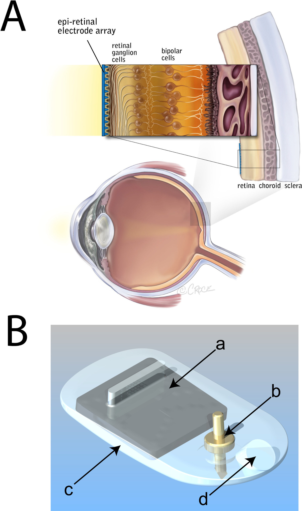
Figure 1. Placement of an epiretinal electrode array. (A) Schematic diagram of the eye showing a magnified cross-section of the posterior sclera, choroid and degenerate retina (lacking photoreceptors). An electrode array is depicted in blue, affixed epiretinally. (B) Computer-aided-drawing of an epiretinal electrode array. a, integrated-circuit (‘chip’) and electrode package; b, titanium retinal tack; c, medical grade silicone housing; d, lead exit point. Panel A modified from an original illustration provided courtesy of Bionic Vision Australia, copyright Beth Croce. Please click here to view a larger version of this figure.

Figure 2. Electrode removal and dissection of the eye. High dynamic range macro photographs of an enucleated feline eye with epiretinal tack in situ. (A) Post fixation with Davidson’s fixative to preserve retinal architecture16, the enucleated eye was dissected. The electrode array package was removed from the silicone carrier (dashed square outline indicates original location of electrode array) with the tack (arrow) and silicone body of the implant remaining. (B) The eye was dissected with the longitudinal cross section adjacent to the tack (dashed line). The tack remains embedded in the posterior wall of the eyecup (arrow), stabilised predominantly by the sclera. The tissue section containing the tack was prepared for resin embedding and grinding (right segment), while the section containing the retina beneath the removed electrode array was prepared for standard histological processing16 (left segment). A ruler with 0.5 mm increments is shown at the bottom edge of each panel. Please click here to view a larger version of this figure.

Figure 3. Epoxy embedment and grinding of the tack and retinal tissue. Photographs of the epoxy embedded and aligned tissue sample, grinding, staining and imaging of the tack and retinal tissue. (A) The tack sample was embedded in an epoxy resin block. Using the mould, the sample was oriented so the longitudinal plane is parallel to the bottom of the mould. (B) The cured epoxy block containing the tack sample. (C) The epoxy block was mounted in a grinding specimen holder, ready for grinding. (D) The sample was orientated so imaged sections of the ground tissue contain the retinal cellular layers and longitudinal axis of the tack. (E) The sample was ground using silicon carbide paper on a rotary grinder. (F) The ground surface of the block was stained with toluidine blue to identify the retinal layers. (G) The block was rinsed in tap water to remove excess stain. (H) The toluidine blue stained retinal layers and tack were imaged using a high powered dissection scope.

Figure 4. High and low power images of the tack and retina. At various points during the grinding process images were taken with a dissecting scope, showing longitudinal sections of the tack (asterisk) penetrating through the eye and exiting the sclera (‘S’), adjoining silicone (hash) and toluidine blue stained and unstained retina (‘R’). Note these are example images only to demonstrate the present visualisation technique, and are not representative of all epiretinal implant or tack insertion histology results. Ground remnants of the platinum wiring are visible in panels A-D (‘W’). (A) Low power, unstained image of the tack penetrating the retina and sclera. (B) High powered image of the retinal detachment and folding in unstained retina adjacent to the silicone carrier in image A. (C) Low power image at the centre of the tack shaft. (D) High power image of the centre of the tack in image C. (E) In a separate sample, with no silicone carrier, a high powered image of toluidine blue stained retina beneath the tack hilt is shown, immediately prior to grinding the tack shaft. (F) Normal toluidine blue stained retinal architecture (GCL: retinal ganglion cell layer; INL: inner nuclear layer; ONL: outer nuclear layer; PR: photoreceptors; T: feline tapetum lucidum) visualised using the same grinding technique. Scale bars in each panel are: A and C = 2 mm; B and D = 500 µm; E = 200 µm; F = 100 µm.
Discussion
Standard histological techniques are unable to process hard metal implants in situ due to limitations in cutting these objects with metal, glass or even diamond blades. In our companion paper16, we showed that the use of a modified whole-eye fixation technique could reduce artifactual retinal delamination. In the current manuscript, an established grinding and polishing technique for visualising cochlear implants21-23in situ was modified for retinal prostheses. A titanium tack, used to secure an electrode array to the retina, epiretinally, was embedded in epoxy along with the surrounding eye tissue. This resin block was then oriented appropriately and progressively ground/polished in order to reveal the tissue morphology immediately adjacent to the metal tack. Images of the polished surface of the block at various depths were taken with a powerful dissection microscope. This technique is useful for: visualising and evaluating the tissue response adjacent to the epiretinal implant; to assess the surgical trauma associated with implantation of the implant; to determine the biological reaction to the hard metal components; and to measure the distance between the implant and the surface of the retina.
This technique will be useful in future safety studies for in situ visualisation of the region adjacent to a retinal tack or other hard (e.g., metallic) objects in the eye. This has direct application in assessing the preclinical safety of prostheses tacked to the retina epiretinally. It may also be useful for evaluating tissue damage in retinal regions in contact with implants located in the sub-retinal location.
There are several ways to verify that the technique has been performed correctly. At each stage, the retina should remain attached to the outer layers of the eye. If there is gross artifactual retinal detachment, this may indicate a problem with the fixation. When the sample is embedded and re-orientated in the final resin block the retina should be close to orthogonal with the grinding-face of the block; this will minimize oblique cutting. It is useful to check that the number of incremental grinding steps (of known step size) required to traverse an object (such as a retinal tack) correlate accordingly with the dimensions of the object.
The technique can be optimised in several ways. Scratches on the surface of the epoxy block associated with the grinding process can be reduced with progressively finer grade polishing. For the present study, we used 800, 1000, 1200, 2400, and 4000 grade silicon carbide paper. Diamond paste could also be used to improve the surface finish. A finer surface finish gives a higher quality image but at the cost of additional polishing time. Another critical consideration for improving the outcome of this technique is the choice and quality of the optics and lighting used for the image capture. Other basic histological stains – particularly Nissl stains, can be used in place of toluidine blue, but may require further optimisation. Some stains will stain the resin as well as the tissue (e.g., Eosin), therefore a shallow polish may be required after the staining to remove background discolouration. Specialised stains, fluorescent dyes and immunohistochemical staining was not attempted, but unless a very specific result is desired, the time required to perform these stains at each grinding level is likely to be prohibitive. However, it may be possible to stain the tissue as a whole before the embedding step (step 3.4)24.
The main limitation of this technique is that once the region of interest has been ground away, it cannot be retrieved, therefore, it is prudent to capture many (possibly redundant) images at a variety of magnifications at each stage of grinding and polishing. It is also important to use small increments for each grinding depth adjustment. Another limitation of this technique is that of the optical magnification and resolution compared with tissue mounted on a glass slide and viewed with a standard (transmission) light microscope. For the purposes of prototyping and assessing the safety of a novel implant device, the gross pathological evaluation is of primary interest. This technique provides an efficient method for observing clinically relevant damage associated with a retinal tack. With practice, the overall time required to gather grind, polish and photograph a given specimen (once embedded) is comparable to the time it would take to section a paraffin block or frozen section.
There is also the potential for the present techniques to be extended to applications outside the scope of retinal implants. This technique is suited for evaluating the tissue adjacent to a hard implant, where implant extraction is not feasible or would damage the interface. For example, this technique could be expanded to evaluate implants made from metal (e.g., platinum, nitinol, etc.) that cannot be cut with conventional histological techniques, such as some deep brain or peripheral nerve electrodes, cannulae for drug delivery, vascular stents or orthopaedic prostheses.
Disclosures
Authors have nothing to disclose. Irfan Durmo is an employee of Cochlear Ltd.
Acknowledgements
Nicole Vella (Macquarie University) for providing reagents; Alexia Saunder (Bionics Institute; BI), Michelle McPhedran (BI), Chris Williams (BI) for experimental support; the Royal Victorian Eye and Ear Hospital (RVEEH) Biological Research Centre staff for animal care; Sue Pierce (RVEEH) for veterinary advice; Anthony Burkitt (Bionic Vision Australia; BVA), Tamara Brawn (BVA) and the BVA staff for administrative support.
This research was supported by the Australian Research Council (ARC) through its Special Research Initiative (SRI) in Bionic Vision Science and Technology grant to Bionic Vision Australia (BVA). The Bionics Institute receives Operational Infrastructure Support from the Victorian Government and also acknowledges support from the Bertalli Family Trust and the J T Reid Charitable Trust. The funders had no role in study design, data collection and analysis, decision to publish, or preparation of the manuscript.
The Bionic Vision Australia Consortia authors for this manuscript are (a-z):
Penelope J. Allen, Owen Burns, Kate E. Fox, Kumaravelu Ganesan, David J. Garret, Hamish Meffin, Joel Villalobos, and Jonathan Yeoh.
Materials
| Name | Company | Catalog Number | Comments |
| Name of the reagent / equipment | Company | Catalogue number | Comments (optional) |
| Acetone | Chem-Supply | AA008 | Propanone BHD Medical grade |
| Epo-Tek 301 Epoxy | Epoxy Technology | Part A 1675-54-3 Part B 9046-10-0 | |
| Ethanol 70-75% v/v | Merck PTY LTD | 4.10261 | Alcohol |
| Ethanol | Merck PTY LTD | 90143 | Alcohol |
| Toluidine blue O | Sigma-Aldrich | T3260 | |
| Ethylenediamine Tetraacetic Acid | Sigma-Aldrich | ||
| TegraPol grinding/polishing machine | Struers | TegraPol-25 | |
| AccuStop specimen holder | Struers | Accustop | |
| Light microscope | Leica | MZ16 | |
| Objective lens | Leica | 2.0x Planapo Objective | |
| Digital Microscope Camera | Leica | DFC-420C | |
| Microscope Software | Leica | Application Suite v4.1.0 |
References
- Shepherd, R. K., Shivdasani, M. N., Nayagam, D. A., Williams, C. E., Blamey, P. J. Visual prostheses for the blind. Trends Biotechnol. 31, 562-571 (2013).
- Santos, A., et al. Preservation of the inner retina in retinitis pigmentosa. Arch Ophthalmol. 115, 511-515 (1997).
- Humayun, M. S., et al. Visual perception in a blind subject with a chronic microelectronic retinal prosthesis. Vision Res. 43, 2573-2581 (2003).
- Roessler, G., et al. Angiographic findings folowing tack fixation of a wireless epiretinal retina implant device in blind RP patients. Graefes Arch Clin Exp Ophthalmol. 249, 1281-1286 (2011).
- Chow, A. Y., et al. The artificial silicon retina microchip for the treatment of vision loss from retinitis pigmentosa. Arch Ophthalmol. 122, 460-469 (2004).
- Zrenner, E., et al. Subretinal electronic chips allow blind patients to read letters and combine them to words. Proc Biol Sci. 278, 1489-1497 (2011).
- Fujikado, T., et al. Testing of semichronically implanted retinal prosthesis by suprachoroidal-transretinal stimulation in patients with retinitis pigmentosa. Invest Ophthalmol Vis Sci. 52, 4726-4733 (2011).
- Saunders, A. L., et al. Development of a surgical procedure for implantation of a prototype suprachoroidal retinal prosthesis. Clin Experiment Ophthalmol. , (2013).
- Lee, S. W., et al. Development of microelectrode arrays for artificial retinal implants using liquid crystal polymers. Invest Ophthalmol Vis Sci. 50, 5859-5866 (2009).
- Sakaguchi, H., et al. Transretinal electrical stimulation with a suprachoroidal multichannel electrode in rabbit eyes. Jpn J Ophthalmol. 48, 256-261 (2004).
- Majji, A. B., et al. Long-term histological and electrophysiological results of an inactive epiretinal electrode array implantation in dogs. Invest Ophthalmol Vis Sci. 40, 2073-2081 (1999).
- Walter, P., et al. Successful long-term implantation of electrically inactive epiretinal microelectrode arrays in rabbits. Retina. 19, 546-552 (1999).
- Ray, A., Chan, L., Thomas, B., Weiland, J. D. Effects of prolonged stimulation at the electrode-retina interface. Conf Proc IEEE Eng Med Biol Soc. 1, 1285-1287 (2006).
- Colodetti, L., et al. Pathology of damaging electrical stimulation in the retina. Experimental eye research. 85, 23-33 (2007).
- Nayagam, D. A. X., et al. Chronic Electrical Stimulation with a Suprachoroidal Retinal Prosthesis: A Preclinical Safety and Efficacy Study. PLoS One. 9, e97182 (2014).
- Nayagam, D. A. X., et al. Techniques for Processing Eyes Implanted With a Retinal Prosthesis for Localized Histopathological Analysis. Journal of visualized experiments : JoVE. , e50411 (2013).
- Laube, T., et al. Development of surgical techniques for implantation of a wireless intraocular epiretinal retina implant in Gottingen minipigs. Graefe's Archive For Clinical And Experimental Ophthalmology = Albrecht von Graefes Archiv fur klinische und experimentelle Ophthalmologie. 250, 51-59 (2012).
- Gerding, H., et al. Successful long-term evaluation of intraocular titanium tacks for the mechanical stabilization of posterior segment ocular implants. Mat.-wiss. u. Werkstofftech. 32, 903-912 (2001).
- Seo, J. -. M., et al. Silicon retinal tack for the epiretinal fixation of the polyimide electrode array. Current Applied Physics. 6, 649-653 (2006).
- Hadjinicolaou, A. E., et al. Electrical stimulation of retinal ganglion cells with diamond and the development of an all diamond retinal prosthesis. Biomaterials. 33, 5812-5820 (2012).
- Briggs, R. J., et al. Comparison of round window and cochleostomy approaches with a prototype hearing preservation electrode. Audiol Neurootol. 11, 42-48 (2006).
- Shepherd, R., et al. An improved cochlear implant electrode array for use in experimental studies. Hear Res. 277, 20-27 (2011).
- Tykocinski, M., et al. Comparison of electrode position in the human cochlea using various perimodiolar electrode arrays. Am J Otol. 21, 205-211 (2000).
- Hardie, N. A., MacDonald, G., Rubel, E. W. A new method for imaging and 3D reconstruction of mammalian cochlea by fluorescent confocal microscopy. Brain Res. 1000, 200-210 (2004).
Reprints and Permissions
Request permission to reuse the text or figures of this JoVE article
Request PermissionThis article has been published
Video Coming Soon
ABOUT JoVE
Copyright © 2025 MyJoVE Corporation. All rights reserved