Utilizing 3D Printing Technology to Merge MRI with Histology: A Protocol for Brain Sectioning
In This Article
Summary
The overall goal of this protocol is to accurately align magnetic resonance imaging (MRI) image volumes with histology sections via the creation of customized 3D-printed brain holders and slicer boxes.
Abstract
Magnetic resonance imaging (MRI) allows for the delineation between normal and abnormal tissue on a macroscopic scale, sampling an entire tissue volume three-dimensionally. While MRI is an extremely sensitive tool for detecting tissue abnormalities, association of signal changes with an underlying pathological process is usually not straightforward. In the central nervous system, for example, inflammation, demyelination, axonal damage, gliosis, and neuronal death may all induce similar findings on MRI. As such, interpretation of MRI scans depends on the context, and radiological-histopathological correlation is therefore of the utmost importance. Unfortunately, traditional pathological sectioning of brain tissue is often imprecise and inconsistent, thus complicating the comparison between histology sections and MRI. This article presents novel methodology for accurately sectioning primate brain tissues and thus allowing precise matching between histology and MRI. The detailed protocol described in this article will assist investigators in applying this method, which relies on the creation of 3D printed brain slicers. Slightly modified, it can be easily implemented for brains of other species, including humans.
Introduction
In vivo MRI provides a noninvasive and sensitive measure of tissue integrity at the macroscopic level. Changes in MRI signal intensity seen in vivo are outcome measures in many ongoing clinical trials.1 While the intensity changes seen via MRI can identify areas of abnormality in the context of the whole brain, they are often not sufficiently specific to differentiate pathological processes. This is especially true of dynamic processes involving multiple pathologies. For example, in multiple sclerosis (MS) or its animal model, experimental autoimmune encephalomyelitis (EAE), inflammation, edema, myelin degradation, axonal destruction, gliosis, and neuronal death overlap. 2, 3 To obtain the necessary specificity regarding the underlying pathology, context must be taken into account, together with knowledge of the histology of the MRI-identified abnormal tissues.
However, even in well-controlled animal experiments, matching histology with in vivo MRI is fundamentally challenging for various reasons. First, the difference in dimensional scales between histology sections and MRI is of several orders of magnitude.4 Second, for proper comparison, the orientation of MRI slice plane must match the sectioning plane of the brain tissue when cut. Due to the shape of the brain, it is very difficult to make consistently straight and accurate cuts when the brain is sitting on a flat surface. Third, the large size of the brain relative to a potentially small area of interest (lesion, tumor, etc.) creates a "needle-in-a-haystack" scenario for the pathologist processing the tissue. Fourth, even when the target tissue is found, it is commonly processed in such a way as to render virtually impossible an association with the original MRI data. Finally, traditional pathological sectioning of brain tissue is often imprecise and inconsistent, further complicating the comparison between histology sections and MRI images.
Previous attempts to overcome these challenges relied on the use of deformational algorithms to coregister the data and/or placement of fiducial markers within or around the tissue as a reference.5, 6, 7, 8 The former approach requires complex computational models that are particularly susceptible to complications due to data formatting, imaging artifacts, and changes caused by tissue processing.4 On the other hand, the latter approach introduces the possibility of contaminating or otherwise harming the tissue itself.9
The approach described here improves the transition between modalities through the use of postmortem MRI to bridge the gap between in vivo MRI and histology. Postmortem MRI provides three-dimensional (3D) images of the brain at higher resolution than can be achieved in vivo and furthermore provides the data needed for producing a morphologically accurate model of the brain surface. This digital model can then be used to create a 3D-printed custom holder for the brain. With careful positioning, the brain holder allows for precise, MRI-oriented brain sectioning, reducing the need for complex mathematical algorithms, and enables a focus on specific regions for targeted sampling.
Our laboratory recently introduced new methods for creating custom brain holders and slicers using postmortem MRI and 3D-printing technology for human10 and marmoset brains.4 The two methods allow for a more accurate correlation between MRI and histology in a research setting, and ultimately allow a deeper understanding of the specific pathology underlying MRI abnormalities. Carefully designed experiments, in which the brain is sampled repeatedly over time in vivo, can provide context for interpretation of the pathology, which in turn can add specificity to interpretation of the MRI. Here, we present a modified protocol in a unified framework that can be applied to any brain tissue, whether it derive from nonhuman primates, rodents, or humans. We provide detailed instructions, and a corresponding video, for the marmoset sectioning. Although the overall protocol applies to any type of brain, due to differences in MRI acquisition and tissue size, as well as the challenges encountered when dealing with specific brain types, there are some differences in the approach depending on the type of brain being processed. In this presentation, sections with "human" will denote differences in protocol specific to the human brain.
Protocol
All animal handling and procedures described herein were performed in accordance with a protocol approved by the National Institute of Neurological Disorders and Stroke Animal Care and Use Committee. Brains were collected from common marmosets (Callithrix jacchus) induced to develop EAE.11 Brains were stored in 10% formalin for between 3 weeks and one year after euthanasia by transcardial perfusion of 4% paraformaldehyde.
1. Postmortem MRI Preparation and Acquisition
- Marmoset Brain
- Prepare a workstation with cotton gauze, a 50 ml centrifuge tube, small spatulas, ~30 ml of a fluorinated oil, paraffin, and the marmoset brain.
- Fill the tube with the fluorinated oil and gauze to the 20 ml mark. Compress the gauze to remove air bubbles along the way.
- Gently dry formalin from the surface of the brain with a paper towel. Insert the brain with the frontal pole toward the bottom of the tube. Carefully secure the brain in the tube using more gauze around the sides to fix its position. Refer to supplementary section 11 for a method of creating an MRI brain cradle for setup of additional MRI scans.
- Fill the rest of the tube with gauze and fluorinated oil. Carefully remove air bubbles along the way. Secure the cap and seal the tube with paraffin.
- Mark the cap in line with the interhemispheric fissure. Wrap the tube in a paper towel and insert it into the coil with the mark top-center.
- Acquire 2D spin echo T2. Parameters are given in Table 1.
- Open the 10 anatomical 150 micron T2-weigted acquisitions in Mipav and register to the 6th acquisition.
NOTE: Registration is an optimized automatic registration 3.5D algorithm with 9 degrees of freedom, windowed sinc interpolation, normalized cross correlation cost function, with a Powell's calling Brent's search algorithm. Rotations were sampled from +10° to -10° with coarse rotations incrementing 5 degrees and fine rotations incrementing 1°. Then average the registered images: Utilities, Image calculator-Bulk images, Average.
- Human Brain
- Separate the forebrain from the brainstem using a cut at the level of the midbrain.10 The hemispheres can also be separated with a cut down the midline.
- Position the forebrain in a cylindrical tube with a hemispheric dome at one end and a spout at the other end.
- Fill the tube with a fluorinated oil through the spout. Remove air bubbles using gentle suction for ~30 min through the spout.
- Acquire 3D T1-MPRAGE. Parameters are given in Table 1.
2. Extracting Brain Surface: Mipav 7.2
- Open the MRI in the coronal orientation.
- Select Algorithms, Transformation tools, Transform, Resample. Select User defined size and resample to isotropic voxels: 0.1 x 0.1 x 0.1 mm. Save the resampled MRI as Brain_MRI_Resampled. Human: Resample to isotropic voxels 0.3 x 0.3 x 0.3 mm.
- Select Algorithms, Filters (spatial), Nonlinear noise reduction. Use the default settings, click on OK.
- Select Displays lookup table and click on the dual threshold button. Drag the slider on the graph to cover the whole brain.
- Select Algorithms, Segmentation, Threshold, Threshold using min/max. Enter the value located in the bottom left corner of the intensity graph (just below the scale) into the "Lower limit" box. Select "binary" in for the output image type and uncheck "invert threshold."
- Select Algorithms, Morphological, Fill holes. Check "Process in 2.5D."
- Because this is an MRI of the full brain, there is some empty space between the hindbrain and cortex that needs to be filled. Human brain: skip this step.
- Using line VOI, draw in a connection between the hindbrain and cortex on both sides of the brain at the most lateral point. Continue this through the brain.
- Select VOI, VOI conversion, All to binary mask. Select Utilities, Image calculator. Select OR from the operator dropdown menu and select the brain mask. Select "Promote destination image type"
- Select Algorithms, Morphological, Fill holes. Check "Process in 2.5D"
- Save the binary mask as Brain_Model.nii.
- Select Algorithms, Extract surface (marching cubes). Select mask image, Save as Brain_Model.ply.
3. Selecting Slice Locations: Mipav 7.2
- Identify tissue of interest or starting position. Calculate the intended slab thickness. In marmoset brain, counting 30 MRI slices per section, and 5 MRI slices per blade gap, creates 3 mm sections with .5 mm blade gaps, resulting in ~3.5 mm slabs. Human brain: 20 MRI slices per section, and 4 MRI slices per blade gap, creates 6 mm sections with 1.2 mm blade gaps, resulting in ~7.2 mm slabs.
- At the location of the first blade gap, click on "box VOI" and then draw a box over the brain. Click inside of the box to select it. Copy and paste the contour for each MRI slice corresponding to the blade gap.
- Skip ahead by the number of MRI slices corresponding to the section thickness and copy and paste the contour corresponding to the next blade gap. Repeat this process through the brain.
- Select VOI, VOI Conversion, All to Binary Mask. Save as Blade_Gaps.nii.
- Select Algorithms, Extract Surface (marching cubes), Mask image, Blade_Gaps.ply.
4. Creating MRI Blade Map: Mipav 7.2
- Open the Brain_MRI_Resampled and the Blade_Gaps.nii images.
- With the Blade_Gaps.nii image selected, select Utilities, Image Math. Select Promote image type and Multiply. Enter 10,000 as the value.
- Select Utilities, Image Calculator. Select Add, and then select the Brain_MRI_Resampled image from the image dropdown box. Select Promote destination image type.
- Save this image as Brain_BladeMap.nii.
- By clicking on the Triplanar view, the locations where the brain will be sliced can be seen in three orthogonal views.
5. Importing Brain and Blade Gap Surfaces: Netfabb Professional
- Select Part, Add part. Choose the files Brain_Model.ply and Blade_Gaps.ply
- Select the brain and click on repair mode. In repair mode:
- Click on the shell selection button, and then click on the brain.
- Click on the toggle selection button to select the other meshes. Click on Remove to delete the other meshes.
- Click on Apply Repair, and remove the old part.
- Right click on the brain. Select move. Click on the To origin button. Record the XYZ parameters that appear. These translation parameters are needed to maintain the blade positioning set up in Mipav. Click on Translate. Then close the window. (Do not click translate more than once. It will translate again using the same parameters.)
- Select the Blade_Gaps model. Right click on the part, and select Move. Enter the XYZ values recorded previously in the XYZ parameters boxes. Now click Translate and close the window.
- Select the Brain_Model model and click on Repair mode. In repair mode:
- Click on the shell selection button, and then click on the brain.
- Right click and select Smooth Triangles. Enter 4-5 iterations. Check Prevent volume shrinking. Human brain: 1-2 iterations.
- Right click, select Reduce Triangles. Enter 200000 in the target triangle count and click Execute.
- Click on Automatic repair, Default repair. Then Click on Apply Repair
- Right click, Rename. Rename the smoothed brain as Smoothed_Brain_Model.
- Select Smoothed_Brain_Model. Right click, Export, STL.
6. Editing Brain Contours: Meshmixer
- Import the Smoothed_Brain_Model into Meshmixer.
- Use the sculpting and selection tools to make adjustments to the mesh. Edits include:
- Use Sculpting tools, Robust smooth. Smooth the area corresponding to the line VOIs. Human brain: skip this step.
- Smooth the surface of the cortex that will be face down in the box.
- Smooth away small divots that might have been created in the meshing and editing process.
- Select Analysis, Inspector, Autorepair all.
- Export the Smoothed_Brain_Model as Smoothed_Edited_Brain_Model.
7. Creating the Brain Slicer Box: Netfabb Professional
- Select Part, Add Part. Choose the file Smoothed_Edited_Brain_Model.
- Select Part, Add Part. Then select the STL file Brain Slicer Parts_Marmoset and click open. Human brain: Brain Slicer Parts_Human (Supplemental code files).
- Right click on the part, and select Extended, Shells to parts. Select each part individually and right click to rename them. (Clicking on the eye next to an object hides it or makes it visible.)Rename the big box Main, the small box Sub, and the cutting box Box_Cutout, the Hexagon shape Blade_Holder_Main, the small flat box Microtome Blade, and the half-tube object Cradle. Human brain: no Blade_Holder_Main, Microtome Blade, or Cradle.
- Hide Main, Sub, Blade, Blade_Holder_Main, Microtome Blade, and Cradle and use shift-select to select all six and the Box_Cutout. Only the Box_Cutout and the Smoothed_Edited_Brain_Model should be visible, but the Smoothed_Edited_Brain_Model should not be selected.
- Click and drag the selected parts to adjust the box position relative to the brain.
- Position the brain in the center of the box. Postion the brain deep enough in the box to be tightly gripped, but not too deep to create overhangs that prevent proper placement.
- Once positioned, the brain box contour can be tested for overhangs. Select the Box_Cutout and the Smoothed_Edited_Brain_Model. Select Boolean Operation.
- Click on the Smoothed_Edited_Brain_Model to turn it red.
- Select Boolean Subtraction, and apply the calculations.
- Check the brain box for overhangs that would prevent the brain tissue from being safely placed into the box. If these overhangs are present, adjust the brain so it is less deep within the box. If the brain is at the desired depth and overhangs are present, refer to supplementary section 10 for a solution for removing the overhangs.
- Select the Blade_Gaps model. Right click, select Move. Record the position Z value, then close the window. This will be the position of the most posterior blade gap.
- Select the Blade STL that came from the Brain Slicer Parts. Right click, select Move.
- Select Absolute translation. Enter the Z value from the 7.8. For the X and Y Values, enter the corresponding value from the current position parameter boxes
- Select the Blade STL. Right click, Click Duplicate.
- Check Arrange parts. Enter the total number of blades in the total count. Enter the same number into the Z count box. Enter the slab thickness into the Z gap. Click on Duplicate. If the slab thickness was varied, the blades will need to be positioned individually. Duplicate each new blade from the previous (moving from posterior to anterior) with the z gap equal to the section thickness for that section.
- Position the Microtome Blade parts at exactly the same intervals as the blades in the slicer by repeating step 7.9 and 7.10 for the Microtome Blade. Human brain: skip this step.
- Select Microtome Blade along with the Blade_Holder_Main part and select Boolean Operation.
- Select all the blades in Microtome Blade to highlight them red. Click on Boolean Subtraction, and apply the calculations.
- Select Repair mode. Perform an Extended repair. Select apply the repair, and remove the old part.
- Rename the part Blade Holder. Export the part as STL.
- Shift-select Smoothed_Edited_Brain_Model, all of the Blade models created in the previous step, and the Sub and Main. Click on Boolean operation.
- Make all of the parts except Main red by selecting them and clicking the arrow under the green box to move them to red.
- Select Boolean Subtraction and then select apply calculations.
- Click on repair mode. In repair mode:
- Check the box for overhangs and sharp points. These can be smoothed in Netfabb or Meshmixer.
- Click Automatic repair, Extended repair. Then apply the repair and remove the old part
- Right click on the repaired brain box and rename it Brain Slicer Box. Export as an STL.
8. Printing the Brain Slicer Box on the Ultimaker 2
- Marmoset Brain: Cura
- Import the Brain Slicer Box into Cura.
- Select Rotate and drag the circle to rotate the box so it is flat on the bed.
- Adjust the print settings: 0.1 mm layer resolution, 50% fill density, Raft.
- Select Save Tool Path to SD card. (Print time ~12 h.)
- Import Blade Holder into Cura and rotate it so the slots are on the sides and the hexagon face is in the XZ or YZ plane.
- Duplicate the object.
- Adjust the print settings: 0.2 mm layer resolution, 20% fill density, Brim.
- Select Save Tool Path to SD card. (Print time ~3 h)
- Human Brain: Cura
- Import the Brain Slicer Box into Cura and rotate as in 8.1.2.
- Adjust the print settings: .2 mm layer resolution, 30-35% fill density, Raft.
- Select Save tool path to SD card. (Print time ~70 h for single hemisphere box.)
- On the Ultimaker 2
- Apply a thin layer of glue stick glue to build plate.
- Insert the SD card. Select print and select the part.
9. Cutting the Brain
- Marmoset Brain
- Prepare a workstation with the fixed brain, the brain slicer, two blade holders, microtome blades, 1 ml of fluorinated oil, flat tweezers, protective gloves, and embedding cassettes.
- Place new microtome blades into the slots on the blade holders. Make sure the beveled edge of each blade is facing in the same direction. Wear protective gloves when handling microtome blades.
- Remove the brain from formalin and gently dry it.
- Place the brain into the slicer. A few drops of fluorinated oil can be applied to the brain and slicer to allow for easy positioning. Make sure the brain is firmly in place.
- Position the blade holders with the blades in the corresponding blade slots.
- Push down on the blade holders firmly and apply slow balance pressure to cut through the brain.
- Remove each slab, one at a time, starting from the front of the brain. It helps to remove the microtome blade in front of a slab before removing the slab itself. Pay close attention to the anterior/posterior orientation of each slab.
- Take pictures of the anterior and posterior surface of each slab. The posterior slabs will most likely contain separate pieces, so pay attention to the orientation of the pieces for embedding. Place each slab into an embedding cassette and put them all into a 10% formalin solution.
- Human Brain
- Carefully test the fit of the brain in the box.
- Slice the brain starting from one end using an angled cut, slowly but firmly slicing. Cut the brain through each blade gap.
- Remove each slab one at a time, paying close attention to the number and anterior/posterior orientation of each slab.
- Take pictures of the anterior and posterior surface of each slab. Place slabs in sealed 10% formalin bags. Tissue blocks will be cut from the slabs and placed in cassettes for embedding.
10. Removing Overhangs in Brain Box (Supplementary section)
- Pulling out slices: Meshmixer
- Import the Smoothed_Edited_Brain_Model.
- Select Edit, Make slices. In Make slices:
- Select Stacked 3D, Z, enter 1-2 mm thickness. Click Compute. When the slices load, click Accept.
- Select 1 or 2 slices with large perimeters near the bottom of the cortex. These slices should be below the level of the Sub box.
- Export each of these slices as Brain_Slice_#.
- Extending the slices up to remove overhangs: Netfabb Professional
- Import the Brain_Slice_# slices.
- Duplicate each Brain_Slice_# (uncheck arrange parts if checked).
- Right click on one copy of each Brain_Slice_# and select Scale.
- Uncheck Fixed scaling ratio. Then scale up the brain slice in the Y direction so that it will reach the level of the bottom of the Sub box.
- Rename these slices Brain_Slice_Big_#.
- Check the Y position of the original Brain_Slice_# by right clicking on the part and selecting move. Record the Y position for each of the original Brain_Slice_# slices.
- Perform the calculation: Brain_Slice_# [y position] - (Brain_Slice_Big_# [y size] - Brain_Slice_#[y size])
- Select each of the Brain_Slice_Big_# individually, right click and select move.
- Enter the value calculated from 10.2.6 in the Y translation parameter box. For the X and Z translation parameters, enter the values located in the current position parameter boxes. Select Absolute Translation. Click on Translate and close the window.
NOTE: The Brain_Slice_Big_# slices will be subtracted along with the brain and blades when making the box.
- Enter the value calculated from 10.2.6 in the Y translation parameter box. For the X and Z translation parameters, enter the values located in the current position parameter boxes. Select Absolute Translation. Click on Translate and close the window.
11. Marmoset Brain MRI Cradle for Additional Scanning
- Creating the Brain MRI Cradle
- Make sure that the top surface of the Cradle is at the same height as the Box_Cutout. The depth and position of the brain in the cradle should be setup just as it is for the slicer.
- Shift-select to select the Smoothed_Edited_Brain_Model and Cradle.
- Select Boolean operation. Select the brain to highlight it red, then select Boolean subtraction. Then apply the calculations. (Also select the Brain_Slice_Big_# slices if applicable.)
- Enter repair mode to remove any sharp points in the cradle contour as done previously for the slicer. Select Extended repair. Apply the repair, and remove the old part.
- Right click to rename the part MRI Brain Cradle. Select Export, STL.
- Printing the cradle: Cura
- Import the MRI Brain Cradle into Cura and rotate it so that the flat part with the brain cutout is face up.
- Adjust the print settings: 0.1 mm layer resolution, 100% fill density, Raft.
- Select Save tool path to SD card. (Print time ~10 h)
- Print on the Ultimaker 2 as described in 8.3.
- Acquiring high resolution T2* MRI using the cradle
- Gently dry formalin from the surface of the brain with a paper towel.
- Position the brain in cradle as described for the slicer.
- Slide the brain and cradle into the 50 ml centrifuge tube. Fill it to the brim with fluorinated oil.
- Gently squeeze the tube to allow air bubbles to escape from the brain. Insert the Cap Insert into the inset of the tube cap to prevent air bubbles from forming there. Secure the cap, and seal the tube with paraffin.
- Place the tube into coil as previously described. 3D T2* parameters are given in Table 1.
- Open the 18 anatomical 100 micron T2*-weighted acquisitions in Mipav and register to the 10th acquisition. Registration parameters are the same as in 1.1.7. Average the registered images: Utilities, Image calculator-Bulk images, Average.
Results
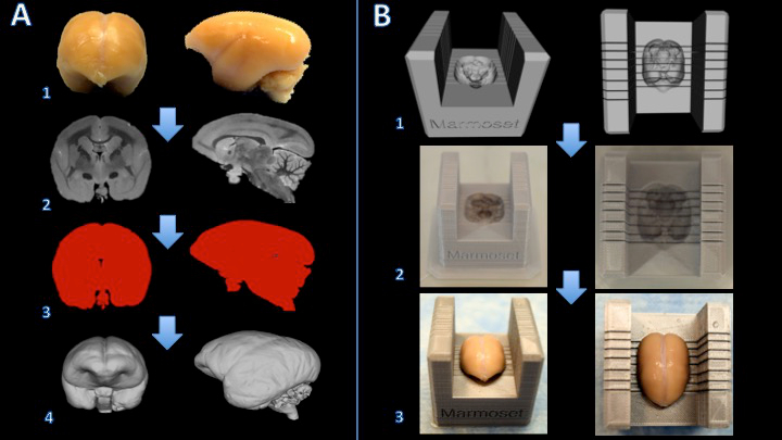
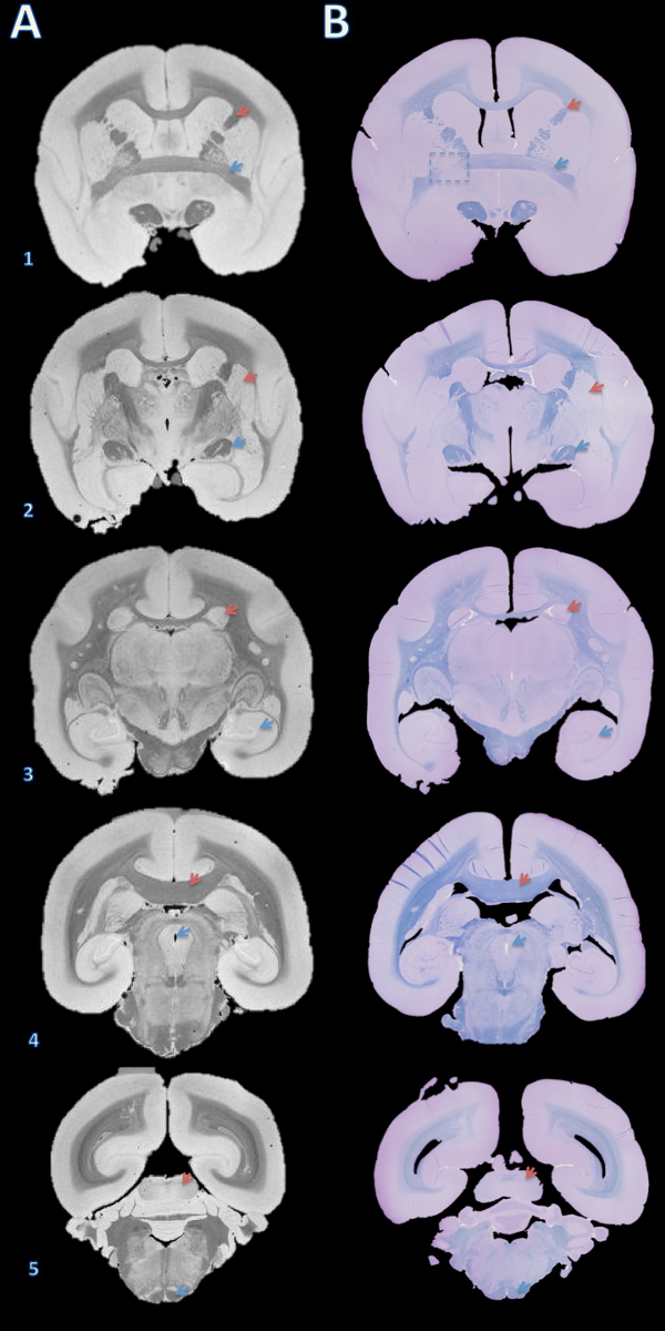
The workflow of this method is summarized in Figure 1. Once the brain is sliced, a visual comparison between the MR images and pictures of the superficial surfaces of the slabs shows a good orientation match across multiple slabs (Figure 2). After the slabs are embedded in paraffin, they are sectioned on a microtome and stained. A more thorough comparison between the high resolution postmortem MRI and the stained histology sections demonstrates an accurate and consistent match across all the structures of the marmoset brain (Figure 3).
In this animal model of MS, the animals develop white matter lesions spread throughout the cerebral white matter. These lesions can be detected noninvasively by performing MRI. Figure 4 demonstrates the ability of this technique to elucidate the pathological substrate of the MRI findings. Small lesions detected on in vivo MRI can be tracked on both postmortem MRI and histology. As shown in the insets, demyelination within the lesions is one of the main components driving the MR signal change (hyperintensity compared to surrounding tissue). The histology and postmortem MRI can also show lesions missed on in vivo MRI (Figure 4).

Figure 1. Workflow for creating a marmoset brain slicer box. The brain is fixed with formalin (A1) and a T2-weighted MRI is acquired with isotropic voxels of 150 µm per edge (A2). Images are processed and thresholded to create a binary mask (A3). The surface is then rendered in 3D modeling software (A4). A Boolean subtraction between a slicer template and the brain model creates a digital model of the brain slicer (B1). The brain slicer box is printed on a 3D printer (B2). The brain is then placed firmly in the slicer box for cutting (B3). Please click here to view a larger version of this figure.

Figure 2. From left to right: In vivo MRI, postmortem MRI, and tissue slab photograph. Slicing planes were established based on the postmortem MRI (B) and visually compared to the corresponding in vivo MRI slice (A). The brain was then cut, and the resulting slabs were found to be consistent (C). Please click here to view a larger version of this figure.

Figure 3. High-resolution postmortem MRI and histology section matching. Slabs were embedded in paraffin, cut with a microtome into 4 µm sections, and stained with fast blue and cresyl violet (B). The sections were then visually matched with the 100 µm T2*-weighted MRI based on brain structures (A). Details for acquiring this image are in the supplementary section of the protocol and Table 1. Brain structures: (1) red arrow = internal capsule, blue arrow = anterior commissure; (2) red arrow = putamen, blue arrow = optic tract; (3) red arrow = caudate, blue arrow = hippocampus; (4) red arrow = corpus callosum, blue arrow = cerebral aqueduct; (5) red arrow = inferior colliculus, blue arrow = pyramidal tract. The dashed box in B1 indicates a slice where, either during brain cutting or paraffin embedding, an error caused a slight rotation about the Y axis, leading to mismatch of the anterior commissure on the left. Please click here to view a larger version of this figure.

Figure 4. Tracking lesions from in vivo MRI to histology section. The in vivo MRI showed no convincing evidence of abnormal hyperintensity signal to suggest lesions in either optic tract (A1). However, the high resolution postmortem MRI shows clear hyper intense lines in both optic tracts (A2). The fast blue/cresyl violet stain of a 4 µm histology section shows that the hyperintense areas seen on the ex vivo MRI are demyelinated (A3). In the cerebral white matter, the in vivo MRI shows subtle hyperintensity bilaterally (B1, enlarged in the insets). The hyperintense areas are more obvious on the high resolution postmortem MRI (B2). The LFB stain of a 4 µm histology section shows that these areas are demyelinated (B3). After comparison with the baseline in vivo MRI and a hemotoxylin-and-eosin stain, the right side was determined to be an anatomical abnormality, not a demyelinated lesion. Please click here to view a larger version of this figure.

Supplemental code files. Brain_Slicer_Parts_Marmoset.stl: Please click here to download this file. Brain_Slicer_Parts_Human.stl: Please click here to download this file. Cap_Insert.stl: Please click here to download this file.
Discussion
The protocol outlined here enables an accurate comparison between MRI and histology sections. The protocol is presented in a unified format that can be applied to brains of humans or small animals, such as marmosets or rodents. Differences specific to large (human) and small (nonhuman primate and rodent) brains are highlighted, and in the accompanying video and figures we demonstrate the application in the marmoset. Although the approach is straightforward, the method requires many steps as well as the use of several types of software. Moreover, several issues potentially affecting the accuracy of this method are important to mention.
The image quality of the in vivo MRI is an important factor. To minimize the disparity in image resolution between MRI and digitalized histology images, the smallest possible MRI voxel size should be used. This concept also applies to the image quality of the postmortem MRI. While the increased acquisition time in postmortem MRI allows much higher image resolution, the preparation can introduce image artifacts such as focal signal dropouts related to air bubbles. These artifacts can obscure areas of the tissue as well as affect its contour. Moreover, the dimensions of the tissue on the postmortem MRI are likely to be affected by the fixation process and duration. While the in vivo to ex vivo MRI match can be closely approximated by utilizing anatomical landmarks in slice geometry setup during acquisition, a non-linear registration would still be necessary to reach a higher degree of accuracy in matching those two MRI images.
The design of the brain holder and slicer is also a crucial step. In creating the digital model of the brain, a smoothing algorithm is applied that slightly enlarges the model relative to the fixed brain. This enables easy insertion of the brain into its holder and slicer and reduces sharp edges in the holder's contour. However, if the model is too large (e.g., by more than 5%), the brain might move during the postmortem MRI and/or the sectioning. Another important point is to adapt the design of the brain model so that the cerebellum is properly placed inside the 3D printed object. This can be particularly challenging when the cerebellum has been damaged during the brain extraction at autopsy.
When printing the brain slicer and holder, the type of 3D printer must also be chosen carefully. Some multi-jet printers require post-processing using an oven to remove support material. While these printers can produce objects that are watertight and relatively more durable than desktop fused deposition modeling (FDM) printers, the heating process to remove supports can slightly warp the box, creating blade gaps that are not perfectly perpendicular to the brain contour.
The brain sectioning process is another crucial step. Before cutting the whole brain into slabs, it is important to make sure that the brain is sitting tightly inside the brain slicer: there should be no motion when slight pressure is applied onto the brain. This will make it possible for the blades to cut through the brain at the precise location set by the investigators. A continuous, balanced pressure should be applied to both blade holders when cutting. Depending on the sharpness of the blades and the rigidity of the tissue, a slight transverse cutting motion could be advantageous for maintaining flat cut surfaces.
The paraffin-embedding process can also be a source of misalignment between MRI and histology. If the tissue slab is not sitting flat against the cassette during the embedding process, there will be a tilt between the cutting plane of the microtome and the surface place of the slab. This will require cutting unusable sections to find a flat plane in which all the tissue is exposed. One way to correct for the tilt is by changing the angle of the viewing plane on the high-isotropic-resolution postmortem MRI. However, this is nearly impossible to perform on the in vivo MRI that is usually acquired with anisotropic resolution (typically thick coronal slices).
Finally, the tissue can experience some deformation during the formalin fixation period and paraffin embedding (shrinkage), as well as during the preparation of slides (folding, cracking, wrinkles). Some of these deformations can be corrected by putting the 4-5 μm sections in a water bath before transferring onto slides. Other deformations can be partially solved by performing deformable image coregistration of the histological digitized images to the postmortem MRI images. Nevertheless, minimizing the deformations with careful and skilled practice is the most effective approach to matching MRI volumes to histology sections.
In conclusion, the methodology introduced here enables investigators to accurately assess the underlying pathology of MRI findings. More generally, it is a promising approach for identifying and/or validating novel MRI biomarkers for research studies that target specific pathological processes, such as inflammation or remyelination.
Disclosures
The authors declare that they have no competing financial interests.
Acknowledgements
The Intramural Research Program of NINDS supported this study. We thank the NIH Functional Magnetic Resonance Imaging Facility. We thank Jennifer Lefeuvre and Cecil Chern-Chyi Yen for assistance with postmortem MRI acquisition. We thank John Ostuni and the Section on Instrumentation Core Facility for assistance with 3D printing. Figure 1 of this work used snapshots from MeshLab, a tool developed with the support of the 3D-CoForm project.
Materials
| Name | Company | Catalog Number | Comments |
| 7T/30cm USR AVIII Bruker MRI | Bruker Biospin | ||
| 38 mm Bruker Biospin volume coil | Bruker Biospin | ||
| Fomblin | Solvay Solexis | ||
| 50 ml Falcon Centrifuge Tubes, Polypropylene, Sterile | Corning | 21008-951 | |
| Fisherbrand Gauze Sponges | Fisher Scientrific | 13-761-52 | |
| Parafilm M All-Purpose Laboratory Film | Bemis | ||
| Leica RM2235 rotary microtome | Leica | ||
| Leica Disposable Blades, low profile (819) | Leica | ||
| Cresyl Violet Acetate, 0.1% Aqueous | Electron Microscopy Sciences | 26089-01 | |
| Luxol Fast Blue, 0.1% in 95% Alcohol | Electron Microscopy Sciences | 26056-15 | |
| ETOH | |||
| Ultimaker 2 Extended | Ultimaker | ||
| .75 kg Official Ultimaker Branded PLA Filament, 2.85 mm, Silver Metallic | Ultimaker | ||
| Axio Observer.Z1 | Zeiss | ||
| Zen 2 (Blue Edition) | Zeiss | ||
| Netfabb Professional 5.0.1 | Netfabb | http://www.netfabb.com/professional.php | |
| Meshmixer 10.9.332 | Autodesk | http://www.meshmixer.com/download.html | |
| Mipav 7.2 | NIH CIT | http://mipav.cit.nih.edu | |
| Cura | Ultimaker | https://ultimaker.com/en/products/cura-software | |
References
- Evans, A. C., Frank, J. A., Antel, J., Miller, D. H. The role of MRI in clinical trials of multiple sclerosis: comparison of image processing techniques. Ann Neurol. 41 (1), 125-132 (1997).
- 't Hart, B. A., van Kooyk, Y., Geurts, J. J. G., Gran, B. The primate autoimmune encephalomyelitis model; a bridge between mouse and man. Ann Clin Transl Neurol. 2 (5), 581-593 (2015).
- Ontaneda, D., Hyland, M., Cohen, J. A. Multiple sclerosis: new insights in pathogenesis and novel therapeutics. Annu Rev Med. 63, 389-404 (2012).
- Guy, J. R., Sati, P., Leibovitch, E., Jacobson, S., Silva, A. C., Reich, D. S. Custom fit 3D-printed brain holders for comparison of histology with MRI in marmosets. J Neurosci Methods. 257, 55-63 (2016).
- Breen, M. S., Lazebnik, R. S., Wilson, D. L. Three-dimensional registration of magnetic resonance image data to histological sections with model-based evaluation. Ann Biomed Eng. 33 (8), 1100-1112 (2005).
- Dauguet, J., et al. Three-dimensional reconstruction of stained histological slices and 3D non-linear registration with in-vivo MRI for whole baboon brain. J Neurosci Methods. 164 (1), 191-204 (2007).
- McGrath, D. M., Vlad, R. M., Foltz, W. D., Brock, K. K. Technical note: fiducial markers for correlation of whole-specimen histopathology with MR imaging at 7 tesla. Med Phys. 37, 2321-2328 (2010).
- Schormann, T., Zilles, K. Three-Dimensional linear and nonlinear transformations: An integration of light microscopical and MRI data. Hum Brain Mapp. 6, 339-347 (1998).
- Jiang, L., et al. Combined MR, fluorescence and histology imaging strategy in a human breast tumor xenograft model. NMR Biomed. 26 (3), 285-298 (2013).
- Absinta, M., et al. Postmortem magnetic resonance imaging to guide the pathologic cut: individualized, 3-dimensionally printed cutting boxes for fixed brains. J Neuropathol Exp Neurol. 73 (8), 780-788 (2014).
- Gaitán, M. I., et al. Perivenular brain lesions in a primate multiple sclerosis model at 7-tesla magnetic resonance imaging. Mult Scler. 20 (1), 64-71 (2014).
Reprints and Permissions
Request permission to reuse the text or figures of this JoVE article
Request PermissionThis article has been published
Video Coming Soon
Copyright © 2025 MyJoVE Corporation. All rights reserved