An Experimental Protocol for Femtosecond NIR/UV - XUV Pump-Probe Experiments with Free-Electron Lasers
In This Article
Summary
This protocol describes the key steps for performing and analyzing pump-probe experiments combining a femtosecond optical laser with a free-electron laser in order to study ultrafast photochemical reactions in gas-phase molecules.
Abstract
This protocol describes key steps in performing and analyzing femtosecond pump-probe experiments that combine a femtosecond optical laser with a free-electron laser. This includes methods to establish the spatial and temporal overlap between the optical and free-electron laser pulses during the experiment, as well as important aspects of the data analysis, such as corrections for arrival time jitter, which are necessary to obtain high-quality pump-probe data sets with the best possible temporal resolution. These methods are demonstrated for an exemplary experiment performed at the FLASH (Free-electron LASer Hamburg) free-electron laser in order to study ultrafast photochemistry in gas-phase molecules by means of velocity map ion imaging. However, most of the strategies are also applicable to similar pump-probe experiments using other targets or other experimental techniques.
Introduction
The availability of short and intense extreme ultraviolet (XUV) and X-ray pulses from free-electron lasers (FELs)1,2 has opened up new opportunities for femtosecond pump-probe experiments exploiting the site- and element-specificity of the inner-shell photo-absorption process3,4,5,6. Such experiments can be used, e.g., to investigate molecular dynamics and charge transfer processes in liquids7 and gas-phase molecules8,9,10,11,12, and for real-time observations of catalytic reactions and ultrafast surface chemistry13,14 with a temporal resolution of 100 femtoseconds or below. If the pump-probe experiment is performed by combining a synchronized optical femtosecond laser with the FEL, which was the case in all of the examples mentioned above, the intrinsic arrival-time jitter between the optical laser and the FEL pulses has to be measured on a shot-by-shot basis and corrected for in the data analysis in order to achieve the best temporal resolution possible.
Within a large collaboration, several pump-probe experiments combining optical lasers with a free-electron laser have recently been performed9,10,11,12, both at the FLASH XUV FEL15,16 and the LCLS X-ray FEL17 facilities, and an experimental protocol for performing and analyzing these experiments has been developed, which is presented in the following. The method is demonstrated for an exemplary experiment performed at the FLASH free-electron laser in order to study ultrafast photochemistry in gas-phase molecules by means of velocity map ion imaging11,12. However, most of the strategies are also applicable to similar pump-probe experiments using other targets or other experimental techniques and can also be adapted to other FEL facilities. While some of the individual steps presented here or variations thereof have already been discussed in the literature18,19,20, this protocol provides a comprehensive description of the key steps, including some that take advantage of the most recent technical improvements in the synchronization and in the timing diagnostics, which have considerably improved the stability and the temporal resolution for pump-probe experiments12,21.
The following protocol assumes a pump-probe end-station, such as the CAMP instrument at FLASH22, equipped with an ion time-of-flight, an ion momentum imaging, or a velocity map imaging (VMI) ion spectrometer; an effusive or supersonic gas jet; and a synchronized near-infrared (NIR) or ultraviolet (UV) femtosecond laser, whose pulses can be overlapped collinearly or near-collinearly with the free-electron laser beam, as sketched schematically in Figure 1. Furthermore, an appropriate suite of diagnostics tools such as a removable beam viewing screen (e.g. a paddle coated with Ce:YAG powder or a thin Ce:YAG crystal) in the interaction region, a fast photodiode sensitive to both FEL and laser pulses, and a bunch arrival-time monitor (BAM)23,24 or "timing tool"25,26,27 are required, all of which are usually integrated in the pump-probe end-station or are provided by the FEL facility, if requested before the experiment. Finally, the shot-by-shot jitter correction assumes that the experimental data is recorded and accessible on a shot-by-shot basis and linked to the shot-by-shot measurements of the bunch arrival-time time jitter by using a unique "bunch ID" or by another equivalent scheme.
At FLASH, the specific systems that are crucial for pump-probe experiments are:
- The active, all-optical feedback and stabilization system of the pump-probe laser to the master laser oscillator, which includes a balanced optical cross-correlator that stabilizes the pump-probe laser's oscillator output to the master laser oscillator, and a cross-correlator ("drift correlator") to correct for slow drifts of the laser amplifier with respect to the oscillator21.
- The bunch arrival-time monitors (BAMs) that measure the shot-to-shot variations in the electron bunch arrival time at various positions in the accelerator with respect to the master laser oscillator23,24. They can be used for an active-feedback loop to stabilize the timing of the electron bunches with respect to the master laser oscillator, thus reducing slow drifts in the arrival time. Moreover, the BAM located closed to the experiment (BAM 4DBC3) can be used for a shot-to-shot jitter correction in the data analysis, which is in detail in step 5.1 of the experimental protocol.
- The pump-probe laser streak camera, which measures the relative timing between the pump-probe laser output and the dipole radiation generated by the electron bunch at the end of the accelerator before it is guided into the beam dump28.
- The focus camera, which images the "virtual" laser focus by using the part of the laser beam that is leaking through the last turning mirror behind the focusing lens in order to parasitically monitor slow spatial drifts of the optical laser.
Similar systems are available at other FEL facilities and are crucial for performing a reliable pump-probe experiment.
Protocol
Caution: Before starting this procedure, it is very important to become familiar with all possible hazards connected to the experiment. The procedure below includes class-IV lasers, XUV or X-ray radiation, high-voltage sources, compressed gases, and harmful or toxic chemicals. Please consult all relevant material safety data sheets (MSDS) before use and follow all safety requirements mandated by the FEL and laser facility.
1. Preparation
NOTE: Before the start of the experiment, several choices have to be made, e.g., regarding the optimal choice of pump and probe wavelengths and intensities for the target of interest and the appropriate type of spectrometer to measure the required observables (see, e.g., Fang et al. 20144 and Rudenko et al. 20155). In the following, these technical aspects related to the specific processes and targets that shall be studied are not discussed, and it is assumed that the appropriate beam parameters for the FEL and the optical laser for the planned experiment have been determined and set up and that a suitable ion spectrometer is installed and operational.
- Alignment and pointing stability of FEL and laser beams
- At the beginning of the experiment, monitor the shot-by-shot and the long-term pointing stability of both FEL and optical laser beams on the removable beam viewing screen in the interaction region and improve the stability of the laser setup and the FEL lasing process, if necessary.
NOTE: To perform a reliable pump-probe experiment, it is crucial that both FEL and optical laser beams are optimally aligned through the entire beamline/beam path and that pointing instabilities of both beams are smaller than their spot size in the focus. The sizes of the focused optical laser and FEL beams are typically on the order of a few to a few tens of micrometers, so the spatial resolution of the beam viewing screen and the optics and the camera that are used to image this screen (e.g. a long-distance microscope) needs to be sufficiently high to accurately determine the position of both beams. - Avoid or minimize any clipping of the FEL beam between the experiment and the location where the FEL pulse energy is measured by centering the beam on all transport mirrors and apertures in the beamline. Any apertures that can clip the beam when the beam pointing changes on a shot-by-shot basis or by slow drifts during the course of a delay scan may compromise the ability to normalize the data on the FEL pulse energy.
- Optimize the position of the gas jet and the spectrometer with respect to the position of the FEL focus and the focus of the optical laser in all three spatial dimensions. Depending on the details of the setup, this may be done by moving the vacuum chamber or by moving individual components, and/or by moving the focus position of the FEL and the optical laser beam.
- At the beginning of the experiment, monitor the shot-by-shot and the long-term pointing stability of both FEL and optical laser beams on the removable beam viewing screen in the interaction region and improve the stability of the laser setup and the FEL lasing process, if necessary.
- Proper functioning of feedback systems and diagnostics tools
Ensure that all necessary feedback systems and diagnostics and monitoring tools are enabled, properly functioning, and – where necessary – that their data is recorded in the FEL machine data stream. At FLASH, these include the all-optical feedback and stabilization system of the pump-probe laser; the bunch arrival-time monitors (BAMs); pump-probe laser streak camera; and the virtual focus camera. See the Introduction for a more detailed description of these systems.
NOTE: It is strongly advisable to continuously monitor these systems while performing the pump-probe experiment in order to be aware of possible problems, e.g., with the laser synchronization system, as quickly as possible.
2. Establishing Spatial Overlap Between the FEL beam and the Optical Laser Beam
- Overlapping the beams visually on a Ce:YAG beam viewing screen in the interaction region
- Make sure the ion (and electron) detector and the high voltage on the ion spectrometer electrodes are turned off before proceeding.
- Reduce the FEL pulse energy and the power of the optical laser using the filters and attenuators installed in the beamline to less than 1% transmission in order to avoid damage of the viewing screen by the focused beams.
- Insert the beam viewing screen into the interaction region. If you are unable to detect the beam spots, slightly increase their intensities.
NOTE: Depending on the experimental geometry (fully collinear or near-collinear, i.e., with the optical laser beam aligned at a small angle with respect to the FEL beam, e.g. to avoid losing too much power in the hole of the drilled incoupling mirror), it may be crucial that the screen is situated exactly at the position of the interaction region, since even a small displacement of a few millimeters can cause a misalignment of the beams in the case of near-collinear geometry. - Block the optical laser by closing the laser shutter and mark the position of the FEL beam on the viewing screen by creating a "region of interest (ROI)" using the camera data acquisition software.
- Block the FEL beam by closing the FEL shutter and inspect the position of the optical laser beam on the viewing screen. Using the appropriate steering mirrors for the optical laser, align the laser beam to overlap with the marked position of the FEL spot.
NOTE: For most pump-probe experiments, it is beneficial to use a spot size of the pump beam that is larger than the spot size of the probe beam. This facilitates finding good spatial overlap and makes the experiment more robust to small pointing fluctuations, thus minimizing the probability of probing a region of space where the target has not been excited by the pump pulse. In general, a larger pump than probe spot also ensures more homogeneous excitation. - Repeat steps 2.1.4 and 2.1.5 to fine-tune the overlap and to verify that the overlap is stable.
- Remove beam viewing screen. Then, turn on detectors and spectrometer high voltages.
NOTE: If the visual overlapping of the beams on the viewing screen in the interaction region does not give satisfactory results, i.e., if a two-color signal cannot be found in the subsequent steps described in step 3.2, the spatial overlap between the beams may be defined more precisely using the ion signal, as described in step 2.2, if an ion imaging spectrometer is available. This procedure is also described in Johnsson et al. 201019.
- Overlapping the beams using the ion time-of-flight signal and the ion images
- Overlap in the detector plane
- Set the spectrometer voltages to "spatial imaging mode", i.e., such that the ion detector image is a direct, magnified image of the interaction region. The voltage settings for this mode depend on the specific spectrometer.
- Choose the ion image corresponding to a non-fragmented molecular parent ion or use an atomic target and choose an ionic charge state that is produced by both the FEL and the optical laser alone, e.g. H2O+ ions from the residual gas inside the vacuum chamber. If necessary, reduce the FEL or laser intensity to produce such a charge state. Avoid using a target that is introduced by a supersonic beam, since the beam velocity may falsify the procedure.
- Block the optical laser using the laser shutter and mark the hit position of the ions produced by the FEL beam.
- Block the FEL beam using the FEL shutter and record the position of the same ion species produced by the optical laser beam. Using the appropriate steering mirrors for the optical laser, align the laser beam until the ion hit positions overlap as well as possible with the marked position of the ions produced by the FEL beam.
- In order to overlap the foci of the two beams along the beam propagation direction, move the focusing lens of the laser until the laser focus is centered in the spectrometer.
- Repeat steps 2.2.1.3 and 2.2.1.4 to fine-tune the overlap and to verify that the overlap is stable.
- Overlap in the time-of-flight direction
- Operate the spectrometer in a "time-of-flight mode", i.e., such that the ion detection timing signal (i.e., the ion time-of-flight spectrum) can be monitored on a fast oscilloscope or digitizer, which is triggered by the FEL master trigger. Avoid operating the spectrometer in Wiley-McLaren conditions such that the time of flight is sensitive to the starting position along the spectrometer axis.
- In the ion time-of-flight spectrum, identify and zoom in on the peak corresponding to the same ion used in 2.2.1.2.
- Block the optical laser using the laser shutter and precisely mark the center of the time-of-flight peak produced by the FEL beam alone.
- Block the FEL beam using the FEL shutter and find the center of the same time-of-flight peak produced by the optical laser beam alone. Using the appropriate steering mirrors for the optical laser, align the laser beam until the time-of-flight peak produced by the optical laser beam overlaps perfectly with the marked center of the peak produced by the FEL beam.
NOTE: This only works if the arrival times of the optical laser pulses and the FEL pulses are within roughly a nanosecond of each other. If in doubt, perform the "rough timing" step described in step 3.1 before doing the spatial overlap procedure. - Repeat steps 2.2.2.3 and 2.2.2.4 to fine-tune the overlap and to verify that the overlap is stable.
- Overlap in the detector plane
3. Establishing Temporal Overlap Between the FEL Pulses and the Optical Laser Pulses
- "Rough" timing
NOTE: The rough timing between the FEL pulses and the optical laser pulses to a precision of a few tens of picoseconds can be determined using a fast photodiode connected, via a short SMA cable, to a "bias T" with a 9 V battery connected at "DC in" and a fast (≥10 GHz) oscilloscope, which is triggered by the FEL master trigger. Typically, the diode is not placed directly into the FEL and laser beams since this could destroy the diode. Instead, it is installed perpendicular to the FEL beam, and a movable mesh is used to send a small amount of scattered photons to the diode.- Reduce the FEL pulse energy and the power of the optical laser using the filters and attenuators installed in the beamline to the point where the signal from the scattered light will not destroy the photodiode. A safe starting point is typically a transmission value of 1% (i.e., 99% attenuation).
- Insert the scattering mesh into the beam. Optimize the position of the mesh and the FEL pulse energy and laser power such that each beam alone yields a clear signal and that both signals have the same height.
- Block the optical laser using the laser shutter and, with the finest time base available, save a reference trace on the oscilloscope using about 100 averages.
- Block the FEL beam using the FEL shutter and compare the resulting trace from the laser signal with the FEL reference. Using the appropriate delay stage for the optical laser, shift the arrival time of the laser pulse until the onset of the laser signal is precisely at the position of the onset of the FEL signal.
- Repeat steps 3.1.3 and 3.1.4 to verify that the FEL and laser pulses are as close to each other in time as possible based on the resolution of the photodiode.
- If, as a result of the above procedure, the laser pulse was shifted in time by more than 1 nanosecond, repeat step 2.2.2 ("overlap in the time-of-flight direction") with the new laser timing.
- "Fine" timing
NOTE: The precise time T0, when FEL and laser pulses are exactly overlapped in time, can be found using a two-color (FEL + laser) signal that exhibits a maximum or a "step function"-like increase or decrease, e.g., in the ion yield or kinetic energy of a given ionic fragment. As the appropriate method depends on the FEL and laser wavelengths, several methods are described in the following.- T0 determination for XUV + NIR pulses using xenon gas
NOTE: This method is suitable for 800 or 400-nm laser pulses and XUV pulses above the Xe(4d) ionization threshold at 67.5 eV.- Attenuate the FEL and the optical laser to avoid damaging the ion (and electron) detector(s) with an excessive count rate due to high absorption cross-sections of xenon.
- Introduce Xe gas into the chamber either through the gas jet or by leaking it into the vacuum through a needle valve. In the latter case, adjust the pressure to be between 1 x 10⁻⁷ and 1 x 10⁻⁶ mbar.
- Record the ion time-of-flight spectrum. Block the laser using the laser shutter and adjust the FEL pulse energy such that the ion time-of-flight spectrum is dominated by single-photon processes, i.e., such that the Xe2+ and Xe3+ peaks are the strongest Xe charge states in the time-of-flight spectrum and higher charge states are (almost) absent. If necessary, adjust the Xe pressure such that both peaks are well within the dynamic range of the detector and the data acquisition system.
- Block the FEL using the FEL shutter and unblock the laser. Adjust the laser power such that the laser pulses produce mostly Xe+ and only a small amount of Xe2+.
- Unblock the FEL and set the timing between the FEL and the laser such that the laser pulses arrive about 200 ps before the FEL pulses (based on the approximate reading of T0 obtained from the "rough" timing method described in step 3.1). Record the ion time-of-flight spectrum and determine the ratio of Xe2+ to Xe3+ from the area of the corresponding peaks in the time-of-flight spectrum.
- Set the timing between the FEL and the laser such that the laser pulses arrive about 200 ps after the FEL pulses based on the T0 obtained from the "rough" timing method. Record the Xe ion time-of-flight spectrum and determine the ratio of Xe2+ to Xe3+. If the spatial overlap between FEL and laser pulses is good, it will change significantly from the ratio obtained in step 3.2.1.5, with the Xe3+ signal now being stronger than in step 3.2.1.5, as shown in Figure 2.
- Set the laser timing halfway in between the values in step 3.2.1.5 and 3.2.1.6.
- Record the ion time-of-flight spectrum and determine the ratio of Xe2+ to Xe3+. If the ratio is similar to the one in step 3.2.1.5, the laser pulses still arrive before the FEL pulses. If the ratio is similar to the one in step 3.2.1.6, the laser pulses still arrive after the FEL pulses.
- If the laser pulses are still arriving before the FEL pulses (i.e., ratio similar to step 3.2.1.5), set the timing half way in between the current value and the value in step 3.2.1.6), otherwise set it half way in between the current value and the value in step 3.2.1.5).
- Repeat 3.2.1.8 and 3.2.1.9 until the position of T0 has been narrowed down to a precision of better than 500 fs.
- Set up a delay scan over a region of +/- 1 ps around the approximate position of T0 in steps of 50 fs (or smaller, depending on the NIR and FEL pulse duration). Record the time-of-flight spectrum and determine the ratio of Xe2+ to Xe3+ for every step. The center of the "step function" in the signal will yield the exact position of T0.
- T0 determination for XUV + NIR or UV pulses using CH3I
NOTE: This method is suitable for XUV pulses above the I(4d) ionization threshold at ~57 eV and for either 266-nm or 800-nm laser pulses (400 nm is untested, but probably also possible). It can also be performed using CF3I instead of CH3I.- Attenuate the FEL and the optical laser to avoid damaging the detector with an excessive count rate.
- Introduce CH3I molecules into the chamber either through the gas jet or by leaking it into the vacuum through a needle valve. In the latter case, adjust the pressure to be between 1 x 10⁻⁷ and 1 x 10⁻⁶ mbar. If the vapor pressure of the CH3I sample is not sufficient to form a molecular beam, use He as a carrier gas.
- Record the ion time-of-flight spectrum. Block the laser using the laser shutter and adjust the FEL pulse energy to the highest available pulse energy.
- Block the FEL using the FEL shutter. When using 266-nm pulses, adjust the laser power such that the laser produces CH3I+ ions and a small amount of I+ and CH3+. When using 800-nm pulses, adjust the laser power such that the laser produces a significant amount of CH3I+, I+, and CH3+ ions, but only few more highly charged ions.
- Set the timing between the FEL and the laser such that the laser pulses arrive about 200 ps before the FEL pulses (based on the approximate reading of T0 obtained from the "rough" timing method described in step 3.1). Record the ion time-of-flight spectrum or, when using a velocity map imaging (VMI) spectrometer, the ion image for the I4+ fragment (for photon energies below 600 eV, the I3+ fragment can also be used). Adjust the spectrometer voltages such that the time-of-flight peaks corresponding to the singly and multiply charged iodine fragments are broad (because of their large kinetic energy) or, when using a VMI spectrometer, such that the I4+ ion image covers most of the detector.
- In the ion time-of-flight spectrum, the peak corresponding to the I4+ fragment (as well as the peaks corresponding to higher iodine charge states) will have a narrow spike in the middle (see Figure 3A). When using a VMI spectrometer, one or two (depending on the spectrometer resolution and the direction of the laser polarization) small bright spots will appear close to the center of the I4+ ion image (see Figure 3B). If these features do not appear, either timing or spatial overlap are not correct.
- Set the timing between the FEL and the laser such that the laser pulses arrive about 200 ps after the FEL pulses based on the T0 obtained from the "rough" timing method. Record the ion time-of-flight spectrum or the ion image for the I4+ fragment. The spike in the middle of the TOF peaks and the bright spot(s) in the center of the VMI images will disappear.
- Set the laser timing half way in between the values in step 3.2.2.5 and 3.2.2.6.
- Record the ion time-of-flight spectrum or the I4+ ion image and determine if the spikes or the spot(s) are present or not. If they are present, the laser pulses still arrive before the FEL pulses. If they are not, the laser pulses still arrive after the FEL pulses.
- If the laser pulses are still arriving before the FEL pulses, set the timing half way in between the current value and the value in step 3.2.2.6, otherwise set it half way in between the current value and the value in step 3.2.2.5.
- Repeat 3.2.2.8 and 3.2.2.9 until the position of T0 has been narrowed down to a precision of better than 500 fs.
- Set up a delay scan over a region of +/- 1 ps around the approximate position of T0 in steps of 50 fs. Record the time-of-flight spectrum or the ion image for the I4+ fragment for every step. Plot the yield of the spike or bright spots as a function of delay. The center of the "step function" in the signal is at a delay of ~120 - 150 fswith respect to T09,10.
- T0 determination for XUV + NIR pulses using xenon gas
4. Fine-Tuning the Spatial Overlap on a Two-Color Signal
NOTE: While the procedure to establish the spatial overlap described in steps 2.1 and 2.2 is usually precise enough to be able to observe the two-color signal described in the procedure for establishing the temporal overlap (step 3), it is often advisable to fine-tune the spatial overlap on this two-color signal before starting the actual pump-probe experiment.
- In order to fine-tune the spatial overlap, carefully adjust the mirrors that determine the spatial overlap and thereby maximize the Xe2+ to Xe3+ ratio when the laser pulses arrive approximately 1 ps after the FEL pulses.
- Alternatively, if the temporal overlap procedure is performed with CH3I, maximize the yield of the low-energy component in the I4+ fragments when the laser pulses arrive approximately 1 ps before the FEL pulses.
NOTE: Ideally, this fine-tuning procedure is repeated using a two-color signal in the actual target molecule, once such a signal has been found.
5. Arrival-Time Jitter-Correction in the Data Analysis
NOTE: In order to achieve the best temporal resolution possible, the single-shot data has to be corrected for the shot-to-shot arrival-time fluctuations as measured by the bunch arrival-time monitor (BAM) or timing tool, as described, e.g., in Savelyev et al. 201712.
- Arrival-time jitter correction based on BAM data
NOTE: In order to determine a unique and universal value for T0, the same procedure for the arrival-time jitter correction has to be performed both on the data from which T0 is determined (e.g. the data obtained in step 3.2) and for the actual experimental data of interest. For the sake of the following description, it is assumed that T0 is determined by measuring Xe ion time-of-flight traces. The protocol can be applied equivalently in the other cases.- Plot the streak camera values, the laser timing jitter, and the BAM values as a function of shot number for the entire range of the pump-probe scans of interest. If there are large, sudden jumps of more than 1 ps, this may be an indication of a loss of laser lock or another technical problem during this particular scan. Some of the data in that region may not be amenable for the correction described in the following and may have to be discarded.
- Plot a histogram of the BAM values for the BAM located closed to the experiment (BAM 4DBC3) for each shot of the delay scan taken in step 3.2.1.11.
- Chose a value close to the center of the distribution and define it as the reference value BAM0.
- For each shot of the delay scan, calculate the corrected delay Dn, where n is the shot number, as
Dn = Pn + (BAMn – BAM0) (1)
where Pn is the delay stage position and BAMn is the BAM value for the nth shot. Note that more positive BAM values mean a larger delay between the laser and the FEL pulse, i.e., the FEL arriving later. - Sort the single-shot time-of-flight traces in suitable delay bins based on their corrected delay value and determine the center position of the step function in the Xe2+ to Xe3+ ratio, which yields the corrected position of T0.
- Using the same value for BAM0 as in step 5.1.4), calculate the corrected delay Dn for each shot of the delay scan with the actual pump-probe data of interest using eq. (1).
Results
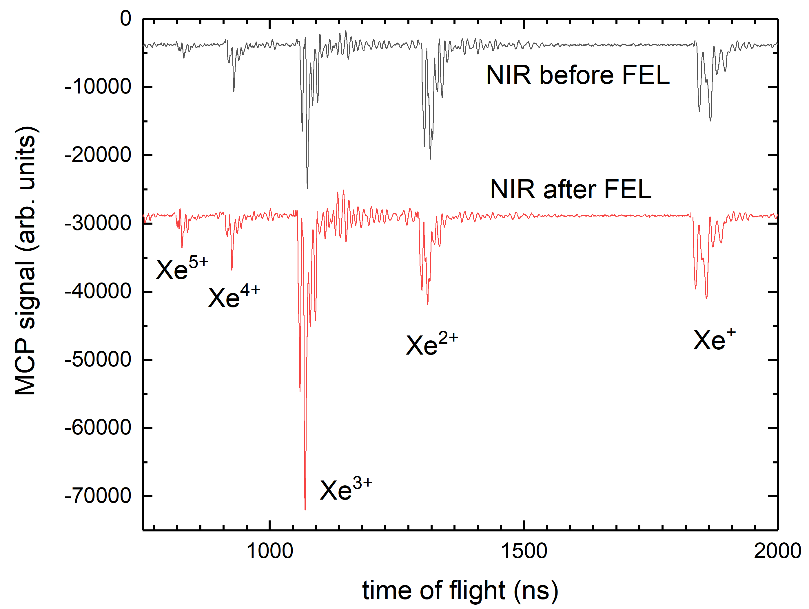
If the FEL and the optical laser pulses are spatially overlapped in the interaction region of the ion spectrometer, the temporal overlap, i.e., the delay value T0, at which FEL and laser pulses arrive exactly at the same time, can be found by varying the delay between FEL and NIR pulses and by analyzing the ratio of the Xe2+ to Xe3+ ion yield as a function of delay, as explained above in section 3.2.1. When the NIR pulse arrives after the FEL pulse (which needs to have a photon energy of 67.5 eV or higher), the Xe3+ ion yield is increased due to post-ionization of excited, metastable Xe2+ ion that are created during the Auger decay process following the Xe(4d) inner-shell ionization18, as shown in Figure 2. Plotting the ratio of the Xe2+ to Xe3+ ion yield as a function of delay thus yields a step function, which can be fitted to extract the exact value of T0.
A similar step function can be obtained by varying the delay between FEL and laser pulses and by analyzing the ion time-of-flight traces or ion momentum images of highly charged iodine ions, such as I3+ or I4+, created in the ionization of CH3I, as explained above in step 3.2.2). In this case, a low-energy contribution will appear as an additional peak at center of the highly charged iodine peaks in the time-of-flight spectrum or as a bright spot at the center of the corresponding momentum images, as shown in Figure 3. The low-energy ions are created when the CH3I molecules are first dissociated by the laser pulse and the ion fragment is then post-ionized by the FEL pulse9,10. This method can be used if either NIR or UV pulses are used for the pump-probe experiment, as long as the FEL photon energy is higher than 57 eV, which is the iodine 4d inner-shell ionization threshold in CH3I.
In order to correct for the jitter in the relative arrival time of the FEL pulses with respect to the laser pulses, the shot-by-shot data recorded by the bunch arrival-time monitor (BAM), shown in Figure 4, can be used to sort the recorded pump-probe data in the post-analysis, as explained above in section 5. This typically improves the temporal resolution and overall quality of the pump-probe data considerably, as shown in Figure 4 and, in more detail, in Savelyev et al. 201712.

Figure 1: Experimental Setup. Sketch of the experimental setup for a UV-pump XUV-probe experiment on gas-phase molecules. The UV (266 nm) laser beam is produced as the third harmonic of an 800-nm Titanium:Sapphire (Ti:Sa) beam using Beta Barium Borate (BBO) crystals and compressed using a prism compressor. It is collinearly overlapped with the XUV FEL beam using a drilled mirror and focused inside a supersonic gas beam at the center of a double-sided velocity map imaging spectrometer22,29. Ion and electron momentum distributions are recorded at opposite ends of the spectrometer using a MCP/phosphor screen assembly followed by a CCD camera. Please click here to view a larger version of this figure.

Figure 2: Delay-dependence of the Xe ion yield. Xe ion time-of-flight spectrum (decoupled MCP signal recorded by a fast digitizer) at 83 eV photon energy and with the NIR laser pulses arriving 1 μs before (top, black trace) and after (bottom, red trace) the FEL pulses. The change in the Xe2+ to Xe3+ ratio is clearly visible. Please click here to view a larger version of this figure.

Figure 3: Delay-dependence of the iodine ion yield and momentum. (A) Zoom-in on the I4+ peak in the ion time-of-flight spectrum of CH3I recorded at 727 eV photon energy and with the UV laser pulses arriving before (red line) and after (black line) the FEL pulses. The blue and green line, respectively, show the time-of-flight spectrum for FEL and UV laser pulse alone. This figure has been modified from Boll et al. 201610. (B) Ion momentum image of I3+ ions from CH3I recorded at 107 eV photon energy and with the UV laser pulses arriving before the FEL pulses. (C) Same as (B), but with the UV pulses arriving after the FEL pulses. The color scale in (B) and (C) shows the ion yield in arbitrary units. Please click here to view a larger version of this figure.

Figure 4: Relative arrival time jitter of the FEL pulses with respect to the optical laser pulses. (A) Shot-by-shot bunch arrival-time monitor (BAM) data for all FEL shots recorded during an exemplary delay scan. The reference value BAM0 was set to the mean BAM value for this scan. (B) Ion yield of low kinetic-energy I3+ ions produced in a UV-XUV pump-probe experiment on difluoroiodobenzene before correction of the shot-to-shot arrival jitter. The red line shows a least-squares fit of a cumulative distribution function (Gauss error function) to the experimental data. The fit parameter σ is a measure of the total temporal resolution of the pump-probe experiment. (C) Same as in (B) but with the single-shot images resorted into new delay bins using the BAM data. The error bars represent one standard deviation. Figure adapted from Savelyev et al. 201712. Please click here to view a larger version of this figure.
Discussion
Due to the complexity of the experimental setups, pump-probe experiments with free-electron lasers require a high level of expertise and experience and need very careful preparation and detailed discussions with the scientific teams that operate the free-electron laser, the optical laser, and the end-station, both before and during the experiment. While performing the actual experiment, precise determination of spatial and temporal overlap and close monitoring of all diagnostics and timing systems, as described in this protocol, are essential.
Note that most of the methods described here are only applicable for a specific photon energy range of the FEL since they rely on effects that strongly depend on the photon energy. For example, the determination of the "rough" temporal overlap using scattered light directed on a photodiode was found to work well for photon energies up to ~250 eV. At higher photon energies, the signal generated by the FEL pulses becomes so small that it is hard to detect. In that case, an open-ended SMA cable that can be brought very close (less than a millimeter) to or even into the FEL beam was found to produce a more reliable signal to perform the procedure described in step 3.1) of the protocol. Similarly, the best target for determining the "fine" timing, described in step 3.2), is strongly dependent on the photon energy. For FEL pulses in the XUV and soft X-ray region above 65.7 eV and ~57 eV photon energy (corresponding to the 4d ionization thresholds in xenon and CH3I, respectively), Xe and CH3I were found to be suitable targets for the procedure described in step 3.2. The method using CH3I was found to work for photon energies up to 2 keV (above which it has not yet been tested), while the method using Xe has been tested up to 250 eV. For photon energies below 50 eV, the bond softening process in H2 can be used19. At photon energies above 400 eV, a similar process in N2 is also suitable20. Alternative approaches involve the change in reflectivity of a solid sample25,26,30 or the formation of side bands in the photoelectron spectrum31,32.
In order to achieve the best temporal resolution, it is necessary to sort the experimental data on a shot-by-shot basis in the data analysis to compensate for the arrival time jitter between the FEL and the optical laser pulses, as described in step 5. However, the quality of the pump-probe data and, in particular, the achievable temporal resolution, strongly depends on the performance of the FEL during the experiment and on the pulse durations of the optical laser pulses and the FEL pulses that can be provided during that time. For the exemplary data shown here, the pulse duration of the UV pulses was estimated to be 150 fs (FWHM) and the FEL pulse duration was estimated to be 120 fs (FWHM). Although the total arrival time-jitter of approximately 90 fs (rms) before jitter-correction could be reduced to approximately 27 fs (rms) using the procedure described here12, the resulting improvement of the total temporal resolution of the experiment was rather small because of the relatively long pulse durations of the FEL and the optical laser. Both can, however, be reduced substantially, in which case the impact of the jitter correction scheme will be more significant. For example, a new optical laser is currently being installed at FLASH, which will have a pulse duration (in the near-infrared) below 15 fs, while new FEL operation modes are also being tested that can produce FEL pulses with pulse durations of a few femtoseconds or even below. These developments will soon enable pump-probe experiments combining FEL and optical laser pulses with an overall temporal resolution of only a few tens of femtoseconds.
While the increased availability of short and intense XUV and X-ray pulses produced by FELs has spawned a number of NIR/UV - XUV pump-probe experiments such as the one described here, similar pump-probe experiments can also be performed with high harmonic generation (HHG) sources33,34,35. The main limitation of the FEL-based experiments is typically the achievable temporal resolution, which is fundamentally limited by the synchronization between the FEL and the optical laser or by the precision with which the relative timing between the pump and the probe pulses can be measured. This is not the case for a HHG-based pump-probe experiment, where the XUV and NIR pulses are intrinsically synchronized with sub-cycle precision and which can therefore, in general, have a much higher temporal resolution. The major advantage of the FEL-based experiments, on the other hand, is the several orders of magnitude higher photon fluence, which enables experiments, e.g., on dilute targets that are not be feasible with current HHG sources, especially at higher photon energies in the soft X-ray regime. For the foreseeable future, pump-probe experiments with FELs and HHG will therefore remain complementary, with some overlap in the XUV region where both can be used for similar investigations. Some of the steps to perform these experiments are also similar, and some of the methods described here can therefore also be applied for HHG-based pump-probe experiments.
Disclosures
The authors declare no competing interests.
Acknowledgements
The authors thank Evgeny Savelyev, Cédric Bomme, Nora Schirmel, Harald Redlin, Stefan Düsterer, Erland Müller, Hauke Höppner, Sven Toleikis, Jost Müller, Marie Kristin Czwalinna, Rolf Treusch, Thomas Kierspel, Terence Mullins, Sebastian Trippel, Joss Wiese, Jochen Küpper, Felix Brauβe, Faruk Krecinic, Arnaud Rouzée, Piotr Rudawski, Per Johnsson, Kasra Amini, Alexandra Lauer, Michael Burt, Mark Brouard, Lauge Christensen, Jan Thøgersen, Henrik Stapelfeldt, Nora Berrah, Maria Müller, Anatoli Ulmer, Simone Techert, Artem Rudenko, Daniela Rupp, and Melanie Schnell, who participated in the FLASH beamtime during which the specific data shown and discussed here were acquired and who contributed to the analysis and interpretation. The work of the scientific and technical teams at FLASH, who have made the experiment possible, is also gratefully acknowledged. D.R. acknowledges support from the Chemical Sciences, Geosciences, and Biosciences Division, Office of Basic Energy Sciences, Office of Science, U.S. Department of Energy, Grant No. DE-FG02-86ER13491. The experiments at FLASH were also supported by the Helmholtz Gemeinschaft through the Helmholtz Young Investigator Program. We acknowledge the Max Planck Society for funding the development and the initial operation of the CAMP end-station within the Max Planck Advanced Study Group at CFEL and for providing this equipment for CAMP@FLASH. The installation of CAMP@FLASH was partially funded by the BMBF grants 05K10KT2, 05K13KT2, 05K16KT3 and 05K10KTB from FSP-302
Materials
| Name | Company | Catalog Number | Comments |
| Xenon | Linde | minican | |
| CH3I (methyl iodide) | Sigma Aldrich | 67692 | or other suitable sample |
| FEL pump-probe endstation | CAMP@FLASH or LAMP@LCLS | or a similar endstation at another FEL facility | |
| fast XUV photodiode | Opto Diode Corp. | AXUVHS11 | |
| bias T | Tektronix | PSPL5575A | |
| fast ( ≥10 GHz) oscilloscope | Tektronix | TDS6124C |
References
- Feldhaus, J., Arthur, J., Hastings, J. B. X-ray free-electron lasers. J. Phys. B: At. Mol. Opt. Phys. 38, S799-S819 (2005).
- Pellegrini, C. The history of X-ray free electron lasers. Eur. Phys. J. H. 37, 659-708 (2012).
- Bostedt, C., et al. Experiments at FLASH. Nucl. Instr. Meth. Phys. Res. A. 601, 108-122 (2009).
- Fang, L., et al. Probing ultrafast electronic and molecular dynamics with free-electron lasers. J. Phys. B: At. Mol. Opt. Phys. 47, 124006 (2014).
- Rudenko, A., Rolles, D. Time-resolved studies with FELs. J. Electron Spectrosc. Relat. Phenom. 204, 228-236 (2015).
- Bostedt, C., et al. Linac Coherent Light Source: The first five years. Rev. Mod. Phys. 88, 015007 (2016).
- Wernet, P., et al. Orbital-specific mapping of the ligand exchange dynamics of Fe(CO)5 in solution. Nature. 520, 78-81 (2015).
- McFarland, B. K. Ultrafast X-ray Auger probing of photoexcited molecular dynamics. Nat. Commun. 5, 4235 (2014).
- Erk, B., et al. Imaging charge transfer in iodomethane upon X-ray photoabsorption. Science. 345, 288-291 (2014).
- Boll, R., et al. Charge transfer in dissociating iodomethane and fluoromethane molecules ionized by intense femtosecond X-ray pulses. Struc. Dyn. 3, 043207 (2016).
- Amini, K., et al. Photodissociation of aligned CH3I and C6H3F2I molecules probed with time-resolved coulomb explosion imaging by site-selective XUV ionization. Struct. Dyn. 5, 014301 (2018).
- Savelyev, E., et al. Jitter-correction for IR/UV-XUV pump-probe experiments at the FLASH Free-Electron Laser. New J. Phys. 19, 043009 (2017).
- Dell'Angela, M., et al. Real-Time Observation of Surface Bond Breaking with an X-ray laser. Science. 339, 1302-1305 (2013).
- Öström, H., et al. Probing the transition state region in catalytic CO oxidation on Ru. Science. 347, 978-982 (2015).
- Ackermann, W., et al. Operation of a free-electron laser from the extreme ultraviolet to the water window. Nat. Photonics. 1, 336-342 (2007).
- Feldhaus, J. FLASH-the first soft X-ray free electron laser (FEL) user facility. J. Phys. B: At. Mol. Opt. Phys. 43, 194002 (2010).
- Emma, P., et al. First lasing and operation of an Angstrom-wavelength free-electron laser. Nat. Photonics. 4, 641-647 (2010).
- Krikunova, M., et al. Time-resolved ion spectrometry on xenon with the jitter-compensated soft X-ray pulses of a free-electron laser. New J. Phys. 11, 123019 (2009).
- Johnsson, P., et al. Characterization of a two-color pump-probe setup at FLASH using a velocity map imaging spectrometer. Opt. Lett. 35, 4163-4165 (2010).
- Glownia, J. M., et al. Time-resolved pump-probe experiments at the LCLS. Opt. Express. 18, 17620-17630 (2010).
- Schulz, S., et al. Femtosecond all-optical synchronization of an X-ray free-electron laser. Nat. Commun. 6, 5938 (2015).
- Strüder, L., et al. Large-format, high-speed, X-ray pnCCDs combined with electron and ion imaging spectrometers in a multipurpose chamber for experiments at 4th generation light sources. Nucl. Instr. Meth. Phys. Res. A. 614, 483-496 (2010).
- Löhl, F., et al. Electron Bunch Timing with Femtosecond Precision in a Superconducting Free-Electron Laser. Phys. Rev. Lett. 104, 144801 (2010).
- Czwalinna, M. K. . Dissertation (PhD Thesis). , (2012).
- Schorb, S., et al. X-ray-optical cross correlator for gas-phase experiments at the LCLS free-electron laser. Appl. Phys. Lett. 100, 121107 (2012).
- Beye, M., et al. X-ray pulse preserving single-shot optical cross-correlation method for improved experimental temporal resolution. Appl. Phys. Lett. 100, 121108 (2012).
- Bionta, M. R., et al. Spectral encoding method for measuring the relative arrival time between x ray/optical pulses. Rev. Sci. Instrum. 85, 083116 (2014).
- Redlin, H., et al. The FLASH pump-probe laser system: Setup, characterization and optical beamlines. Nucl. Instr. Meth. Phys. Res. A. 635, S88-S93 (2011).
- Rolles, D., et al. Femtosecond x-ray photoelectron diffraction on gas-phase dibromobenzene molecules. J. Phys. B: At. Mol. Opt. Phys. 47, 124035 (2014).
- Maltezopoulos, T., et al. Single-shot timing measurement of extreme-ultraviolet free-electron laser pulses. New J. Phys. 10, 033026 (2008).
- Meyer, M., et al. Two-color photoionization in XUV free-electron and visible laser fields. Phys. Rev. A. 74, 011401 (2006).
- Radcliffe, P., et al. An experiment for two-color photoionization using high intensity extreme-UV free electron and near-IR laser pulses. Nucl. Instrum. Methods Phys. Res. A. 583, 516-525 (2007).
- Gagnon, E., et al. Soft X-ray-driven femtosecond molecular dynamics. Science. 317, 1374-1378 (2007).
- Wernet, P., et al. Real-time evolution of the valence electronic structure in a dissociating molecule. Phys. Rev. Lett. 103, 013001 (2009).
- Calegari, F., et al. Ultrafast electron dynamics in phenylalanine initiated by attosecond pulses. Science. 346, 336-339 (2014).
Reprints and Permissions
Request permission to reuse the text or figures of this JoVE article
Request PermissionThis article has been published
Video Coming Soon
Copyright © 2025 MyJoVE Corporation. All rights reserved