U2O5 Film Preparation via UO2 Deposition by Direct Current Sputtering and Successive Oxidation and Reduction with Atomic Oxygen and Atomic Hydrogen
In This Article
Summary
This protocol presents the preparation of U2O5 thin films obtained in situ under ultra-high vacuum. The process involves oxidation and reduction of UO2 films with atomic oxygen and atomic hydrogen, respectively.
Abstract
We describe a method to produce U2O5 films in situ using the Labstation, a modular machine developed at JRC Karlsruhe. The Labstation, an essential part of the Properties of Actinides under Extreme Conditions laboratory (PAMEC), allows the preparation of films and studies of sample surfaces using surface analytical techniques such as X-ray and ultra-violet photoemission spectroscopy (XPS and UPS, respectively). All studies are made in situ, and the films, transferred under ultra-high vacuum from their preparation to an analyses chamber, are never in contact with the atmosphere. Initially, a film of UO2 is prepared by direct current (DC) sputter deposition on a gold (Au) foil then oxidized by atomic oxygen to produce a UO3 film. This latter is then reduced with atomic hydrogen to U2O5. Analyses are performed after each step involving oxidation and reduction, using high-resolution photoelectron spectroscopy to examine the oxidation state of uranium. Indeed, the oxidation and reduction times and corresponding temperature of the substrate during this process have severe effects on the resulting oxidation state of the uranium. Stopping the reduction of UO3 to U2O5 with single U(V) is quite challenging; first, uranium-oxygen systems exist in numerous intermediate phases. Second, differentiation of the oxidation states of uranium is mainly based on satellite peaks, whose intensity peaks are weak. Also, experimenters should be aware that X-ray spectroscopy (XPS) is a technique with an atomic sensitivity of 1% to 5%. Thus, it is important to obtain a complete picture of the uranium oxidation state with the entire spectra obtained on U4f, O1s, and the valence band (VB). Programs used in the Labstation include a linear transfer program developed by an outside company (see Table of Materials) as well as data acquisition and sputter source programs, both developed in-house.
Introduction
Uranium oxide is the main component of nuclear waste, and its solubility in water is linked to uranium oxidation state, increasing from U(IV) to U(VI). Thus, UO2+x oxidation during geological storage is an important and crucial safety issue1,2. This motivates studies of reaction mechanisms governing the surface interactions between uranium oxides and the environment3,4,5,6. This knowledge is essential to all aspects of treating waste from nuclear fuel cycles.
While tetravalent and hexavalent uranium are well-established and common as solid-state systems, this is not the case for pentavalent uranium, despite its stability in uranyl complexes and occurrence in aqueous solution. In uranium oxides, U(V) is considered a metastable intermediate, and it is not reported as single-state but rather as coexisting with U(IV) and U(VI) species. For this reason, nothing has been reported about the chemical and physical properties of U2O5. This is also due to a common feature of corrosion experiments, in which samples are exposed to a corrosive environment. This creates a steep gradient in oxidation states between the surface (exposed to the oxidants) and bulk of the sample. The change takes place within the analysis depth. Thus, different oxidation states are observed simultaneously, not because of mixed valence, but as an artefact of an incomplete reaction resulting in a heterogeneous layer. These two problems can be resolved by using thin films instead of bulk samples. Large numbers of diverse systems can be prepared with little starting material, and the surface-bulk gradient is avoided because there is no bulk.
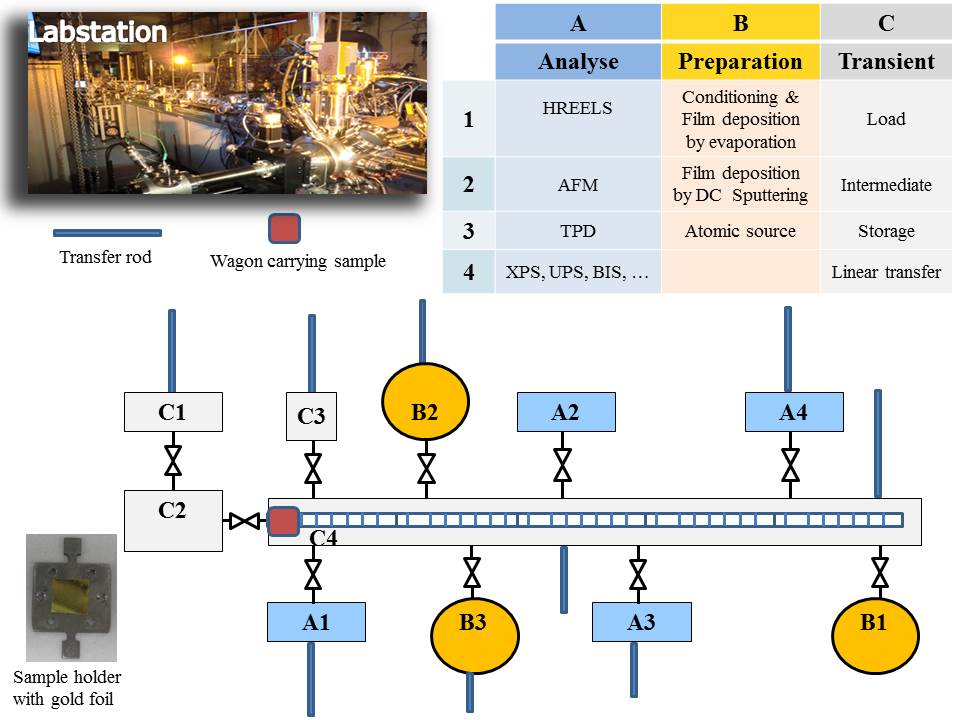
The method reported here allows in situ preparation of a very thin layer (some tens of atomic layers deposited on an inert substrate) and analysis of its surface without contact with the atmosphere. This is one of the advantages of the Labstation (Figure 1), which is a modular machine composed of different chambers kept under dynamic ultra-high vacuum (UHV), reaching pressures of 10-9-10-11 mbar. Chambers are dedicated to preparation of the thin films, surface treatment (gas adsorptions), and characterisation by surface spectroscopies techniques [e.g., x-ray photoelectron spectroscopy (XPS), ultra-violet photoelectron spectroscopy (UPS), low energy electron diffraction spectroscopy (LEED)]. Samples are mounted on specific sample holders and transferred between different chambers through a linear transfer chamber using a transport wagon. All chambers are connected to this central chamber through a valve so they can be isolated at any moment (e.g., for gas filling or servicing). Recuperation of the sample holder/sample from the linear transfer chamber is accomplished by a transfer rod mounted on each chamber. The Labstation base system has been manufactured by an external company (see Table of Materials). Extensions and modifications have been added afterwards depending on experimental requirements, resulting in a unique equipment at JRC Karlsruhe. Extensions include the sputter source (a core element for thin film preparation), which has been developed in-house along with the sputter and data acquisition programs. The loading of the sample holder/sample from an ambient atmosphere to ultra-high vacuum is done via a load lock chamber specially designed to perform multiple sample handling and minimize the time to reaching the final pressure of about 10-8-10-9 mbar, thus limiting air contamination of the system. The Labstation is the result of years of experience and expertise in the surface science field at JRC Karlsruhe.
To pass from one chamber to another, the sample is mounted on a transport wagon driven by an external magnet, controlled by a computer program (Figure 2) and moving along the linear transfer chamber of about 7 m to predefined stop positions in front of the chambers.
Without a similar or close installation, the experiment might be difficult to reproduce. However, this installation contributes to the PAMEC laboratory that contributes to the open access program at JRC, in which external users are invited to submit proposals reviewed by a panel of international scientific experts. Their evaluation then allows users to access the infrastructure operated by the JRC. After requests and in the frame of collaborations, thin films can be prepared for external users for analyses and experiments performed outside JRC Karlsruhe.
In this report, we provide a detailed protocol of the growth of single-valence U2O5 thin films, obtained by successive steps involving oxidation and reduction of UO2 with atomic oxygen and atomic hydrogen, respectively. Unlike UO2 and UO2+x, direct deposition of U2O5 and UO3 films by DC sputtering cannot be done. Therefore, we first proceed to the deposition of a UO2 film, oxidize it into UO3 using atomic oxygen, then reduce it back to U2O5 with atomic hydrogen. The oxidation and reduction times and sample temperature during the process have effects on the result and are important to master. Correct composition was verified with high-resolution X-ray photoelectron spectroscopy, which provides direct and quantitative evidence for uranium 5f1 electronic configuration, as expected for the U(V).
Protocol
1. Sample Holder Preparation
NOTE: Handling of the sample holder outside of the Labstation under an ambient atmosphere should be performed with gloves and clean tweezers.
- Sample holder preparation and ex situ cleaning
- Clean a gold (Au) foil (0.025 mm thickness, 99.99%, see Table of Materials) of size 8 x 8 mm with acetone. Place the foil on a stainless steel or molybdenum holder specifically designed for the Labstation and fix the foil on the holder by spot welding tantalum wires.
- Clean the sample holder and foil again with acetone and let it dry under ambient atmosphere before introduction to the Labstation.
NOTE: A photo of the sample holder with a gold foil is displayed in the inset of Figure 1.
- Introduction of the sample holder to the Labstation
- Close the UHV valve between the load lock chamber and garage chamber (C1/C2). Untighten the screw, fixing the door of C1, and open the nitrogen valve to bring the pressure to atmospheric pressure, enabling opening of the door.
- Introduce the sample holder to C1. Close the door of C1 and open the valve for the primary vacuum.
- Close the valve to the primary pump once the primary vacuum reaches a pressure of about 1 mbar. Open the valve linked to the UHV turbomolecular pump immediately afterwards.Wait until the pressure reaches 10-7 mbar.
NOTE: This last step can take a minimum of 1 to 3 h, depending on sample outgassing.
- Transfer to the preparation chamber (B1)
- Move the transport wagon from the transfer chamber to the intermediate chamber and close the valve between C2 and C3. Open the valve located between C1 and C2. Use the transfer rod of C1 to transfer the sample holder to C2.
NOTE: C2 is an intermediate chamber between C1 and the linear transfer chamber common to all chambers of the Labstation. It separates the load lock chamber, which has a poor vacuum (10-7 mbar) from the rest of the system (around 10-9 mbar). Sample transfers can be rapidly performed at a relatively poor vacuum in the load lock while keeping the Labstation clean. - After the sample holder sits on the wagon in C2, bring back the transfer rod to C1 and close the valve between C1 and C2. Open the valve between C2 and the linear transfer chamber C3.
- Position the wagon in the linear transfer chamber and connect it to the driving magnet before closing the valve between C2 and C3.
- Use the program Linear Transfer Control (LTC, Figure 2) to transfer the wagon to the position of the preparation chamber B1.
- Open the valve between the linear transfer chamber and the preparation chamber B1. Use the transfer rod to position the sample in the preparation chamber B1. Once the transfer rod is back to its initial position, close the valve between the linear transfer chamber and preparation chamber B1.
- Move the transport wagon from the transfer chamber to the intermediate chamber and close the valve between C2 and C3. Open the valve located between C1 and C2. Use the transfer rod of C1 to transfer the sample holder to C2.
- In situ cleaning of the sample holder
- Open the argon valve to reach a pressure of 5 x 10⁻⁵ mbar.
- Position the sample holder surface in the vertical to face the ion gun (IG10/35, see Table of Materials).
- Switch on the ion gun to start Ar ion sputtering (2 keV, 10 mA emission current) and keep cleaning for 10 min. Switch off the ion gun.
- Bring the thermocouple in contact with the sample holder, then switch on the e-beam heater to anneal the sample at 773 K for 5 min. After an initial rise (into the 10-7 mbar range), the pressure falls back to about 10-8 mbar, indicating outgassing completion. Switch off the e-beam heater and let the sample cool down to room temperature (RT).
- Open the valve between the preparation chamber B1 and linear transfer chamber, then position the sample holder on the wagon using the transfer rod. Close the valve of the B1 chamber.
- Sample holder characterization
NOTE: High-resolution X-ray photoelectron spectroscopy (XPS) measurements were performed using a hemispherical analyser (see Table of Materials). A micro-focus source (see Table of Materials) equipped with a monochromator and operating at 120 W was used to produce a radiation of Al Kα (E = 1,486.6 eV). Calibration of the spectrometer was done using the 4f7/2 line of an Au metal, producing a value of 83.9(1) eV binding energy (BE), and the 2p3/2 line of a Cu metal at 932.7(1) eV BE.- Transfer the wagon by remote control using the LTC program to the position of the analysis chamber A4.
NOTE: The background pressure in the analysis chamber is 2 x 10⁻¹⁰ mbar. - Open the valve of the analyses chamber A4 and use the transfer rod to take the sample from the linear transfer chamber to analyses chamber A4. Close the valve of the analysis chamber A4.
- Transfer the sample to the analysis position using the acquisition program (Figure 3).
- Switch on the cooling water and X-ray source of the spectrophotometer (anode voltage = 15 keV, emission current = 120 mA).
- Start the data acquisition using the acquisition program (Figure 3).
NOTE: Optimization of the sample position can be performed with the acquisition program to obtain maximal signal intensity.
NOTE: Photoemission spectra were taken from the sample surface kept at RT. - Start the measurement of an overview spectrum using the following parameters: KEini = 100 eV, KEfin = 1,500 eV, scan time = 300 s, N° of points = 1,401, pass energy = 50 eV, slit = 7 x 20 mm diameter,mode = 1.5 keV/medium area mode.
NOTE: The absence of a C1s peak at about 284.5 eV BE indicates that the surface is clean. - Start the acquisition of Au4f core level spectrum with the following parameters: KEini = 1,396.6 eV, KEfin = 1,406.6 eV, scan time = 60 s, number of points = 201, pass energy = 30 eV, slit = 6 mm diameter, mode = 1.5 keV/medium area mode.
NOTE: This latter measurement will be compared to the spectrum after deposition of the UO2 film on the gold foil to evaluate corresponding thickness of the film. - Once the surface of the sample holder (Au foil) has been analyzed, open the valve of the analysis chamber A4 to position the sample holder on the wagon in the linear transfer chamber using the transfer rod.
- Transfer the wagon by remote control using the LTC program to the position of the analysis chamber A4.
2. Thin Film Preparation
NOTE: Uranium oxide thin films are prepared in situ by direct current (DC) sputtering using a uranium metal target and gas mixture of Ar (6 N) and O2 (4.5 N) partial pressure.
- Deposition of UO2 film
- Transfer the wagon carrying the sample holder to the position of the preparation chamber B2 by remote control using the LTC program.
- Open the valve of the preparation chamber B2, and with the transfer rod, position the sample holder under the sputter source, located in the middle of B2.
NOTE: Before the sputtering process, ensure that the shutter of the sputter source is closed. - Close the valve to isolate the B2 chamber from the linear transfer chamber. Then, open the O2 valve and adjust the oxygen partial pressure to 2.5 x 10⁻⁵ mbar. Open the argon valve gas to reach a partial pressure of 5 x 10⁻³ mbar.
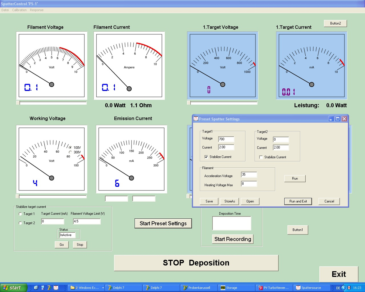
- Use the sputtering program (Figure 4) to enter the following parameters: deposition time = 300 s, uranium target voltage = -700 V, uranium target current = 2 mA, filament heating = 3.3 V/3.9 A, filament working voltage = 40 V.
NOTE: Wait for about 120 s of sputtering with the closed shutter of the sputter source. - Start the timer immediately after opening the shutter of the sputter source to allow deposition of UO2 on the Au foil.
NOTE: To work at low Ar pressure without stabilizing magnetic fields, injections of 25-50 eV energy (triode setup) were enabled to maintain the plasma in the diode. - Stop the sputtering after 300 s, using the corresponding program, and close the Ar and O2 gas valves.
NOTE: The blue light of the plasma will disappear and all sputtering parameters will fall to zero.
NOTE: Wait until the pressure of the preparation chamber B2 reaches 10-8 mbar. - Bring the sample in preparation chamber B1, and for a smooth annealing of the sample, switch on the e-beam heater and set the temperature to 573 K.
NOTE: Wait for 3 to 5 min before stopping the heating.
- UO2 sample characterisation
NOTE: For characterisation of the sample by XPS, the same procedure described for the sample holder characterisation should be followed.- Open the valve between the preparation chamber B1 and linear transfer chamber to transfer the sample to the wagon using the transfer rod. Set the transfer rod back to the preparation chamber B1, then close the valve to isolate it from the linear transfer chamber.
- Follow the same procedure described in steps 1.5.1 to 1.5.6.
NOTE: The overview spectrum enables control of the quality of the UO2 film by excluding additional impurity peaks (C1s, cross-contamination from the sputter source housing) and controlling (roughly) the U:O ratio of the film. - Start acquisition of the Au4f core level (similar parameters as in step 1.5.7).
- Proceed to the acquisition of U4f, O1s, and valence band (VB) using the following parameters:pass energy = 30 eV, slit = 7 x 20 mm diameter, mode = 1.5 keV, medium area.
U4f: KEini = 1,066.6 eV KEfin = 1,126.6 eV Scan time = 300 s N° of points = 601
O1s: KEini = 946.6 eV KEfin = 966.6 eV Scan time = 300 s N° of points = 201
Vb: KEini = 1,473.6 eV KEfin = 1,488.6 eV Scan time = 1,800 s N° of points = 601
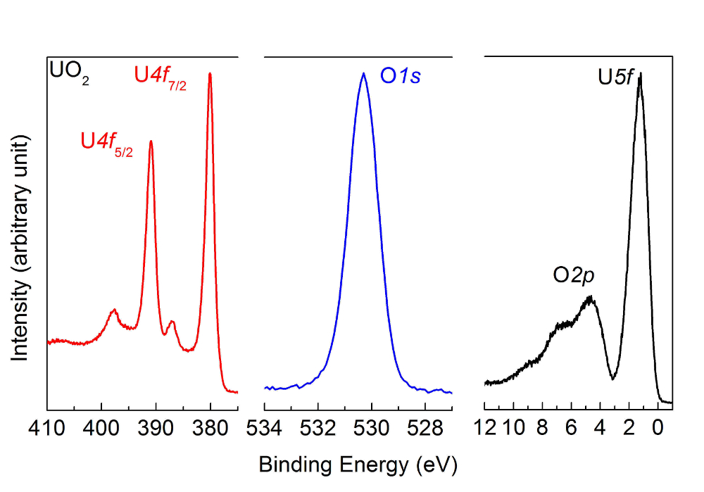
NOTE: The obtained spectra for the UO2 film are reported in Figure 5.
- Oxidation of UO2 with atomic oxygen
NOTE: The atom flux (see Table of Materials) is specified to >1016 atoms/cm2/s, corresponding to an exposure up to 20 s of roughly 10 Langmuirs (i.e., 1.33 x 10⁻³ Pa•s).- Transfer the wagon carrying the sample to the preparation chamber B3. Open the valve of the preparation chamber B3, and with the transfer rod, position the sample inside B3 in front of the atom source. Close the valve to isolate the chamber from the linear transfer chamber.
- Set the sample temperature to 573 K. Wait 5 min to allow the sample to reach the holder's temperature.
- Open the oxygen valve and set the partial pressure to 1.2 x 10⁻⁵ mbar O2. Switch on the cooling water for the atom source.
- Switch on the atomic source and set the current to 20 mA. Pay attention to the exact time to oxidize the sample with the atomic source. If oxidation time is too short, the oxidation to UO3 can be incomplete as reported in Figure 6.
- Wait 20 min to achieve complete oxidation of UO2 into UO3 and switch off the atomic source before closing the oxygen valve. Once the pressure of the preparation chamber B3 is 10-7 mbar, open the valve to transfer the sample to the wagon present in the linear transfer chamber. Then, close the valve of the preparation chamber B3.
- Analysis of UO3 obtained after oxidation of UO2 with atomic oxygen
- Transfer the sample to the analyses chamber following steps 1.5.1 to 1.5.6; then, for the analyses, follow the same procedure as described in step 2.2.4.
NOTE: The corresponding spectra of UO3 are reported in Figure 7.
- Transfer the sample to the analyses chamber following steps 1.5.1 to 1.5.6; then, for the analyses, follow the same procedure as described in step 2.2.4.
- Reduction of UO3 by atomic hydrogen
- To transfer the sample to the preparation chamber B3, follow steps 2.3.1 and 2.3.2.
- Open the hydrogen valve and set the partial pressure to 3 x 10⁻⁵ mbar. Switch on the cooling water for the atom source. Switch on the atomic source and set the current to 30 mA.
- Wait for 60 s of reduction time before switching off the atomic source. Pay attention to the exact time taken to reduce the sample with the atomic source. If reduction time is too long, then UO2+x is further reduced to UO2 as reported in Figure 8. If this occurs, the sample must be oxidized again with atomic oxygen (as we did to get UO3), whose corresponding spectra are reported in Figure 9.
- Analysis of U2O5 obtained after reduction of UO3 with atomic hydrogen
- Transfer the sample to the analysis chamber following steps 1.5.1 to 1.5.6; then, for the analyses, follow the same procedure as described in step 2.2.4.
NOTE: The obtained spectra of U4f, O1s, and the VB are reported in Figure 10. As an example of incomplete reduction to U2O5, similar spectra as shown in Figure 6 are obtained.
- Transfer the sample to the analysis chamber following steps 1.5.1 to 1.5.6; then, for the analyses, follow the same procedure as described in step 2.2.4.
Results
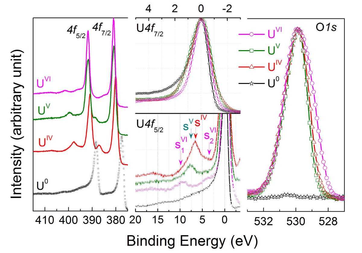
The identification of U(V) can be easily done by a characteristic energy of the shake-up satellite accompanying the characteristic U4f doublet. The binding energy at which appears the satellite, associated with intrinsic energy loss processes, depends on the uranium oxidation state.
Uranium 4f core level X-ray photoemission spectra are recorded for U(IV) in UO2 (red curve), U(V) in U2O5 (green curve), and U(VI) in UO3 (pink curve), then compared to U(0) in uranium metal (black curve) in the left part of Figure 11. The corresponding O1s core level spectra are superposed and reported in the right part of Figure 11.
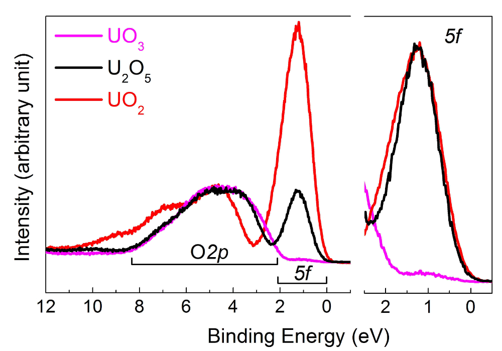
In the center part of Figure 11, the U4f7/2 core level peaks have been shifted to superpose the main lines (upper half), allowing visualization of the energy separation (ΔE) between the satellite and main line (lower half). With increasing oxidation state, the energy separation increases, while satellite intensity decreases. Spectra were obtained on thin films of about 20 monolayers in thickness. The satellite energy peak and the 4f5/2 (4f7/2) emission line were used as a fingerprint for the oxidation state of the uranium atoms. The valence band spectra of UO2, U2O5, and UO3 obtained on the same films are reported in Figure 12.
The spectra described in the protocol are corresponding to UO2 films (Figure 5) obtained after deposition in the preparation chamber B2. This film is then oxidized with atomic oxygen. Depending on the oxidation time, the result can be UO2+x (as reported in Figure 6) or UO3 (as reported in Figure 7). Also, if atomic reduction with hydrogen on UO3 is too long, it will return to UO2 as reported in Figure 8. In this case, reoxidation to UO3 as reported in Figure 9 should take place before reducing it again with an appropriate time to get U2O5, as displayed in Figure 10. The results show that the oxidation and reduction processes are completely reversible.

Figure 1: Photograph and schematic of the Labstation machine developed at JRC Karlsruhe to enable in situ surface science studies. Please click here to view a larger version of this figure.

Figure 2: Screenshot of the linear transfer control program. The program enables transfer of the wagon carrying the samples (I to V) along the linear transfer chamber at different chamber positions. Please click here to view a larger version of this figure.

Figure 3: Screenshot of the acquisition program. Once the measurement conditions are introduced, a series of measurements can be performed automatically after switching on the X-ray generator. The sample position window enables positioning of the sample in the analyses chamber. The adjustment along x, y, and z can be done to optimize the intensity of the signal. Please click here to view a larger version of this figure.

Figure 4: Screenshot of the sputter control program. The sputtering conditions can be selected with this program developed in-house. Among the variables to be defined are the heating and working voltages of the filament and the voltages of up to two targets. Please click here to view a larger version of this figure.

Figure 5: U4f, O1s, and valence band spectra after deposition of a UO2 film, measured by high-resolution X-ray photoemission spectroscopy. The peak and satellite positions are characteristic of a UO2 sample. Please click here to view a larger version of this figure.

Figure 6: U4f, O1s, and valence band spectra after oxidation of UO2 with atomic oxygen, measured by high-resolution X-ray photoemission spectroscopy. The oxidation time is too short, thus the oxidation to UO3 is incomplete. The satellite and peak positions are characteristic of UO2+x and not of the UO3 reported in Figure 7. Please click here to view a larger version of this figure.

Figure 7: U4f, O1s, and valence band spectra measured after oxidation of UO2 film with atomic oxygen using high-resolution X-ray photoemission spectroscopy. The peak and satellite positions are characteristic of a UO3 sample. Please click here to view a larger version of this figure.

Figure 8: U4f, O1s, and valence band spectra measured after reduction of UO3 with atomic hydrogen. The reduction time is too long, thus the U2O5 is further reduced to UO2. The satellite and peak positions are characteristic of a UO2 and not the U2O5 sample reported in Figure 10. Please click here to view a larger version of this figure.

Figure 9: U4f, O1s, and valence band of the sample obtained in Figure 8 and re-oxidized with atomic oxygen to UO3. The satellite and peak positions are characteristic of a UO3 sample. The processes of reduction and oxidation are thus reversible. Please click here to view a larger version of this figure.

Figure 10: U4f, O1s, and valence band spectra after reduction of UO3 film with atomic hydrogen, measured by high-resolution X-ray photoemission spectroscopy. The peak and satellite positions are characteristic of a U2O5 sample. Please click here to view a larger version of this figure.

Figure 11: U4f and O1s core level X-ray photoemission spectra of U(IV) in UO2 (red curve), U(V) in U2O5 (green curve), and U(VI) in UO3 (pink curve), then compared to U(0) in uranium metal (black curve). Please click here to view a larger version of this figure.

Figure 12: Valence band spectra of U(IV) in UO2 (red curve), U(V) in U2O5 (black curve), and U(VI) in UO3 (pink curve). Please click here to view a larger version of this figure.
Discussion
The initial results obtained on the thin films of U2O5 of about 30 monolayers (ML) in thickness, together with the corresponding core level spectroscopy obtained with high-resolution X-ray photoemission spectroscopy, have been reported in a previous publication7. The evolution of the uranium state during the oxidation process of UO2 into UO3 was reported through X-ray photoelectron spectra obtained on thin films of two to 50 layers in thickness in a wide range of the O:U ratio (Figure 11, Figure 12). Film oxidation and film reduction were obtained by exposing the films to atomic oxygen and atomic hydrogen, respectively. The homogeneity of the films with uranium oxidation states from IV to VI could be confirmed due to their small thickness and the reaction temperatures. Thin films of uranium oxides are deposited on a substrate using direct current sputtering with a sputter source developed at JRC Karlsruhe. The sputter source is installed in a chamber kept under ultra-high vacuum, like all the chambers of the Labstation. While UO2 can be obtained directly, UO3 and U2O5 films are only obtained after further treatment with atomic oxygen and atomic hydrogen. The binding energy of the main peaks and their satellites positions allow differentiation between the oxidation states of uranium in uranium oxide films produced in situ. High-resolution spectroscopy is necessary to differentiate the different oxidation states, as the satellite binding energies are close and have low intensities.
In 1948, pure pentavalent uranium, U2O5, was identified for the first time8. Later, its synthesis was described based on high temperature (673-1,073 K) and high pressure (30-60 kbar) of a mixture of UO2 and U3O89. However, the existence and stability of U2O5 at ambient temperature and pressure conditions have been questioned, suggesting a lower limit of x = 0.56-0.6 for the single-phase region below U3O810. So far, preparation of U2O5 at high pressure and temperature or during a thermo-reduction process was not reproducible; often, it was not possible to assign a single oxidation state to obtained samples. Some of a U2O5 bulk sample preparation appeared as mixtures of UO2 or UO3 with coexistence of U(V) with U(IV) or U(VI), as for U4O9 and U3O8. For instance, Teterin et al.11 reported the leaching process of U3O8 in sulphuric acid followed by thermal treatment in a helium atmosphere, claiming that the results were related to U2O5. This conclusion could be easily excluded due to a resulting two-peak structure in their XPS spectra. A mixture of U(V) and U(VI) species could explain the result, excluding the formation of a single U(V) oxidation state expected for U2O5.
Our method of preparation allows preparation of thin films of uranium oxide with single oxidation states of U(IV), U(VI), and U(V). The entire process of sample preparation takes place in situ within an instrument maintained at ultra-high vacuum. It was found that reduction of UO3 by atomic hydrogen does not proceed to UO2 but can be stopped at U(V). The time factor is very important as well as the temperature of the sample during the reduction process. With the high-resolution photoemission spectrometer, it was shown that a pure sample of U2O5 can be prepared in situ. Preparing thicker films should be a next step in looking at the crystallographic structure and bulk properties with ex situ techniques.
Disclosures
The authors have nothing to disclose.
Acknowledgements
The authors have no acknowledgements.
Materials
| Name | Company | Catalog Number | Comments |
| 1ary dry scroll vacuum pump | Agilent | SH-100 | All chambers except B1 |
| 1ary pump | EDWARDS | nXDS10i 100/240V | B1 chamber |
| Acetone | |||
| Acquisition programme | Developed in-house | ||
| Analyser | Specs | Phoibos 150 hemispherical | A4 chamber |
| Argon | BASI | 6N | |
| Atomic source | GenII plasma source | Tectra | B3 chamber |
| Au foil | Goodfellow | ||
| CasaXPS programme | CasaXPS | ||
| Gauge 1ary vacuum | PFEIFFER | TPR 280 (2011/10) | All chambers |
| Gauge 2ary vacuum | VACOM | ATMION ATS40C | All chambers |
| Hydrogen gas | BASI | 6N | |
| Ion gun source | Specs | IG10/35 | B1 chamber |
| Linear transfer programme | Specs | Program delivered with the station | |
| Origin programme | Origin | OriginPro 8.1SRO | |
| Oxygen gas | 6N | ||
| Sampler e-beam heater power supply | Specs | SH100 | B1 chamber |
| Sampler resistance heater | Made in-house | power supply + Eurotherm | B3 chamber |
| Sputtering programme | Developed in-house | ||
| Stainless steal or Molybdenum substrate | in house | ||
| Ta wire | Goodfellow | ||
| turbo pump | PFEIFFER | TC 400 | All chambers |
| Uranium target | in house | in house | Natural uranium target |
| Vacuum gauge controller | VACOM | MVC-3 | All chambers |
| X-ray source | Specs | XRC-1000 MF | Equipped with a monochromator |
References
- Shoesmith, D. W., Sunder, S., Hocking, W. H., Lipkowski, J., Ross, P. N. Electrochemistry of UO2 nuclear fuel. Electrochemistry of Novel Materials. , (1994).
- Shoesmith, D. W. Fuel corrosion processes under waste disposal conditions. Journal of Nuclear Matter. 282, 1-31 (2000).
- Gouder, T., Shick, A. B., Huber, F. Surface interaction of PuO2, UO2+x and UO3 with water ice. Topics in Catalysis. 56, 1112-1120 (2013).
- Cohen, C., et al. Water chemisorption on a sputter deposited uranium dioxide film - Effect of defects. Solid State Ionics. 263, 39-45 (2014).
- Seibert, A., et al. The use of the electrochemical quartz crystal microbalance (EQCM) in corrosion studies of UO2 thin film models. Journal of Nuclear Matter. 419, 112-121 (2011).
- Majumder, I., et al. Syntheses of U3O8 nanoparticles form four different uranyl complexes: Their catalytic performance for various alcohol oxidations. Inorganic Chimica Acta. 462, 112-122 (2017).
- Gouder, T., et al. Direct observation of pure pentavalent uranium in U2O5 thin films by high-resolution photoemission spectroscopy. Scientific Reports. 8, 1-7 (2018).
- Rundle, R. E., Baeziger, N. C., Wilson, A. S., MacDonald, R. A. The structures of the carbides, nitrides and oxides of uranium. Journal of the American Chemical Society. 70, 99 (1948).
- Hoekstra, H. R., Siegel, S., Gallagher, F. X. The uranium-oxygen system at high pressure. Journal of Inorganic and Nuclear Chemistry. 32, 3237 (1970).
- Kovba, L. M., Komarevtseva, N. I., Kuz'mitcheva, E. U. On the crystal structures of U13O34 and delta-U2O5. Radiokhimiya. 21, 754 (1979).
- Teterin, Y. A., et al. A study of synthetic and natural uranium oxides by X-ray photoelectron spectroscopy. Physics and Chemistry of Minerals. 7, 151-158 (1981).
Reprints and Permissions
Request permission to reuse the text or figures of this JoVE article
Request PermissionThis article has been published
Video Coming Soon
Copyright © 2025 MyJoVE Corporation. All rights reserved