A Microfluidic Approach for the Study of Ice and Clathrate Hydrate Crystallization
In This Article
Summary
The present protocol describes the crystallization of microscopic ice crystals and clathrate hydrates in microfluidic devices, enabling liquid exchange around the formed crystals. This provides unparalleled possibilities to examine the crystallization process and binding mechanisms of the inhibitors.
Abstract
An accurate mechanistic description of water crystallization is challenging and requires a few key elements: superb temperature control to allow the formation of single microscopic crystals and a suitable microscopy system coupled to the cold stage. The method described herein adds another important feature that includes exchanging solutions around ice and clathrate hydrate crystals. The described system comprises a combination of unique and home-developed instruments, including microfluidics, high-resolution cold stages, and fluorescence microscopy. The cold stage was designed for microfluidic devices and allows for the formation of micron-sized ice/hydrate crystals inside microfluidic channels and the exchange of solutions around them. The temperature resolution and stability of the cold stage is one millikelvin, which is crucial for controlling the growth of these small crystals. This diverse system is used to study the different processes of ice and hydrate crystallization and the mechanism by which the growth of these crystals is inhibited. The protocol describes how to prepare microfluidic devices, how to grow and control microscopic crystals in the microfluidic channels, and how the utilization of the flow of liquids around ice/hydrate crystals affords new insights into the crystallization of water.
Introduction
Antifreeze proteins (AFPs) and antifreeze glycoproteins (AFGPs) protect various cold-adapted organisms from frost damages1. AFPs and AFGPs (generalized as AF(G)Ps) inhibit the growth of ice crystals by binding irreversibly to their surfaces and inhibiting further growth due to the Gibbs-Thomson effect2,3,4,5. The resulting gap that forms between the melting temperature, which is largely unchanged, and the newly depressed freezing temperature is called thermal hysteresis (TH) and represents a measurable parameter corresponding to AFP activity6. The use of AFPs to inhibit ice growth has far-reaching and diverse applications, offering potential enhancement in various fields, including cryopreservation, frozen food quality, and protection of cold-exposed crops.
The crystallization of water at low temperatures and high pressures in the presence of small organic molecules results in the formation of clathrate hydrates (or gas hydrates), where the most abundant hydrate is methane hydrate7. The crystallization of methane hydrates in gas/oil flowlines may cause plugs, which might cause explosions due to gas ignition8,9,10. Current efforts to prevent hydrate crystallization in flowlines include using thermodynamic (alcohols and glycols) and kinetic (mainly polymers) inhibitors11,12,13,14. AFPs have also been found to bind to clathrate hydrate crystals and inhibit their growth, which points to the potential use of AFPs to hinder the formation of plugs, thereby providing a greener solution15.
Microfluidics is a prevalent method used to study the properties of fluids at minuscule sample volumes (down to fL) that are flowed through a network of microchannels16. The microchannels follow a pattern created on a silicon wafer (the mold) using lithography17. A commonly used material to fabricate microfluidic devices is polydimethylsiloxane (PDMS), which is inexpensive and relatively simple to work with in research laboratories. The design of the features (channels) is composed with regard to the specific purpose of the device; thus, it can be utilized for a variety of applications, including DNA sensing18, medical diagnosis19 and crystallization processes3,20,21.
The present protocol describes a unique microfluidic method of growing micron-sized ice and hydrate crystals with various inhibitors, including AFPs and AFGPs. For these experiments, Tetrahydrofuran (THF) hydrates were used to mimic the properties of methane gas hydrates22, which require specialized equipment for pressure and temperature control23. Fluorescently labeled AF(G)Ps were used to visualize and analyze the adsorption of the proteins to the crystal surface, and coupled with fluorescent imaging, the microfluidic approach allowed the obtaining of key features of the binding process of these molecules to crystal surfaces.
Protocol
1. Microfluidic device fabrication
- Cover the inside surface of a Petri dish with aluminum foil and place the pre-prepared mold into the Petri dish.
- Fabricate the molds using the lithography techniques described in references. The two device designs used in the present work are depicted in Figure 1.
- Prepare 30-40 mL of the PDMS mixture by weighing a 1:10 (by weight) mixture of the curing agent and elastomer (see Table of Materials) and mixing continuously for approximately 5 min until the mixture appears white and nearly opaque.
NOTE: Place a plastic cup on the weighing scale, pour the elastomer into the cup, and then add the curing agent to achieve a 1:10 weight ratio. - Pour the PDMS mixture into the Petri dish with the mold and degas in a desiccator until no bubbles remain (approximately 30 min).
- Bake the mold with the liquid PDMS in an oven or on a hot plate at 70 °C until a rubber-like consistency is obtained. This process takes about an hour.
- Cut the device out by tracing around the features with a scalpel, taking care to push forward with the scalpel instead of down since the mold is fragile. Remove the cut-out PDMS device, placing it upside-down in a new Petri dish. Remove dust and dirt particles from the bottom surface by attaching and removing a piece of adhesive tape (see Table of Materials).
- Use a blunt syringe needle (20 G) to punch out holes in the device based on the imprinted pattern, using a microscope if necessary. Ensure that the hole penetrates through the other side of the device, and use tweezers to remove the punched-out pieces.
- Thoroughly wash a coverslip (18 x 18 mm, 0.14 mm thick) with water and soap, and then with isopropanol. Use air pressure to dry the cleaned coverslip.
- Insert the cleaned PDMS and coverslip into the plasma cleaner, close the valves, and turn on the power, vacuum, and pump. Allow the plasma cleaner to run for about a minute, set the RF to HI, and allow some air to enter the plasma cleaner using the fine valve.
- When the viewing window's color changes from purple to pink, let the plasma cleaner work for 50 s and turn the RF off. Keep the pump on for a minute, and after turning it off, gradually open the main valve to allow air into the plasma cleaner.
NOTE: An alternative method to achieve comparable results is heat bonding. For this method, lay the mold onto the coverslip and place it on a hot plate set to 70-80 °C for approximately 60 min.
- When the viewing window's color changes from purple to pink, let the plasma cleaner work for 50 s and turn the RF off. Keep the pump on for a minute, and after turning it off, gradually open the main valve to allow air into the plasma cleaner.
- Press the PDMS surface onto the cleaned coverslip and confirm that they are bonded by observing no detachment when pulling up slightly on the coverslip.
- Secure the needle of a 90° blunt needle (18 G) with a pair of pliers and pull off the plastic syringe connector to remove it. Insert one end of the needle into a Tygon tube (0.020" ID, 0.060" OD, see Table of Materials) and the other end into one of the punched-out holes of the device. Repeat the process for the other holes.
- To remove air bubbles, inject water/buffer into the channels with a glass syringe (a pump is optional, but no pump was used here). Filter all liquids with a 0.22 µm filter before injecting them into the device.
- Use a blocking agent such as a 1% BSA solution to prevent the binding of fluorescence-labeled AFPs onto the PDMS walls. Inject the blocking agent into the inlet channel and allow it to remain in the microchannels for 20 min. Then, inject the buffer solution into the inlet channel to flush out the BSA solution.
NOTE: The resulting PDMS device is attached to a coverslip along its bottom surface, connected to tubing in its inlet and outlet holes, and coated with a blocking agent in its channels.
2. Setting up the microfluidic device
- Apply a small amount of immersion oil to the surface of the copper cold stage (see Table of Materials) and spread it using a lint-free wipe to create a thin layer of oil. Next, place a clean sapphire disc (see Table of Materials) on the created oil layer. Apply a droplet of immersion oil onto the center of the sapphire disc and position the PDMS device onto the drop such that the features of the device are aligned over the viewing hole of the cold stage.
- Hold the device in place and secure the tubing to the outer walls of the aluminium box that houses the cold stage using adhesive tape. Make a note of the placement of each specific tube.
- Use a glass syringe to inject 4-5 µL of AF(G)P solution (see Table of Materials) into the inlet channel. Close the lid of the cold stage.
NOTE: The concentration of the AFP solutions can be varied and decided based on their fluorescence intensity. In the present protocol, the range of concentrations was 5-40 µL.
3. Formation of single crystals in the microfluidic channels
- Purge the cold stage with dry air/nitrogen to prevent condensation from forming inside it. Activate a circulating cooling bath to circulate water through the cold stage and serve as a heat sink.
- Initiate the temperature control program and set the temperature to -25 °C.
NOTE: Freezing will occur as the sample reaches a temperature of ~-20 °C, which can be observed as a sudden darkening and roughening of the sample. Any objective can be used at this point, preferably the 4x objective, which enables the user to observe the entirety of the microfluidic channels. - Slowly, increasing the temperature by approximately 1 °C/5 s, approach the sample's melting point, which can range from -1 to -0.2 °C depending on the buffer used in the AF(G)P solution. As the temperature approaches the melting point, wait until a few single crystals are isolated.
NOTE: If needed, unwanted ice can be locally melted using an IR laser (980 nm) (see Table of Materials), which is fixed on the microscope. The laser melts nearby ice crystals as long as it is on. - At this point, it is recommended to switch to 10x or 20x objectives to better observe single crystals. After obtaining a single crystal in the desired location, grow the crystal by slightly decreasing the temperature (by ~0.01 °C) until the edges of the crystal meet the channel walls.
- Switch to the 50x objective, inject the AF(G)P solution into the channels, and observe the fluorescence intensity increase, indicating that the protein solution was successfully injected into the channels. Perform this step carefully to avoid melting of the ice crystal during the exchange of solutions. Closely monitor and adjust both the flow rate (by applying more/less pressure on the glass syringe) and the temperature during the solution exchange process.
- Allow the proteins enough time to accumulate and bind onto the crystal surface.
NOTE: This varies based on the accumulation and adsorption rates of the AF(G)P5,25. In a typical experiment, 5-10 min are allowed for AFP accumulation
4. Thermal Hysteresis (TH) activity measurement
NOTE: This step is optional.
- Determine the melting point of the crystal by adjusting the temperature with small steps of 0.002 °C and observing the highest temperature that a small crystal can be subjected to without it melting.
- On the RAMP function of the temperature controller, set the cooling rate to -0.05 to -0.01 °C/4 s and activate the RAMP. Note the exact temperature at which sudden crystal growth occurs.
NOTE: This value is called the burst temperature and corresponds to the temperature of freezing. The difference between the melting and freezing temperatures is the TH activity25.
5. Solution exchange around single crystals
- Ensure that the sample temperature is in the TH gap to prevent the melting or growth of the crystal during the experiment.
- Record the solution exchange process using the NIS Elements imaging program (see Table of Materials) for later fluorescence data analysis. Slowly inject the buffer solution into the second inlet of the microfluidic device, and observe a decrease in the fluorescent signal at a rate that depends on the pressure applied to the syringe.
- Use this visual representation to ensure that the applied pressure is not too high so as not to cause the crystal to melt. See Figure 2 for a sequence of images demonstrating the solution exchange process.
- Measure the fluorescence intensity in the microfluidic channel using the imaging program.
NOTE: The signal should peak at the region near the surface of the crystal, indicating AFP binding, and should be relatively low in the surrounding solution, which has been flushed with buffer. - Measure the TH activity after the solution exchange following step 4.
- Repeat the experiment by isolating a new crystal (steps 3.3-3.5). Inject the AFP solution with a glass syringe and repeat the solution exchange (steps 5.1-5.3). Obtain a new single crystal (steps 3.3-3.5) and flow the AFP solution into the channels using the glass syringe.
6. Experiments with clathrate hydrates
- To obtain THF hydrates, prepare a THF/water solution with a molar ratio of 1:15, which is a volume ratio of 1:3.326. Maintain this ratio in all solutions used in the following experiments, including those containing AF(G)Ps or other inhibitors.
- Follow steps 1 and 2 to prepare the microfluidic device and place it in the cold stage. Set the temperature to -25 °C; the sample will freeze at ~-20 °C as described in step 3.2.
- After the THF solution is frozen, slowly increase the temperature until all the ice has melted.
NOTE: The melting point of ice is slightly depressed by the THF. - To ensure that all the ice crystals melted at the exclusion of the hydrates, hold the temperature at 1 °C for 3 min.
- Set the temperature to -2 °C and observe the abundance of hydrates that appear in the microfluidic channels in the absence of inhibitors.
NOTE: THF hydrates are shaped as octahedrons (Figure 2), and in some cases, the crystals are very thin; thus, clear observation might be challenging. In these cases, it is recommended to repeat steps 6.4-6.5 to obtain new crystals. - Inject the AF(G)P/inhibitor into the microfluidic channel using the glass syringe while adjusting the temperature to ensure that the obtained crystals do not melt/grow. Allow a few minutes for the inhibitor molecules to adsorb to the crystal surface.
- If needed, measure the TH activity following step 4.
- Exchange the solution around the crystals as described in steps 5.2-5.3.
Representative Results
Solution exchange with ice crystals
A successful solution exchange around an ice crystal is presented in Figure 3. The time stamp on each snapshot indicates that the solution exchange was relatively fast; however, a slower exchange is possible. The fluorescence intensity coming from the ice-adsorbed AFGP molecules is clearly observed after the exchange is complete (Figure 3, right). A quantitative analysis of the AFP concentration on the ice surface is monitored using a designated region of interest (ROI) tool (Figure 4). In this experiment4, AFP type III (QAE isoform) diluted in 50 mM Tris-HCl (pH 7.8) and 100 mM NaCl was used. The solution is exchanged around a bipyramidal-shaped crystal, and the fluorescence intensity in the solution and on the ice is monitored. The red plot indicating the fluorescence signal in the solution is decreased by a factor of 100 during the solution exchange, while the calculated signal (green plot) on the ice surface stays constant. The calculated signal of the ice-adsorbed molecules was obtained by subtracting the signal coming from the solution (multiplied by a constant that relates to the thickness of the microfluidic channel) from the signal coming from the ice4.
Solution exchange with THF hydrates
Microfluidic experiments with THF hydrates were carried out similarly to the experiments with ice. After the hydrate crystals were allowed to adsorb the inhibitor molecules from the solution, an inhibitor-free solution was injected into the channels. Figure 5 presents THF hydrates after solution exchange with two types of inhibitors: AFGP1-5 labeled with fluorescein isothiocyanate (FITC) (Figure 5A) and safranine O (see Table of Materials), which is a fluorescence dye26 (Figure 5B). This is the first demonstartion of an AFGP binding to the surface of a clathrate hydrate.
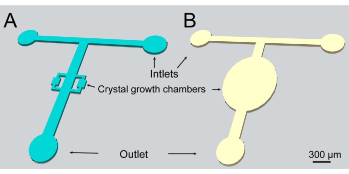
Figure 1: A schematic representation of the microfluidic channels used in the present study. Both designs include two inlets and one outlet. Please click here to view a larger version of this figure.
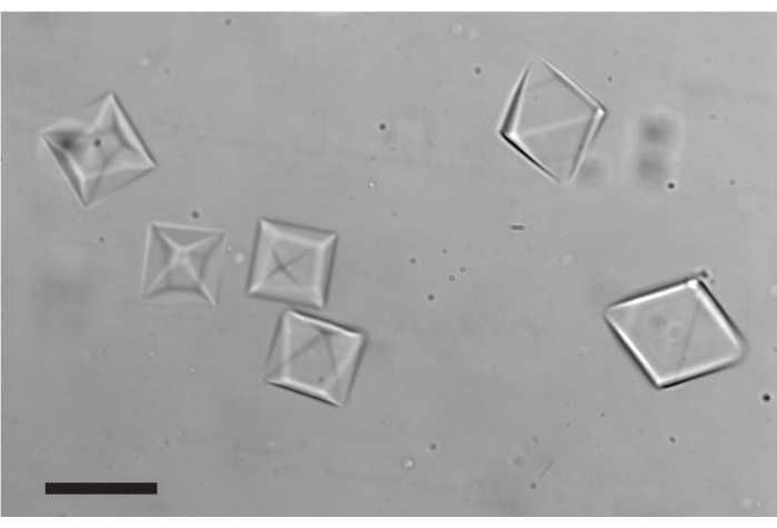
Figure 2: THF hydrates formed in the microfluidic channel after the temperature was cooled to ~-2 °C. The morphology of all crystals presented is a tetrahedron; however, some crystals are oriented differently. Scale bar = 20 µm. Please click here to view a larger version of this figure.
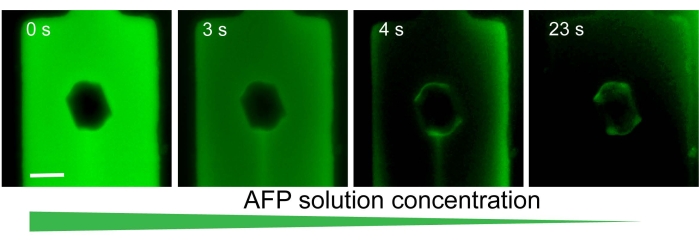
Figure 3: A representative experiment exhibiting solution exchange around a single ice crystal in a microfluidic channel. Initially, the solution contained AFGP1-5 labeled with FITC, and ice-adsorbed AFGPs were not observed. After the solution was exchanged for an AFGP-free solution, the proteins that had been previously adsorbed to the ice surface were clearly detected (image on the right). Scale bar = 25 µm. Please click here to view a larger version of this figure.
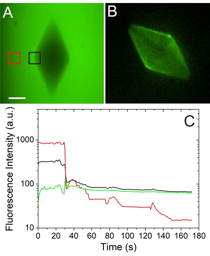
Figure 4: A quantitative and qualitative analysis of the AFP concentration on the ice surface. (A) An ice crystal at high AFP solution concentration (before solution exchange). (B) The same crystal after the AFP solution was exchanged with an AFP-free buffer solution. Scale bar = 20 µm. (C) Quantitative analysis of the fluorescence intensity on the ice surface (black) and in the solution (red) during a solution exchange. The green curve represents the calculated intensity on the ice surface. The figure is adapted with permission from reference4. Please click here to view a larger version of this figure.
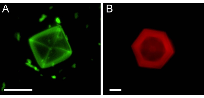
Figure 5: Single THF hydrate crystals in microfluidic channels after the solution around them (A, AFGP1-5) or (B, Safranine O) was exchanged. The image in (B) is reproduced from reference26. Scale bar = 25 µm. Please click here to view a larger version of this figure.
Discussion
The present protocol was designed to utilize the combination of microfluidic flow with microscopic crystals in order to reveal new insights into crystal growth and its inhibition. A millikelvin-resolution temperature-controlled cold stage27 enables the control of single microscopic crystals situated inside microfluidic channels, thereby allowing the exchange of solutions around them. While the fabrication of microfluidic devices is standard and similar to common practices17,18, the control over the growth and melting of crystals inside the device is unique and novel. The most critical component in this system is the superb temperature control, which is achieved by using Peltier thermoelectric coolers, feedback from a thermistor that is located close to the sample, and a high-resolution temperature controller that governs the feedback loop.
Another critical step is the solution exchange itself, as the crystals might melt or grow during this process; thus, the temperature must be adjusted during the solution exchange to prevent growth/melting. The formation of crystals in microfluidic channels interferes with the liquid flow and poses the main challenge of this system; thus, the growth of these crystals must be controlled. Here, an IR laser (980 nm) was mounted on the inverted microscope and was used to locally melt unwanted ice/hydrate crystals28. If such a laser cannot be used, the metallic connectors of the microfluidic device can be heated by an additional Peltier thermoelectric cooler, which will melt the ice in the inlet/outlet of the device.
The method described here includes home-developed instruments (cold stage) and requires training, as some of the abovementioned steps are challenging. As the concentration of the solution surrounding the crystals may change even when the flow is not intended, a simple calibration step5 can provide a reliable estimation of the concentration based on the fluorescence signal. Another possible solution to unwanted flow (during TH measurements, for example) is microfluidic valves, which are described in reference4.
This system was also used to explore the growth behavior of D2O ice in H2O liquid, a study that revealed a new phenomenon of microscopic, scalloped ice surfaces27. Thus, microfluidics can be used in the study of various crystalline systems that respond well to temperature changes.
Acknowledgements
Acknowledgment is made to the Donors of the American Chemical Society Petroleum Research Fund for support of this research (Grant number 60191-UNI5). The authors would like to thank Prof. Ido Braslavsky for pioneering the use of microfluidic devices to study antifreeze proteins and ice. The authors are thankful to Prof. Arthur DeVries, Prof. Konrad Meister and Prof. Peter Davies for providing antifreeze protein samples.
Materials
| Name | Company | Catalog Number | Comments |
| 0.22-micron filters | Fisher Scientific | ||
| 90-degree bent blunt needles | 18 Gauge | ||
| Antifreeze proteins and antifreeze glycoproteins | A gift | See references 5 and 28 | |
| Blunt needles | 18 Gauge and 20 Gauge | ||
| Bovine Serum Albumin (BSA) | Sigma-Aldrich | ||
| Cold stage | Home made | ||
| Cover slips | Globe Scientific | 18 X 18 mm, 0.14 mm thickness | |
| Glass syringe | |||
| Infrared laser 980 nm | Opto Engine LLC | ||
| Inverted microscope, Eclipse Ti - S | Nikon | ||
| Invisible tape | Staples | ||
| lint-free wipe | Kimwipes | ||
| Newport 3040 temperature controller | Newport 3040 | ||
| NIS-Elements Imaging Software | Nikon | ||
| Oil vacuum pump | Harrick Plasma | ||
| Plasma cleaner | Harrick Plasma | PDC-32G | |
| Polydimethylsiloxane (Dow Corning Sylgard 184 Silicone Elastomer kit) | Dow Corning Syglard | ||
| Safranine O | Sigma-Aldrich | S2255-25G | |
| Sapphire disc | Ted Pella Inc | 16005-1010 | 25.4 mm diameter, 0.3 mm thickness |
| sCMOS Camera, Neo 5.5 | Andor | ||
| Tetrahydrofuran (THF) | Sigma-Aldrich | 401757-100ML | |
| Tygon Microbore tubing for microfluidic device | Cole-Parmer | 0.020" ID, 0.060"OD, 100 ft/roll. | |
| Tygon tubing for water circulation and nitrogen gas | Cole-Parmer | 1/8” ID, 3/16” OD |
References
- Bar Dolev, M., Braslavsky, I., Davies, P. L. Ice-Binding Proteins and Their Function. Annual Review of Biochemistry. 85 (1), 515-542 (2016).
- Raymond, J. A., DeVries, A. L. Adsorption inhibition as a mechanism of freezing resistance in polar fishes. Proceedings of the National Academy of Sciences of the United States of America. 74 (6), 2589-2593 (1977).
- Celik, Y., et al. Microfluidic experiments reveal that antifreeze proteins bound to ice crystals suffice to prevent their growth. Proceedings of the National Academy of Sciences of the United States of America. 110 (4), 1309-1314 (2013).
- Drori, R., Davies, P. L., Braslavsky, I. When are antifreeze proteins in solution essential for ice growth inhibition. Langmuir. 31 (21), 5805-5811 (2015).
- Meister, K., DeVries, A. L., Bakker, H. J., Drori, R. Antifreeze glycoproteins bind irreversibly to ice. Journal of the American Chemical Society. 140 (30), 9365-9368 (2018).
- Braslavsky, I., Drori, R. LabVIEW-operated Novel Nanoliter Osmometer for Ice Binding Protein Investigations. Journal of Visualized Experiments. (72), e4189 (2013).
- Ruppel, C. D., Kessler, J. D. The interaction of climate change and methane hydrates. Reviews of Geophysics. 55 (1), 126-168 (2017).
- Mozaffar, H., Anderson, R., Tohidi, B. Effect of alcohols and diols on PVCap-induced hydrate crystal growth patterns in methane systems. Fluid Phase Equilibria. 425, 1-8 (2016).
- Sa, J. H., et al. Inhibition of methane and natural gas hydrate formation by altering the structure of water with amino acids. Scientific Reports. 6, 31582 (2016).
- Lederhos, J. P., Long, J. P., Sum, A., Christiansen, R. L., Sloan, E. D. Effective kinetic inhibitors for natural gas hydrates. Chemical Engineering Science. 51 (8), 1221-1229 (1996).
- Sun, T., Davies, P. L., Walker, V. K. Structural Basis for the Inhibition of Gas Hydrates by α-Helical Antifreeze Proteins. Biophysical Journal. 109 (8), 1698-1705 (2015).
- Zeng, H., Wilson, L. D., Walker, V. K., Ripmeester, J. A. Effect of antifreeze proteins on the nucleation, growth, and the memory effect during tetrahydrofuran clathrate hydrate formation. Journal of the American Chemical Society. 128 (9), 2844-2850 (2006).
- Zeng, H., Wilson, L. D., Walker, V. K., Ripmeester, J. A. The inhibition of tetrahydrofuran clathrate-hydrate formation with antifreeze protein. Canadian Journal of Physics. 81 (1-2), 17-24 (2003).
- Walker, V. K., et al. Antifreeze proteins as gas hydrate inhibitors. Canadian Journal of Chemistry. 93 (8), 839-849 (2015).
- Gordienko, R., et al. Towards a green hydrate inhibitor: imaging antifreeze proteins on clathrates. PloS One. 5 (2), 8953 (2010).
- Whitesides, G. M. The origins and the future of microfluidics. Nature. 442 (7101), 368-373 (2006).
- Cole, R. H., Tran, T. M., Abate, A. R. Double emulsion generation using a polydimethylsiloxane (PDMS) co-axial flow focus device. Journal of Visualized Experiments. (106), e53516 (2015).
- Dutse, S. W., Yusof, N. A. Microfluidics-based lab-on-chip systems in DNA-based biosensing: An overview. Sensors. 11 (6), 5754-5768 (2011).
- Burklund, A., Tadimety, A., Nie, Y., Hao, N., Zhang, J. X. J. Advances in diagnostic microfluidics. Advances in Clinical Chemistry. 95, 1-72 (2020).
- Sui, S., Perry, S. L. Microfluidics: From crystallization to serial time-resolved crystallography. Structural Dynamics. 4 (3), 032202 (2017).
- Haleva, L., et al. Microfluidic cold-finger device for the investigation of ice-binding proteins. Biophys Journal. 111 (6), 1143-1150 (2016).
- Vlasic, T. M., Servio, P. D., Rey, A. D. THF hydrates as model systems for natural gas hydrates: Comparing their mechanical and vibrational properties. Industrial and Engineering Chemistry Research. 58 (36), 16588-16596 (2019).
- Chen, W., Pinho, B., Hartman, R. L. Flash crystallization kinetics of methane (sI) hydrate in a thermoelectrically-cooled microreactor. Lab on a Chip. 17 (18), 3051-3060 (2017).
- Qin, D., Xia, Y., Whitesides, G. M. Soft lithography for micro- and nanoscale patterning. Nature Protocols. 5 (3), 491-502 (2010).
- Drori, R., Celik, Y., Davies, P. L., Braslavsky, I. Ice-binding proteins that accumulate on different ice crystal planes produce distinct thermal hysteresis dynamics. Journal of the Royal Society Interface. 11 (98), 20140526 (2014).
- Soussana, T. N., Weissman, H., Rybtchinski, B., Drori, R. Adsorption-inhibition of clathrate hydrates by self-assembled nanostructures. ChemPhysChem. 22 (21), 2182-2189 (2021).
- Drori, R., Holmes-Cerfon, M., Kahr, B., Kohn, R. v., Ward, M. D. Dynamics and unsteady morphologies at ice interfaces driven by D2O-H2O exchange. Proceedings of the National Academy of Sciences of the United States of America. 114 (44), 11627-11632 (2017).
- Deng, J., Apfelbaum, E., Drori, R. Ice growth acceleration by antifreeze proteins leads to higher thermal hysteresis activity. Journal of Physical Chemistry B. 124 (49), 11081-11088 (2020).
This article has been published
Video Coming Soon
ABOUT JoVE
Copyright © 2024 MyJoVE Corporation. All rights reserved