
Bu içeriği görüntülemek için JoVE aboneliği gereklidir. Oturum açın veya ücretsiz deneme sürümünü başlatın.
Method Article
Silika Ultra Yüksek Kalite Faktörü Microresonators Fabrikasyon
Bu Makalede
Özet
Biz serbest duran mikroküreler ve on-chip microtoroids dahil silika rezonans kaviteler, imal etmek, bir karbondioksit lazer reflow tekniğinin kullanımı açıklanır. Reflow yöntemi her iki cihaz içinde uzun foton yaşamlar sağlayan, yüzey kusurları kaldırır. Çıkan cihazlar telekomünikasyon gelen biodetection kadar uygulamaları sağlayan, ultra yüksek kalite faktörleri var.
Özet
Whispering gallery resonant cavities confine light in circular orbits at their periphery.1-2 The photon storage lifetime in the cavity, quantified by the quality factor (Q) of the cavity, can be in excess of 500ns for cavities with Q factors above 100 million. As a result of their low material losses, silica microcavities have demonstrated some of the longest photon lifetimes to date1-2. Since a portion of the circulating light extends outside the resonator, these devices can also be used to probe the surroundings. This interaction has enabled numerous experiments in biology, such as single molecule biodetection and antibody-antigen kinetics, as well as discoveries in other fields, such as development of ultra-low-threshold microlasers, characterization of thin films, and cavity quantum electrodynamics studies.3-7
The two primary silica resonant cavity geometries are the microsphere and the microtoroid. Both devices rely on a carbon dioxide laser reflow step to achieve their ultra-high-Q factors (Q>100 million).1-2,8-9 However, there are several notable differences between the two structures. Silica microspheres are free-standing, supported by a single optical fiber, whereas silica microtoroids can be fabricated on a silicon wafer in large arrays using a combination of lithography and etching steps. These differences influence which device is optimal for a given experiment.
Here, we present detailed fabrication protocols for both types of resonant cavities. While the fabrication of microsphere resonant cavities is fairly straightforward, the fabrication of microtoroid resonant cavities requires additional specialized equipment and facilities (cleanroom). Therefore, this additional requirement may also influence which device is selected for a given experiment.
Introduction
An optical resonator efficiently confines light at specific wavelengths, known as the resonant wavelengths of the device. 1-2 The common figure of merit for these optical resonators is the quality factor or Q. This term describes the photon lifetime (τo) within the resonator, which is directly related to the resonator's optical losses. Therefore, an optical resonator with a high Q factor has low optical losses, long photon lifetimes, and very low photon decay rates (1/τo). As a result of the long photon lifetimes, it is possible to build-up extremely large circulating optical field intensities in these devices. This very unique property has allowed these devices to be used as laser sources and integrated biosensors.10
A unique sub-class of resonators is the whispering gallery mode optical microcavity. In these devices, the light is confined in circular orbits at the periphery. Therefore, the field is not completely confined within the device, but evanesces into the environment. Whispering gallery mode optical cavities have demonstrated some of the highest quality factors of any optical resonant cavity to date.9,11 Therefore, these devices are used throughout science and engineering, including in fundamental physics studies and in telecommunications as well as in biodetection experiments. 3-7,12
Optical microcavities can be fabricated from a wide range of materials and in a wide variety of geometries. A few examples include silica and silicon microtoroids, silicon, silicon nitride, and silica microdisks, micropillars, and silica and polymer microrings.13-17 The range in quality factor (Q) varies as dramatically as the geometry. Although both geometry and high Q are important considerations in any field, in many applications, there is far greater leverage in boosting device performance through Q enhancement. Among the numerous options detailed previously, the silica microsphere and the silica microtoroid resonator have achieved some of the highest Q factors to date.1,9 Additionally, as a result of the extremely low optical loss of silica from the visible through the near-IR, both microspheres and microtoroids are able to maintain their Q factors over a wide range of testing wavelengths.18 Finally, because silica is inherently biocompatible, it is routinely used in biodetection experiments.
In addition to high material absorption, there are several other potential loss mechanisms, including surface roughness, radiation loss, and contamination loss.2 Through an optimization of the device size, it is possible to eliminate radiation losses, which arise from poor optical field confinement within the device. Similarly, by storing a device in an appropriately clean environment, contamination of the surface can be minimized. Therefore, in addition to material loss, surface scattering is the primary loss mechanism of concern.2,8
In silica devices, surface scattering is minimized by using a laser reflow technique, which melts the silica through surface tension induced reflow. While spherical optical resonators have been studied for many years, it is only with recent advances in fabrication technologies that researchers been able to fabricate high quality silica optical toroidal microresonators (Q>100 million) on a silicon substrate, thus paving the way for integration with microfluidics.1
The present series of protocols details how to fabricate both silica microsphere and microtoroid resonant cavities. While silica microsphere resonant cavities are well-established, microtoroid resonant cavities were only recently invented.1 As many of the fundamental methods used to fabricate the microsphere are also used in the more complex microtoroid fabrication procedure, by including both in a single protocol it will enable researchers to more easily trouble-shoot their experiments.
Protokol
1. Microsphere Fabrikasyon
- Bir ucundan optik lif, şerit ~ 1.5 'kaplama küçük bir miktarda (yaklaşık 5 inç) seçmek ve metanol veya etanol (Şekil 1a, b) aşağıdakilerin ikisinden biri ile temizlenir.
- Bir fiber optik satırla Varsa, çatlatma sonu. Mevcut değilse, tel kesme veya ~ 0.5 "bırakılır böyle makasla kesti. Bir fiber optik cleaver kullanmanın avantajı Şekil 1b olarak çok düzgün, düzgün kesme üretmesidir. Bir kesiden Aşırı pürüzler veya kusurlarına neden olabilir Ortaya çıkan kürelerin kalite faktörü düşürücü düzensiz akar.
- Için bir ~ 500uM çapı spot büyüklüğü odaklı CO2 lazer gücü 3W temizlenmiş fiber sonuna Açığa ~ 1 saniye (Şekil 1c, d, e). Bu çapa küreler ~ 200μm üretir; Bununla birlikte, boyutu fiber optiğin çapı artan ya da azalan tarafından ayarlanabilir. Biraz b de lazer yoğunluğu olabilir ayarlayarakakıtacak daha büyük veya daha küçük küreler için gerekli e.
2. Microtoroid Fabrikasyon
- Tasarım ve seçtiğiniz aralığı ve çapı, karanlık, katı daireli bir photomask olun. Bu üretilen toroidler maske daireler 25-30% daha küçük olacağını dikkate almak önemlidir. Örneğin, 100 mikron arasında bir çapa sahip katı bir daire yaklaşık 75 mikron arasında bir çapa sahip bir toroid üretecektir. Ayrıca, her bir daire arasında ve uzayın en az 5mm çevrelerin diziler arasında ve maske kenarlarında boşluk en az 1-2mm bırakmanız önerilir. Örnek gofret dikkatlice cımbız ile ele alınması gerektiğinden, bu toroidler zarar vermeden kavrama cımbız için alan bırakmak önemlidir. Ayrıca, ilave alan nihai cihazlar içine çift ışık konik bir optik lif için oda sağlar, ve numuneler daha kolay bir şekilde daha küçük dizileri halinde kesilmesini sağlar. Bu işlem için, biz 160 mikron di sıraları ile bir maske kullanılırçevrelerin her satır arasındaki boşluk ~ 5mm ile ayrı ameter daireler ~ 1mm. Bitmiş toroidler çapı yaklaşık 110 mm'dir.
- Termal yetiştirilen bir silika 2 mikron kalınlığında bir tabaka ile silikon gofret ile başlayın. Cleave gofret fotolitografi maskesi üzerinde istenilen microdisk kalıplarına uydurmak için, ışığa dayanıklı kenar boncuk yer bırakarak. Fabrikasyon başında, genellikle silikon yonga plakalarının daha büyük parçaları (~ birkaç cm x kaç cm) çevrelerin etch çeşitli diziler için en uygun olduğunu unutmayın. Büyük gofret fotolitografi ve bir defada daha fazla numune aşınmasından BOE, izin ve daha kolay cımbız ile işlenir. Daha sonra, XeF 2 aşındırma aşamasından önce, daha hızlı, daha düzgün XeF 2 dağlama izin çatlatma küçük diziler içinde büyük gofret tavsiye edilir.
- Bir fumehood olarak, aseton, metanol, izopropanol ve deiyonize su ile durulanması ile gofret iyice temizlenir. Örnekleri bir azot veya filtrelenmiş ait kullanarak kurutun üfleyinressed hava tabancası ve sıcak bir tabağa yerleştirin kuruması için en az 2 dakika boyunca 120 ° C olarak ayarlanır.
- Gofret serin icar sonra, bir çözücü / yanıcı fumehood yerleştirin ve buhar biriktirme yöntemi kullanılarak 2 dakika HMDS maruz. Basit bir buhar biriktirme yöntemi: Küçük bir 10ml beherdeki HMDS'nin birkaç damla damlatın ve sonra buharı tutmak için büyük bir cam kap ile gofret ve küçük ölçek kapsamaktadır.
- Uygun boyutta bir montaj ile bir değer bir örnek koyun. Bir damlalıklı şişe veya şırınga ve filtre kullanarak, örnek rezist geçerlidir. 3000rpm az 45 saniye takip 500rpm az 5 saniye, her numune üzerine kat S1813 fotorezist Spin. Gofret kenarı boncuk desen karışmaz böylece yeterince büyükse Kenar boncuk çıkarılması gerekli değildir.
- Yumuşak fırında 95 azından bir sıcak plaka üzerinde ışığa ° C de 2 dakika.
- UV maske hizalama ve istenilen photomask kullanarak, için heba kaplı örnekleri ortayaUV radyasyon 80mJ/cm 2 toplam.
- UV ışınlarına maruz kalmış ışığa çıkarmak için MF-321 geliştirici örnekleri daldırın. Gelişmekte iken fotorezist gofret kaldırılır ve çözünmüş olarak, yakından izliyorum. Bu ışığa üniform kaldırılır sağlamak için bu işlem sırasında sürekli olarak swish / kabı karıştırılmaya önemlidir. Verilen parametreler için, ışığa yaklaşık 30 saniye geliştirmek için alır.
- En istenmeyen fotorezist geliştiricisi çözünmüş zaman, akan su altında iyice durulayın örnekleri, hafifçe bir azot veya hava tabancası kullanarak örnekleri kurutma makinesiyle kurutabilir ve tüm istenmeyen fotorezist kaldırıldı sağlamak için bir mikroskop ile inceleyecektir. Gerekirse, örnekler geliştirici tekrar dalmış olabilir, ancak bir arzu fotorezist desenleri de zarar verebileceğinden örnekleri overdevelop için dikkatli olmalıdır. Istenilen desen hasarlı veya kusurlu ise (, heba olabiliraseton ve adımları 2,1-2,9) tekrar tekrar edilebilir ile kaldırıldı.
- Geliştirdikten sonra, iyice akan su örneklerde yıkayın, hafifçe kurulayın örnekleri darbe ve sabit 110 sıcak bir tabağa fırında 2 dakika ° C. Bu adım, gelişmekte işlemi sırasında ışığa ve kısmen tamir pürüzlülüğü Yeniden akıtılan, onun cam geçiş sıcaklığı yukarıda fotorezist ısıtır.
- Teflon kaplarda ve gerekli koruyucu ekipman kullanımı, geliştirilmiş tamponlanmış oksit asitlenmesi (BOE) örneklerde batırmayın. BOE silikon (Şekil 2a-c) dairesel silika yastıkları oluşturmak için ışığa kapsamında değildir silika etches HF içerir. Geliştirilmiş tamponlu HF çıkan silika çevrelerinde düzgün bir aşındırma, minimize pürüzlülüğü üretir. O HF% 49 HF ile başlayan tamponlu karıştırmak için mümkün olsa da, bu tipik olarak sadece küçük miktarlarda yapılan son derece değişken sonuçlara yol açabilir.
- Yaklaşık 15-20 dakika (d sonrakalıpları, örnek boyutları ve numune sayısı) üzerine epending, teflon cımbız kullanarak BOE gelen örnekleri çıkarın. Dikkatle su, çalışan örnekleri durulayın. Örnekleri hidrofobik olunca silika kaldırılmıştır.
- , Yakma durulama ve numuneler kurutulduktan sonra, optik bir mikroskop kullanarak onları kontrol edin. Istenilen desen tamamen kazınmış olan ve istenmeyen tüm silika kaldırılmıştır emin olun. Gerekirse, daha fazla gravürü için BOE için örnekleri dönün. Bir örnek overetch için dikkatli olmalı, ya da ışığa altında dairesel model hasar görebilir.
- Bir kez BOE aşındırma tamamlandığında, iyice deiyonize su örnekleri durulayın ve kurulayın darbe. Örnekleri silikon büyük parça üzerinde ise, o da onları (bir dicing testere veya elmas çizici kullanarak) silika çevrelerin tek tek satırları daha küçük parçalar halinde kesilmiş tavsiye edilir. Çevrelerin Bireysel satır XeF daha hızlı ve düzgün kazınmış olan2 aşındırma adım (2.16). Kesme tarafından üretilen silikon toz sonraki adımda temizlik sırasında kaldırılır.
- Aseton, metanol, izopropanol ve deiyonize su ile durulanması ile ışığa kaldırmak ve en az 2 dakika boyunca 120 ° C'de sıcak plaka üzerinde, bir nitrojen tabanca ve ısıtma kullanılarak örnek kurutun.
- Bir XeF 2 etcher kullanılarak, silika microdisks (Şekil 2B-f) oluşturmak üzere, dairesel silika pedler altında silikon undercut. Kazınmış miktarda elde microdisk en direği olarak optik bir mikroskop ile inceleme ile belirlenen toplam disk çapı, yaklaşık 1/3-1/2 olacak şekilde, yaklaşık 1/3 silika çemberin büyüklükte olmalıdır. XeF 2 darbelerinin sayısı ve her darbenin süresi haznesi ve kullanılan XeF 2 etcher tipinde silikon miktarına bağlı olarak değişir.
- XeF 2 aşındırma sonra, yaklaşık 1 odaklanmış bir CO2 lazer ışınına maruz örnekleri~ 3 saniye ya da pürüzsüz toroid kadar 2W yoğunluğu (2g-i Şekil) oluşur. Diskin tam boyut ve XeF 2 miktarı undercut, biraz daha yüksek veya daha düşük bir yoğunluğu ve maruz kalma süresine bağlı olarak, bir microtoroid oluşturmak için gerekli olabilir. Bu silika microdisk düz, dairesel microtoroid oluşturacak şekilde, lazer ışını ve microdisk merkezinde hizalanmış olması önemlidir.
3. Temsilcisi Sonuçlar
Mikroküre ve microtoroid aygıtları, optik mikroskop ve taramalı elektron mikroskobu (Şekil 1d, e ve Şekil 2h, i) hem kullanılarak görüntülenebilir. Tüm görüntüler, cihaz yüzeyinin bütünlüğü açıkça bellidir.
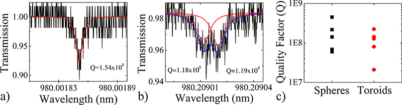
Ayrıntılı bir yaklaşım ultra-yüksek-Q cihazlar oluşturur doğrulamak için, biz de bir çizgi kalınlığı (Δλ) ölçümü yapan ve yüklü hesaplayarak çeşitli aygıtları Q faktörü karakterizeSoru basit bir ifade ile: Q = λ / Δλ = ωτ, burada λ = rezonans dalga boyu, ω = frekans ve τ = foton ömrü. Daha önce ayrıntılı prosedürler 1,9 ve çeşitli cihazların bir karşılaştırma grafiği kullanılarak üretilen her aygıt için temsili spektrumları Şekil 3 'de gösterilmiştir. Tüm cihazların kalite faktörleri çoğunluğu 100 milyon üzerinde olması ile, yukarıda 10 milyon vardır.
Mikroküre spektrumu hafif saat yönünde veya saat yönünün tersine yayılan optik modu birine birleştiğinde belirten tek bir rezonans oldu. Ancak, toroid spektrumu aynı anda saat yönünde ve saat yönünün tersine modları içine birleştiğinde o ışık gösteren, bölünmüş bir rezonans sergiledi. Kaplin yerinde hafif bir kusur olduğunda bu olay meydana gelir. Bir çift-Lorentz için tayfı takılması ile, iki moddan Q faktörü tespit edilebilir. Bölünmüş rezonans fenomenna küre ve toroid rezonatörler hem de oluşabilir, ancak kusurları daha duyarlıdırlar ve küre göre daha az optik modlar olduğu gibi daha sık toroidler görülmektedir.

Mikroküre boşluğu üretim süreci Şekil 1. Akış çizelgesi. a) Rendering ve bir temizlenmeli ve parçalanabilen fiber optik b) optik mikrografı. c) Rendering, d) optik mikroskop ve e) rezonatör bir microspere elektron mikroskobu tarama.

Microtoroid boşluğu üretim süreci Şekil 2. Akış çizelgesi. a) Rendering, b) üst görünüm optik mikrograf ve c) fotolitografi ve BOE gravür tarafından tanımlanan dairesel oksit yüzeyi, elektron mikroskobu tarama yan görünümü. BOE oluşturduğu oksit hafif bir kama şeklinde not edin. d) Rendering, e) üst görünümoptik mikrograf ve f) XeF 2 aşındırma aşamasından sonra oksit pad elektron mikroskobu tarama yan görünümü. Oksit diski kama şekilli periferi muhafaza dikkat ediniz. microtoroid boşluğuna elektron mikroskobu tarama g) Rendering, h) üst görünüm optik mikrograf ve i) yan görünümü.

Şekil 3. A) mikroküre ve çizgi kalınlığı ölçüm yöntemi kullanılarak belirlenen b) microtoroid rezonans kaviteler Temsilcisi kalite faktörü spektrumları. Çok yüksek Q cihazlar, bir ışık, küçük bir defekt yansıyan ve saat yönünde ve saat yönünün tersine her iki yönde dolaşır olduğu, mod-bölme veya bir çift tepe gözlemleyebiliriz. c) Birkaç mikroküre ve microtoroid rezonans boşluklarının Q faktörleri gösteren Karşılaştırma grafiği. büyük rakam için buraya tıklayın .

Şekil 4. CO2 lazer reflow şematik set-up. CO 2 lazer ışını (katı mavi çizgi) yansır ve örnek odaklanmıştır. Bu 10.6 mikron / 10.6 mikron iletir ve 633 nm yansıtan 633 nm ışın birleştirici, geçer. Kiriş birleştiricinin off örnek optik sütun görüntüleri yansıması, bu nedenle görüntü biraz kırmızı. Bu kurulum için gerekli olan parçaların bir listesi Tablo 4'te yer almaktadır.

Şekil 5. Yanlış a) mikroküre ve b) microtoroid rezonans kaviteler reflowed. Demeti içinde yanlış yerleşimi nedeniyle, cihaz mal-oluşmuştur. c) bir düşük photomask ya da zayıf litografya bir sonucu olarak, toroid ay şekilli olup.
Tartışmalar
Herhangi bir optik yapısı olduğu gibi, üretim sürecinin her aşamasında temiz tutmak önem taşımaktadır. Litografi ve uydurmalarla konuda yazılmış çok sayıda kitap var gibi, aşağıdaki önerileri kapsamlı olmalı, ancak araştırmacılar karşılaştıkları daha yaygın sorunları birkaç vurgulamak için değildir. 19-20
Microtoroid çevresindeki bir homojenlik başlangıç diskin yeknesaklık göre belirlenmesinden dolayı, bu kalıp çok dairesel disk i?...
Açıklamalar
Çıkar çatışması ilan etti.
Teşekkürler
A. Maker Annenberg Vakfı Doktora Araştırma Bursu tarafından desteklenen ve bu çalışma, Ulusal Bilim Vakfı [085.281 ve 1.028.440] tarafından desteklenmiştir.
Malzemeler
| Name | Company | Catalog Number | Comments |
| Bölümünün adı | Şirket | Katalog numarası | Yorumlar |
| Fiber scribe | Newport | F-RFS | Isteğe bağlı |
| Fiber optik | Newport | F-SMF-28 | Optik lif herhangi bir tür kullanılabilir. |
| Fiber kaplama striptizci | Newport | F-STR-175 | Tel soyucu de kullanılabilir |
| Etanol | Herhangi bir satıcı | Solvent seviyesi saflık | Metanol veya izopropanol ikamelerdir |
Tablo 1. Microsphere Fabrikasyon Malzeme.
| Reaktif Adı | Şirket | Katalog numarası | Yorumlar |
| 2μm termal yetiştirilen silika ile Silikon gofret | WRS Malzemeleri | n / a | Biz içsel 8, <100>, 4 "çap kullanılabilir |
| HMDS (heksametildisilazan) | Aldrich | 440191 | |
| Rezist | Shipley | S1813 | |
| Geliştirici | Shipley | MF-321 | |
| Geliştirilmiş - HF Tamponlu | Transene | n / a | Geliştirilmiş tamponlanmış HF düz BOE veya HF daha etch daha pürüzsüz, daha iyi kalite verir |
| Aseton, metanol, izopropanol | Herhangi bir satıcı | % 99.8 saflıkta |
Tablo 2. MICRotoroid Fabrikasyon Malzeme.
| Ekipman Adı | Üretici | Katalog numarası | Yorumlar |
| Spinner | Solitec | 5110-ND | Herhangi bir spinner kullanılabilir. |
| Aligner | Süß Microtec | MJB 3 | Herhangi bir hizalama kullanılabilir. |
| XeF 2 yakıcısı | Gelişmiş Haberleşme Devices, Inc | # ADCETCH2007 |
Tablo 3. Microtoroid İmalat Ekipmanları.
| Bölümünün adı | Şirket | Katalog numarası | Yorumlar |
| CO 2 Lazer | Synrad | Series 48 | |
| 3-Eksen aşamasında | OptoSigma | 120-0770 | Hem de diğer üreticilerin mevcuttur. |
| Si Reflektör 1 "çap) | II-VI | 308325 | Hem de diğer üreticilerin mevcuttur. |
| Kinematik gimbal montaj (Si reflektör için) | Thor Labs | KX1G | Hem de diğer üreticilerin mevcuttur. |
| Işın birleştirici (1 "çap) | Meller Optik | L19100008-B0 | Hem de diğer üreticilerin mevcuttur. |
| 4 "Odak uzunluğu Lens (1" çap) | Meller Optik veya II-VI | Gibi başka satıcılardan alınabilen yanı | |
| Çeşitli mesaj, objektif bağlar | Thor Labs, Newport, Edmund Optik veya Optosigma | ||
| Yakınlaştırma 6000 makine görme sistemi | Navitar | n / a | Gerçek zamanlı görüntüleme için jenerik USB kamera ve bilgisayar gerektirir. Bu bir kit olarak satın alınmaktadır. |
| Yakınlaştırma 6000 sistemi için Focuser | Edmund Optik | 54-792 | Hem de diğer üreticilerin mevcuttur. |
| Yakınlaştırma 6000 XZ Eksen Pozisyonerler | Parker Daedal | CR4457, CR4452, 4499 | CR4457 X-ekseni ise, CR4452 Z ekseni ise, 4499 dirseği monte edilir. |
Tablo 4. CO 2 Lazer Reflow Set-up.
Referanslar
- Armani, D. K., Kippenberg, T. J., Spillane, S. M., Vahala, K. J. Ultra-high-Q toroid microcavity on a chip. Nature. 421, 925-928 (2003).
- Gorodetsky, M. L., Savchenkov, A. A., Ilchenko, V. S. Ultimate Q of optical microsphere resonators. Optics Letters. 21, 453-455 (1996).
- Armani, A. M., Kulkarni, R. P., Fraser, S. E., Flagan, R. C., Vahala, K. J. Label-Free, Single-Molecule Detection with Optical Microcavities. Science. 317, 783 (2007).
- Choi, H. S., Ismail, S., Armani, A. M. Studying polymer thin films with hybrid optical microcavities. Optics Letters. 36, 2152-2154 (2011).
- Aoki, T. Observation of strong coupling between one atom and a monolithic microresonator. Nature. 443, 671-674 (2006).
- Hsu, H. -. S., Cai, C., Armani, A. M. Ultra-low threshold Er:Yb sol-gel microlaser on silicon. Optics Express. 17, 23265 (2009).
- Zhu, J. On-chip single nanoparticle detection and sizing by mode splitting in an ultrahigh-Q microresonator. Nature Photonics. 4, 46-49 (2009).
- Zhang, X., Choi, H. -. S., Armani, A. M. Ultimate quality factor of silica microtoroid resonant cavities. Applied Physics Letters. 96, 153304 (2010).
- Vernooy, D. W., Ilchenko, V. S., Mabuchi, H., Streed, E. W., Kimble, H. J. High-Q measurements of fused-silica microspheres in the near infrared. Optics Letters. 23, 247-249 (1998).
- Saleh, B. E. A., Teich, M. C. . Fundamentals of Photonics. , (2007).
- Ilchenko, V. S. Crystal quartz optical whispering-gallery resonators. Optics Letters. 33, 1569-1571 (2008).
- Soteropulos, C., Hunt, H., Armani, A. M. Determination of binding kinetics using whispering gallery mode microcavities. Applied Physics Letters. 99, 103703 (2011).
- Barclay, P. E., Srinivasan, K., Painter, O., Lev, B., Mabuchi, H. Integration of fiber-coupled high-Q SiNx microdisks with atom chips. Applied Physics Letters. 89, (2006).
- Srinivasan, K., Painter, O. Mode coupling and cavity-quantum-dot interactions in a fiber-coupled microdisk cavity. Physical Review. A. 75, (2007).
- Xu, Q. F., Lipson, M. All-optical logic based on silicon micro-ring resonators. Optics Express. 15, 924-929 (2007).
- Martin, A. L., Armani, D. K., Yang, L., Vahala, K. J. Replica-molded high-Q polymer microresonators. Optics Letters. 29, 533-535 (2004).
- Chao, C. Y., Guo, L. J. Polymer microring resonators fabricated by nanoimprint technique. Journal of Vacuum Science Technology B. 20, 2862-2866 (2002).
- Armani, A. M., Armani, D. K., Min, B., Vahala, K. J., Spillane, S. M. Ultra-high-Q microcavity operation in H2O and D2O. Applied Physics Letters. 87, 151118 (2005).
- Kovacs, G. T. A. . Micromachined Transducers Sourcebook. , (1998).
- Kovacs, G. T. A., Maluf, N. I., Petersen, K. E. Bulk Micromaching of Silicon. Proceedings of the IEEE. 86, 1536-1551 (1998).
Yeniden Basımlar ve İzinler
Bu JoVE makalesinin metnini veya resimlerini yeniden kullanma izni talebi
Izin talebiThis article has been published
Video Coming Soon
JoVE Hakkında
Telif Hakkı © 2020 MyJove Corporation. Tüm hakları saklıdır