
Series and Parallel Resistors
Genel Bakış
Source: Yong P. Chen, PhD, Department of Physics & Astronomy, College of Science, Purdue University, West Lafayette, IN
This experiment demonstrates how current is distributed in resistors connected in series or parallel, and thus describes how to calculate the total "effective" resistance. Using Ohm's law, it possible to convert between the voltage and current through a resistance, if the resistance is known.
For two resistors connected in series, (meaning that they are wired one after the other), the same current will flow through them. The voltages will add up to a "total voltage", and thus, the total "effective resistance" is the sum of the two resistances. This is sometimes called a "voltage divider" because the total voltage is divided between the two resistors in proportion to their individual resistances.
For two resistors connected in parallel, (meaning that they are both wired between two shared terminals), the current is split between the two while they share the same voltage. In this case, the reciprocal of the total effective resistance will equal the sum of the reciprocals of the two resistances.
Series and parallel resistors are a key component to most circuits and influence how electricity is used in most applications.
İlkeler
The electrical current I flowing through a "device" (such as a resistor with resistance R) is defined as the amount of charge Q flowing through the device per unit time:
 (Equation 1)
The current through a resistor (with resistance R) is related to the voltage drop V across the resistor by Ohm's law:
 (Equation 2)
Resistors in Series:
For two resistors (R1 and R2) connected in series (Figure 1), a current continuity means that the current through R1 equals the current through R2, which equals the current through both resistors. This gives:
 (Equation 3)
Because the voltage drop across a device represents the potential difference between the two "terminals", the total voltage drop V across both resistors is the sum of the individual voltage drops across each resistor:
 (Equation 4)
Thus, with Ohm's law, the total voltage drop is equal to the effective resistance, or sum of R1 and R2, times the current:
 (Equation 5)
Therefore, the total or "effective" resistance R of the whole series combination equals V/I. Thus, the effective resistance of resistors in series equals the sum of the individual resistances. That is,
 (Equation 6)
This can be also generalized to a series combination of multiple resistors. For example, if a large resistance is connected in series with a very small resistance, the total resistance will be mainly determined by the large resistor.
Further, the total current I is equal to the total voltage drop V divided by the effective resistance, or the sum of the two resistances:
 (Equation 7)
Thus, the individual voltage drops (V1 and V2) can be related to the total voltage drop V as:
 (Equation 8)
and,
 (Equation 9)
This relationship describes the "voltage division," or how the voltage is divided among two series resistors proportional to the resistance.
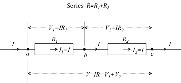
Figure 1: Diagram showing two resistors connected in series.
Resistors in Parallel:
If the two resistors are instead connected in parallel, as shown in Figure 2, they share the same voltage drop V, but the total current I is split between them:
 (Equation 10)
and,
 (Equation 11)
Therefore:
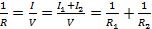 (Equation 12)
which also means that the effective resistance, R, is equal to the "product-sum" of the two parallel resistances, or:
 (Equation 13)
Any resistor is also a conductor, and the conductance G of a resistance R is defined as the inverse of the resistance:
 (Equation 14)
where the second equality is due to Ohm's law (Equation 2).
Then for parallel resistors:
 (Equation 15)
that is, "parallel conductances add".
If a large resistance is connected in parallel with a very small resistance, the total resistance is mainly determined by the small resistance, which has the large conductance.
For a parallel connection, the current will be divided in proportion to the conductance
 , and
, and  (Equation 16)
which also means,
 , and
, and  (Equation 17)
(note however, the numerator is the other resistance).
For all of these examples, it is important to note that it is assumed that the wires connecting the resistors have negligibly small resistances as compared to R1 and R2. If not, the wires themselves should be modeled as resistors connected in series to R1 and R2, and add their resistances to become part of R1 and R2.

Figure 2: Diagram showing two resistors connected in parallel.
Prosedür
1. Practice on Generating and Measuring Current, Voltage, and Resistance
- Obtain a current source, a voltage source, and two multimeters that can measure voltage, current, and resistance.
- Obtain two 100-Ω resistors and two 10-Ω resistors.
- Obtain a breadboard, which is a convenient platform to connect and organize different circuit elements. The breadboard has many groups of pins. The pins of each group are connected together at the back of the board, and wires plugged into the same group are shorted together. A wire plugged into the same group of pins as a terminal of a circuit element is connected to that terminal. Different terminals of a circuit element not meant to be shorted should be plugged into different pin groups. In the following, the action of connecting two terminals means plugging them into the same pin group (in the figures, distinctive nodes labelled "a", "b", and "c" represent distinctive pin groups on the breadboard). This is done provided that such terminals are made of wires that can be conveniently inserted into a pin hole. Otherwise, it is possible to use cables, banana plugs, and clamps to make electrical connections (for example, from a terminal on the instrument to an exposed pin leg on the breadboard).
- Connect the output terminal of the current source to one terminal of the 100-Ω resistor, and then connect the other terminal of the resistor back to the other terminal of the current source.
- Generate 1 mA current through the resistor.
- Select the voltage measurement or voltmeter mode of the multimeter, and connect the two terminals of the multimeter to the two terminals of the resistor. Measure the voltage drop cross the resistor.
- A positive reading means that the potential at the positive terminal of the multimeter is higher than that at the negative terminal. Use the voltage reading to verify the Ohm's law relationship (Figure 3).
- Next, connect one terminal of a voltage source to one terminal of the resistor, and connect the other terminal of the resistor back to the other terminal of the voltage source. Produce a 10 V voltage across the 100-Ω resistor.
- Use the multimeter in the current measurement or ammeter mode, and connect the probes in series with the resistor. Measure the current through the resistor.
- A positive reading means that the electrical current is flowing from the positive terminal of the multimeter to the negative terminal. Then, verify Ohm's law (Figure 4).
- Note that the multimeter needs to be in series with a resistor to measure its current (ammeter), but needs to be in parallel with a resistor to measure its voltage drop (voltmeter). In these measurements, assume that the "internal" resistance of the ammeter is very small but that of the voltmeter is very large. If this is not rigorously true then the current or voltage measured by the meter would be different from the value before the connection of the meter.
- Finally, directly measure the resistance using the multimeter (Figure 5) by selecting the resistance measurement mode. Connect the two terminals of the meter with the two terminals of the resistor and read the resistance. Confirm that the resistance makes sense based on the previous current and voltage measurements.
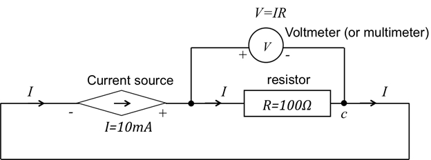
Figure 3: Circuit diagram of sourcing a current through resistor R and measuring voltage.
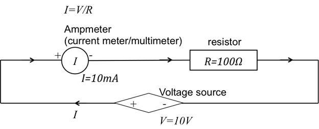
Figure 4: Circuit diagram of sourcing a voltage across resistor R and measuring current.
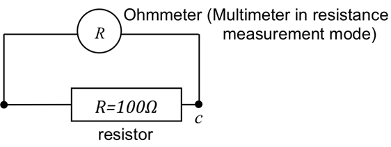
Figure 5: Connection of a multimeter to measure resistance of a resistor.
2. Resistors in Series
- Connect two 100-Ω resistors in series (refer to Figure 1). On the breadboard, this means plugging the two ends of the first resistor into two different pin groups (not shorted), say group a and b, and plugging the two ends of the second resistor into pin groups b and c (c is yet another pin group not shorted to a and b).
- Connect a common current of 10 mA through both resistors using a current source as described in step 1.4.
- Using a multimeter in voltmeter mode, measure the voltage drop across each resistor. Then confirm the resistance values of R1 and R2 using Ohm's law.
- Now use the voltmeter to measure the voltage V across the entire series combination (between points a and c in Figure 1), and obtain the total series resistance.
- Enter the measured resistance values, as shown in Table 1.
- Disconnect the power sources and meters, then use a voltage source to provide a total of 10 V across both resistors (between points a and c).
- Use a multimeter in ammeter mode to measure the current (I1) entering R1, and the current (I2) entering R2.
- Verify that I1 is equal to I2 (or approximately equal; any small difference might be due to slightly different configurations, including wire resistances that changed slightly).
- Repeat the procedure in step 2.1 for two 10-Ω resistors in series, and measure the wire resistance using the multimeter.
- Repeat the procedure in step 2.1 for one 100-Ω resistor in series with one 10-Ω resistor, and repeat the resistance measurements.
3. Resistors in Parallel
- Connect two 100-Ω resistors in parallel (refer to Figure 2). On the breadboard, plug the two ends of each resistor into two pin groups, say a and b.
- Source a common voltage drop of V = 10 V using a voltage source.
- Use a multimeter to measure the current I1 entering R1, thus confirming that R1 = V/I1. Then, measure I2 entering R2, thus confirming that R2 = V/I2.
- Now put the amp meter in front of the parallel combination (before point a in Figure 2), and obtain the total series resistance R = V/I.
- Repeat the above in step 3.1 for two 10-Ω resistors in parallel, and again for one 100-Ω resistor in parallel with one 10-Ω resistor.
4. LEDs in Series and Parallel Connection
- Obtain two small LED light sources, which can be treated as two resistors.
- Connect 1 V source to power 1 LED (similar connection as step 1.5), and observe its brightness.
- Now connect the two LEDs in parallel between the 1 V source (similar connection as in step 3.1), and observe their brightness.
- Now connect the two LEDs in series and between the 1 V source (similar connection as step 2.1.5), and observe their brightness again.
Sonuçlar
Representative results anticipated from the above procedure are listed below in Table 1 for resistors in series, and in Table 2 for resistors in parallel.
According to the results in Table 1, the total resistance R measured obeys Equation 6, where the resistances for components in series add to give the total resistance. The results in Table 2 show that the total resistance for resistors in parallel follows Equation 12 (or Equation 13), where the reciprocals (i.e., conductances) of the resistances in parallel add to give the total effective resistance.
When using LEDs in place of resistors, it is clear that the LEDs connected in parallel both have similar brightness to the single LED connected to the same voltage source. This is because the LEDs are powered by voltage, and the ones connected in parallel share the same voltage source (1 V in this case). Therefore, the configuration does not affect the operation of the each LED. In contrast, the two LEDs connected in series are dimmer than the single LED. This is because the two LEDs in series each receive only 0.5 V, as the voltage is split between them.
| R1 | R2 | Rseries |
| 100 Ω | 100 Ω | 200 Ω |
| 10 Ω | 10 Ω | 20 Ω |
| 100 Ω | 10 Ω | 110 Ω |
Table 1: Data collected for two series resistances R1 and R2 and the total effective resistance R = Rseries.
| R1 | R2 | Rparallel |
| 100 Ω | 100 Ω | 50 Ω |
| 10 Ω | 10 Ω | 5 Ω |
| 100 Ω | 10 Ω | 9.1 Ω |
Table 2. Data collected for two parallel resistances R1 and R2 and the total effective resistance R = Rparallel.
Başvuru ve Özet
In this experiment, we have reviewed how to use voltage and current sources, and multimeters (voltmeter, current/amp meter, ohmmeter) to verify the current continuity law and Ohm's law. We also demonstrated how resistance adds in series connection, and how conductance adds in parallel connection.
Series and parallel connections are common in many circuit applications. For example, to use a voltage source V as a current source for some device with resistance R1, connect a much larger fixed resistance R2 with the voltage source and the device R1. Then, the current through R1 is approximately V/R2.
When any electrical appliance or equipment is plugged into a 110-V outlet on the wall, the connection is made in parallel with other instruments that may have already been plugged in. They all share the 110-V common voltage and each should operate without affecting others-within a certain range of operation conditions.
The author of the experiment acknowledges the assistance of Gary Hudson for material preparation and Chuanhsun Li for demonstrating the steps in the video.
Atla...
Bu koleksiyondaki videolar:

Now Playing
Series and Parallel Resistors
Physics II
33.2K Görüntüleme Sayısı

Electric Fields
Physics II
77.6K Görüntüleme Sayısı

Electric Potential
Physics II
105.1K Görüntüleme Sayısı

Magnetic Fields
Physics II
33.6K Görüntüleme Sayısı

Electric Charge in a Magnetic Field
Physics II
33.7K Görüntüleme Sayısı

Investigation Ohm's Law for Ohmic and Nonohmic Conductors
Physics II
26.3K Görüntüleme Sayısı

Capacitance
Physics II
43.8K Görüntüleme Sayısı

Inductance
Physics II
21.6K Görüntüleme Sayısı

RC/RL/LC Circuits
Physics II
143.0K Görüntüleme Sayısı

Semiconductors
Physics II
29.9K Görüntüleme Sayısı

Photoelectric Effect
Physics II
32.7K Görüntüleme Sayısı

Reflection and Refraction
Physics II
36.2K Görüntüleme Sayısı

Interference and Diffraction
Physics II
91.3K Görüntüleme Sayısı

Standing Waves
Physics II
49.9K Görüntüleme Sayısı

Sound Waves and Doppler Shift
Physics II
23.5K Görüntüleme Sayısı
JoVE Hakkında
Telif Hakkı © 2020 MyJove Corporation. Tüm hakları saklıdır