AC Synchronous Machine Characterization
Source: Ali Bazzi, Department of Electrical Engineering, University of Connecticut, Storrs, CT.
Three-phase wound-rotor synchronous motors are less popular than permanent magnet rotor synchronous motors due to the brushes required for the rotor field. Synchronous generators are much more common and available in most existing power plants, as they have excellent frequency and voltage regulation. Synchronous motors have the advantage of almost 0% speed regulation due to the fact that the rotor speed is exactly the same as the stator's magnetic field speed, causing the rotor speed to be constant, irrespective of how much the motor's shaft is loaded. Thus, they are very suitable for fixed speed applications.
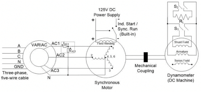
The objectives of this experiment are to understand the concepts of starting a three-phase synchronous motor, V-curves for various loads where the load affects the motor power factor, and the effect of loads on the angle between the terminal voltage and back e.m.f.
1. DC Test
- Turn on the low-power DC power supply with a short circuit across its terminals.
- Limit the current on the low-power DC power supply to 1.8 A.
- Turn off the supply and disconnect the short circuit.
- Connect the supply terminals across ports 1 and 4 of the synchronous motor.
- Turn on the supply and measure the DC voltage and current. Vary the voltage as needed to reach a current of 1.8 A.
- Turn off the supply, then repeat the previous
The DC phase resistance can be estimated from the DC test as the ratio of DC voltage to DC current when applied between a phase terminal and the neutral. The field resistance can be measured in a similar manner by applying DC voltage to the field winding and measuring the field current. The synchronous reactance (Xs), back e.m.f. of the machine (EA), and its related constant kφ can be found from the real power (P3
Synchronous machines are common in applications requiring constant speed on the motor's shaft with very tight speed regulations. Such applications include electrical clocks and hard disk drives, but extend to synchronous condensers, which are synchronous motors operating in the leading power factor region to provide reactive power to a load. Power factor correction is another term used with synchronous condenser applications. Note that the most common synchronous motors are permanent magnet motors, while the most common
Skip to...
Videos from this collection:

Now Playing
AC Synchronous Machine Characterization
Electrical Engineering
14.2K Views

Electrical Safety Precautions and Basic Equipment
Electrical Engineering
144.3K Views

Characterization of Magnetic Components
Electrical Engineering
14.9K Views

Introduction to the Power Pole Board
Electrical Engineering
12.4K Views

DC/DC Boost Converter
Electrical Engineering
56.4K Views

DC/DC Buck Converter
Electrical Engineering
21.0K Views

Flyback Converter
Electrical Engineering
13.2K Views

Single Phase Transformers
Electrical Engineering
20.1K Views

Single Phase Rectifiers
Electrical Engineering
23.3K Views

Thyristor Rectifier
Electrical Engineering
17.4K Views

Single Phase Inverter
Electrical Engineering
17.8K Views

DC Motors
Electrical Engineering
23.3K Views

AC Induction Motor Characterization
Electrical Engineering
11.6K Views

VFD-fed AC Induction Machine
Electrical Engineering
6.9K Views

AC Synchronous Machine Synchronization
Electrical Engineering
21.5K Views
Copyright © 2025 MyJoVE Corporation. All rights reserved


