Method Article
3Dプリント層における接合のリアルタイムイメージング
要約
非侵襲的でリアルタイムの技術により、ポリマーフィラメント内のナノスコピックポリマーの動きが3D印刷中に画像化されます。このモーションの微調整は、最適なパフォーマンスと外観を備えたコンストラクトを作成するために重要です。この方法は、プラスチック層融合の中核に到達し、最適な印刷条件と材料設計基準に関する洞察を提供します。
要約
最近では、3D印刷技術が製品の設計と製造の能力に革命をもたらしましたが、印刷品質の最適化は困難な場合があります。押出3D印刷のプロセスでは、薄いノズルを介して溶融材料を加圧し、以前に押し出された材料に堆積させます。この方法は、連続する層間の結合に依存して、強力で視覚的に魅力的な最終製品を作成します。最適な結果を得るには、ノズル温度、層の厚さ、印刷速度などの多くのパラメーターを微調整する必要があるため、これは簡単な作業ではありません。本研究では、押出成形時のポリマーダイナミクスを可視化する方法を提示し、層接合プロセスへの洞察を提供します。レーザースペックルイメージングを使用すると、塑性流動と融合を非侵襲的、内部的、および高い時空間分解能で分解できます。この測定は簡単に実行でき、最終的な印刷品質に影響を与える基本的なメカニズムを深く理解できます。この方法論は、さまざまな冷却ファン速度でテストされ、結果は、ファン速度が低いほどポリマーの動きが増加し、冷却ファンをオフにしたときの印刷品質の低下を説明しました。これらの知見は、この方法論が印刷設定を最適化し、材料の挙動を理解することを可能にすることを示している。この情報は、新しい印刷材料の開発とテスト、または高度なスライス手順に使用できます。このアプローチにより、押し出しのより深い理解を構築し、3D印刷を次のレベルに引き上げることができます。
概要
3D印刷の方法は、オブジェクトを層ごとに製造して目的の形状を形成する積層造形技術です。この方法は、その汎用性、手頃な価格、および使いやすさのおかげで、大規模で多様なユーザーベースを持っています。溶融堆積モデリングは、溶融プラスチックを所望の形状に堆積させるための移動押出機(直径数百ミクロンから数ミリメートル)を特徴とする1。押し出されたプラスチックは、以前に印刷されたプラスチックとの良好な融着を達成し、強く凝集性の材料を形成するために、一定時間液体のように振る舞う必要があります。ただし、プラスチックが印刷場所から流れて印刷品質が低下するのを防ぐために、印刷後すぐにプラスチックが冷えて固まる必要があります。加熱と冷却の間のこの微妙な相互作用は、最終的な3Dプリントされたオブジェクト2の機械的強度と幾何学的精度のバランスを直接支えることが示されています。最適な加熱と冷却のバランスをとるために、プラスチックは溶融温度のすぐ上の温度で押し出され、プリンターに取り付けられたファンヘッドを使用してプラスチックをすばやく冷却します。印刷温度と冷却速度の影響を深く理解することで、最も重要な領域で機械的または幾何学的結果を最大化する高度なスライスおよび印刷プロトコルを開発するために必要な洞察を得ることができます。これらのプロセスについてより多くの洞察を得るための努力は、表面温度3,4,5のみを視覚化し、プラスチックの内部温度を示さない赤外線(IR)イメージングに依存することがよくあります。溶融転移を超えた局所加熱は、ポリマーの移動度を大幅に増加させ、したがって、古い材料と新しい材料の間のポリマーの絡み合いを可能にします。この時間的に強化されたポリマーの動きは、最終的な凝集材料6,7の形成の要件ですが、IRイメージングは、表面温度8,9を介して間接的にしかポリマーの動きを測定できません。したがって、表面温度を層結合に変換するには、コア表面温度勾配と、さまざまな時間と長さのスケールにわたる関連する複雑なポリマーダイナミクスに関する正確な知識が必要です。層結合(すなわち、ポリマーの絡み合いプロセス)の直接測定は、先験的な情報や仮定なしに、バルク材料の凝集力の根底にあるメカニズムの視覚化を可能にする。
層結合の空間的および時間的分布を理解するために、プラスチックフィラメントを構成するポリマーのダイナミクスを直接定量化するイメージング技術がこの研究で採用されています。この技術であるレーザースペックルイメージング(LSI)は、干渉光散乱に依存して、化学組成に関係なくナノスコピック運動を視覚化します。サンプルの光学特性に応じて、表面温度8,9のみを報告するIRイメージングとは異なり、不透明な材料10,11,12に数ミリメートルからセンチメートルを正確に測定できます。これらの属性により、スペックルベースの方法は、もともと医療用途向けに開発されたものの、最近、多数の材料の動的プロセスを理解する上で普及しています10,11,12。近年、LSIは、セルフクリーニング液晶ポリマーネットワーク13,14などの先端高分子材料の挙動の解明や、ゴムの破壊予測15、自己修復材料の研究16に利用されています。
LSIを3Dプリンティングに応用する可能性については、前回の記事17で紹介し、リアルタイム解析機能を備えたポータブルLSIセットアップを紹介し、溶融プラスチックの堆積により、現在の層より数層下のポリマー運動が増加することが示されました。ここで紹介する論文では、多層接合の程度に対する冷却ファン速度の影響について体系的な研究を行っています。ポータブル機器の改良されたプラグアンドプレイバージョンが使用されており、光学系やプログラミングの専門知識がなくてもユーザーが操作できます。スペックル画像は、スペックル強度変動の振幅を可視化するフーリエ変換17を用いてリアルタイムで解析される。この装置には、スペックルカメラと位置合わせされた追加の明視野カメラがあり、LSIモーションマップを明視野画像とオーバーレイして、明視野光がモーションマップに影響を与えることなく解釈を容易にすることができます。この記事で紹介する実験的アプローチは、困難な形状や材料の3D印刷中に押し出されたプラスチックの溶融、層結合、および凝固に関するより多くの洞察を得るために使用できます。
プロトコル
1. LSI機器と3Dプリンターのセットアップと位置合わせ
- 振動を最小限に抑えるために、3Dプリンターを安定した面に置きます。LSI機器を横に置いて、カメラが印刷領域をはっきりと見えるようにします。LSI機器を3Dプリンターのビルドプレートより少し高く置き、視界が遮られないように少し下に傾けてください。
- レーザー照明と明視野照明をオンにして、それらがイメージング領域と位置合わせされていることを確認します。レーザー出力を20 mWに設定し、レーザーが広い領域(数平方センチメートル)に拡大されたセットアップボックスから出ることを確認し、出力密度が十分に低いことを確認します(レーザーポインターの数倍)レーザーゴーグルや黒いエンクロージャーなどの追加の安全対策なしで その場 で使用できます。
注意: レーザーを直接見ないでください。 - テストプリント(補足コーディングファイル1や補足コーディングファイル2など)から始めて、アライメントと実験のセットアップをより便利にします(手順1.3-1.6)。 LSIカメラが印刷領域に焦点を合わせていることを確認してください。
- この最初のテスト印刷中に、照明とデジタルカメラを最適に位置合わせします。撮像領域全体が均一に照らされるようにレーザーの方向を調整し、スペックルサイズがピクセルサイズよりわずかに大きくなるように絞りを調整します。
- フレームレートと露出時間を最適化して、露出不足と露出オーバーのピクセルの数を最小限に抑え、最大のダイナミックレンジを実現します。
- ライブLSIデータ解析に適したパラメータを選択します。最も重要なことは、溶融プラスチックと固化プラスチックの間で最良のイメージングコントラストを生成する周波数を選択することです。関心領域 (ROI) とカラーマップのスケーリングを調整します。この場合、フーリエ級数の長さ16を選択し、2番目の周波数の振幅を視覚化しました。スペックル画像収集レートは毎秒50フレームであるため、視覚化される周波数は6.25Hzです。
- 1回の3Dプリント実験用の画像をキャプチャするためのLSI機器を準備します。画像を保存する頻度と期間を選択します。この場合、画像は0.25秒ごとに保存され、プリンタヘッドのパスごとに複数の画像が保存されました。各実験では、各印刷ジョブに最大12分かかったため、画像は15分間保存されました。
2. 3DプリントデザインとGコードの準備
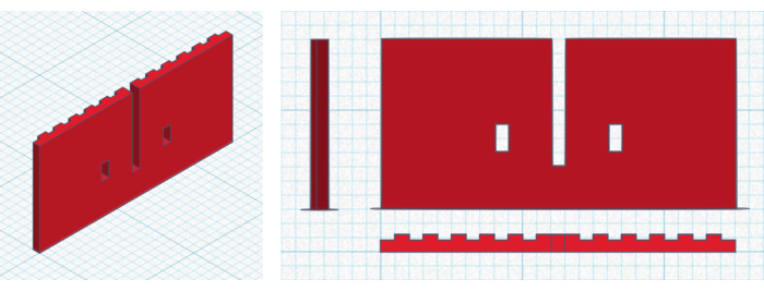
- 選択した3D描画ソフトウェアを使用してオブジェクトを描画し、オブジェクトを.stlファイルとしてエクスポートします。この場合、 図 1 に示されている隆起と穴のある壁が使用され、 補足コーディング ファイル 1 からダウンロードできます。
- .stl ファイルをスライス ソフトウェアにインポートし、印刷設定を選択します。これらの設定は、材料の選択と3Dプリンターモデルによって異なります。この調査で使用するケースでは、 表 1 に示す設定を使用します。できれば白またはレーザー光を大きな吸収なしに散乱させる任意の色のフィラメントを使用してください。
- スライスソフトウェアの スライス ボタンを押して、プリントヘッドのレイヤーと移動経路を取得します。スライス ソフトウェア構成ファイルは、 補足コーディング ファイル 3 にあります。
- 生成されたGコード(補足コーディングファイル2)を保存し、3Dプリンターに送信します。

図1:オブジェクト設計。 オブジェクト デザインの側面、正面、上面からの 3D ビュー(左)と 2D ビュー(右)。グリッドは 1.0 mm x 1.0 mm を表し、1.0 cm x 1.0 cm は太字で示しています。壁は25mm×12mm×1.2mm(幅×高さ×奥行き)で、尾根の幅は1.0mm、奥行きは0.4mm、隔ては1.0mmである。窓の幅は1.0 mm、高さは2.0 mmです。3Dデザインは、 補足コーディングファイル1にあります。 この図の拡大版を表示するには、ここをクリックしてください。
| プロパティ/設定 | 価値 |
| フィラメント | ポリ乳酸(PLA)、ホワイト |
| ノズル径 | 0.4 ミリ |
| 層の厚さ | 0.2ミリメートル |
| ノズル温度 | 210 °C |
| 冷却ファンの速度 | 100% |
| 印刷速度 | 10 ミリメートル/秒 |
| 走行速度 | 10 ミリメートル/秒 |
| ベッド温度 | 60 °C |
表1:3Dプリント設定。 オブジェクトデザインのスライスに使用される設定とプリンターのプロパティ。2番目の実験では、ファン速度を手動で0%に変更しました。
3. 実験の実施
- 3Dプリンターを起動し、ウォームアップ期間が終了するのを待ちます。
- LSI測定はいつでも開始できますが、不要なデータ保存を防ぐため、プラスチックが押し出され始めたらLSI測定を開始してください。
- 3Dプリンターが終了するのを待ってから、LSI測定を停止します。
- 得られたデータを画像表示ソフトウェアにロードし、印刷物を目視検査します。印刷中に測定されたプラスチックポリマーの動きを、最終的な構造的完全性および表面品質と比較します。
結果
実験のターゲットとして、背面に隆起のある壁、2つの窓、大きな穴という単純な物体が描かれました(図1)。オブジェクトは、 表 1 にリストされているプリンター設定とプロパティでスライスされました。
LSI機器を3Dプリンターに合わせて実験を行いました。ユーザーフレンドリーなセットアップは、アライメント中に役立ち、プラスチック押出成形と測定されたポリマーの動きを簡単に比較できる追加の明視野カメラを備えています。スペックルカメラと明視野カメラの両方に、他のチャネルからの干渉を防ぐ光学フィルターが装備されています。セットアップに関する技術的な詳細については補足 ファイル1に、分析ルーチンの説明は 補足ファイル2に示されています。この実験の結果のハイライトを 図2に示し、完全なムービーは 補足ムービー1にあります。前に示したように、実験は、自作の機器17でも同様に行うことができる。

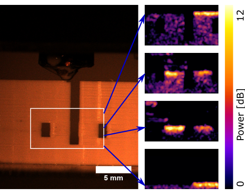
図2:冷却ファン速度100%での印刷のタイムラプス。 左:プリンタがほぼ完成したときのオブジェクトの明視野、正面図。印刷の品質は検査時に良好に見えます。サーフェスにはレイヤーラインが表示されますが、全体的に設計されたジオメトリが作成されています。右:印刷プロセス中の白い描写された領域からの4つのLSIスナップショット。青い矢印は、LSI画像が明視野画像と時間的に一致しないため、スナップショット時の印字ヘッド位置を示しています。各スナップショットの明るい色は、最近印刷されたレイヤーで観察されるポリマーの動きの増加を示します。運動が強化された領域(溶接ゾーン)は、複数の層の厚さであることに注意してください。実験の詳細動画は 補足動画1でご覧いただけます。 この図の拡大版を表示するには、ここをクリックしてください。
これらの結果を補完するために、印刷物を目視検査した。これらの一般的に使用されるポリマーフィラメントと印刷設定で予想されるように、品質は良好でした。設計されたジオメトリは確かに再現され、表面は均一で、各レイヤーに小さな線が見えました。LSIデータにより、印刷プロセスに関する深い洞察を得ることができました。押し出されたばかりのプラスチックは移動性が高いように見え、冷却するにつれて移動性は徐々に低下しました。移動性の高い領域(すなわち、溶接ゾーン)の高さは、印刷手順全体で4〜5層の厚さであり、明確に定義された層融合期間を示しています。
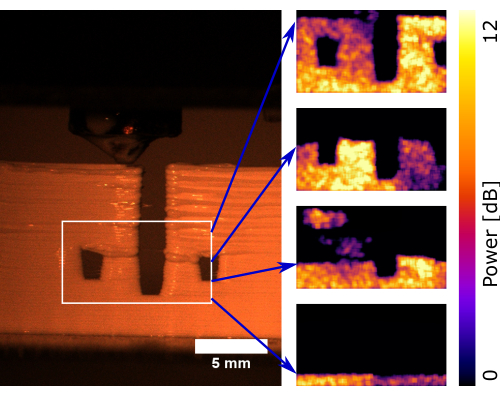
冷却ファンの速度を手動で0%に調整して実験を繰り返した。この設定では、プラスチックが十分に速く冷却されず、印刷品質に影響を与えました。結果のハイライトを 図3に示し、詳細な動画は 補足動画2をご覧ください。

図3:冷却ファン速度0%での印刷のタイムラプス。 左:プリンタがほぼ完成したときのオブジェクトの明視野、正面図。印刷の視覚的品質が悪いように見えます。表面には不規則な層線と大きな塊が見られます。さらに、全体的に設計されたジオメトリは不完全に再現されています。特に、窓や穴が変形しています。右:印刷プロセス中の白い描写された領域からの4つのLSIスナップショット。青い矢印は、LSI画像が明視野画像と時間的に一致しないため、スナップショット時の印字ヘッド位置を示しています。各スナップショットの明るい色は、オブジェクト全体で観察できるポリマーの動きの増加を示しています。実験の詳細動画は補足 動画2でご覧いただけます。 この図の拡大版を表示するには、ここをクリックしてください。
予想通り、3Dプリントされた構造の目視検査では、実際に印刷品質が悪いことが示されました。層は不均一に分布しており、設計された形状は変形して再現されました。図2と図3の明視野画像を比較すると、印刷結果の表面品質と形状に対する冷却ファンの主な影響がわかります。この効果の原因は、図2と図3のLSI結果を比較して決定しました。冷却ファンの速度を100%にすると、押し出されたプラスチックの数層下の領域でポリマーの動きが促進されました。そのため、各層を適度に数回液化して、塑性流動のない層接合を実現しました。冷却ファンの回転数を0%にすると、対象物全体を通してポリマーの動きが促進されました。したがって、各層は何度も液化され、新たに押し出されたプラスチックに非常に近くなり、塑性流動によって幾何学的精度が失われました。
より穏やかな状況での冷却ファン効果のより定量的なビューを得るために、冷却ファンの速度を体系的に変化させました。オブジェクトの設計は、穴や隆起のない25 mm x 12 mm x 0.8 mm(幅x高さx奥行き)の壁に簡略化されました。表1と同じ印刷設定を使用した。実験は12回行われ、冷却ファンの速度はそれぞれ0%、20%、40%、60%、80%、および100%でした。得られた動画は、補足動画3、補足動画4、補足動画5、補足動画6、補足動画7、補足動画8、ならびに補足符号化ファイル6、補足符号化ファイル7、補足符号化ファイル8、補足符号化ファイル9、補助符号化ファイル10、および補助符号化ファイル11に見出すことができる。
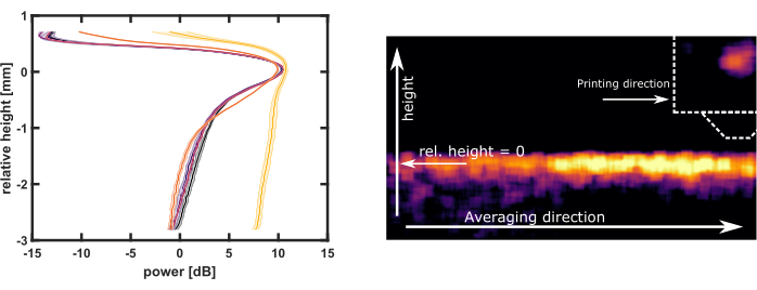
ファン速度の違いで溶接ゾーンを定量的に比較するために、LSIの結果に対して高度なデータ分析が行われました。このデータ分析の目的は、溶接ゾーン内のポリマーの動きの範囲の高さプロファイルを取得することでした。関連する完全にコメントされたMATLABスクリプトは、 補足コーディングファイル4 にあり、簡単に説明されています。動画内のすべてのLSI画像について、水平方向の平均を取ることによって高さプロファイルが計算されます。プリントヘッドがROIにある画像のプロファイルは、溶接ゾーンの周りに明確なピークを示しています。これらのプロファイルを排他的に選択するには、ピークが8 dBを超えるプロファイルのみが考慮されます。このピークがROIの端に近すぎるプロファイルも破棄されます。その後、すべてのプロファイルのピーク位置をアライメントして、ポリマーが最も可動性である高さに対する平均プロファイルを示します。6つの異なる冷却ファン速度の結果のプロファイルを 図4にプロットします。

図4:冷却ファン速度の体系的な変化の高さプロファイル。左:補足コーディングファイル4の高度なデータ分析スクリプトから取得した、冷却ファン速度100%(黒)、80%(青)、60%(紫)、40%(赤)、20%(オレンジ)、および0%(黄)の溶接ゾーンプロファイル。影付きの領域は、重複する実験間の標準偏差です。右の回路図は、標準的なLSIイメージのプロファイルを取得するための平均化手順を説明しています。得られたすべてのプロファイルのピークの最大値を揃えることによって、溶接ゾーンが得られます。溶接ゾーンの最大値(相対高さ= 0)は、ポリマーが最も可動性が高い高さです。各実験の詳細なLSIおよび明視野動画は、補足動画3、補足動画4、補足動画5、補足動画6、補足動画7、 補足動画8でご覧いただけます。 この図用に印刷されたオブジェクトは、補足コーディングファイル5にあり、対応するGコードファイルは補足コーディングファイル6にあります。この図の拡大版を表示するには、ここをクリックしてください。
40%〜100%冷却の溶接ゾーンプロファイルはほぼ同じでした。20%冷却のための溶接ゾーンには、いくつかのより深い層に達するショルダーがありました。0%冷却の溶接ゾーンは、測定領域全体に広がっています。ポリマーが最も可動性であった高さは、最後に印刷された層またはそのわずかに下にあった。この現象は、移動度ピークより上に印刷物が存在するため、正の相対高さにLSI信号が存在することを説明しています。すべての場合において、溶接ゾーンは0.2 mmの層の厚さよりはるかに深く達しました。
補足ファイル1:LSIのセットアップ.xls。 ここで使用するLSI機器のハードウェアパラメータ。 このファイルをダウンロードするには、ここをクリックしてください。
補足ファイル2:LSI解析.docx. 生スペックル画像のLSI画像への変換について解説します。 このファイルをダウンロードするには、ここをクリックしてください。
補足動画1: 図2に記載のLSI及び明視野実験の動画。 映画は12.5倍のリアルタイム速度で再生されます。上段がLSIの結果、下段がLSIのROIが示された同期明視野図です。 この動画をダウンロードするには、ここをクリックしてください。
補足動画2: 図3に記載の実験のLSI及び明視野動画。 映画は12.5倍のリアルタイム速度で再生されます。上段がLSIの結果、下段がLSIのROIが示された同期明視野図です。 この動画をダウンロードするには、ここをクリックしてください。
補足動画3: 図4で説明した100%冷却ファン速度実験。 映画は12.5倍のリアルタイム速度で再生されます。上段がLSIの結果、下段がLSIのROIが示された同期明視野図です。 この動画をダウンロードするには、ここをクリックしてください。
補足動画4: 図4で説明した80%の冷却ファン速度の実験。 映画は12.5倍のリアルタイム速度で再生されます。上段がLSIの結果、下段がLSIのROIが示された同期明視野図です。 この動画をダウンロードするには、ここをクリックしてください。
補足動画5: 図4で説明した60%の冷却ファン速度実験。 映画は12.5倍のリアルタイム速度で再生されます。上段がLSIの結果、下段がLSIのROIが示された同期明視野図です。 この動画をダウンロードするには、ここをクリックしてください。
補足動画6: 図4で説明した40%の冷却ファン速度実験。 映画は12.5倍のリアルタイム速度で再生されます。上段がLSIの結果、下段がLSIのROIが示された同期明視野図です。 この動画をダウンロードするには、ここをクリックしてください。
補足動画7: 図4で説明した20%の冷却ファン速度実験。 映画は12.5倍のリアルタイム速度で再生されます。上段がLSIの結果、下段がLSIのROIが示された同期明視野図です。 この動画をダウンロードするには、ここをクリックしてください。
補足動画8: 図4で説明した冷却ファン速度0%の実験。 映画は12.5倍のリアルタイム速度で再生されます。上段がLSIの結果、下段がLSIのROIが示された同期明視野図です。 この動画をダウンロードするには、ここをクリックしてください。
補足コーディングファイル1:wall_with_holes.stl。 図 1 で説明したオブジェクトの 3D 設計。このファイルをダウンロードするには、ここをクリックしてください。
補足コーディングファイル2:wall_with_holes.gcode。スライスされたオブジェクトは、表 1 の設定で wall_with_holes.stl になります。このファイルをダウンロードするには、ここをクリックしてください。
補足コーディングファイル3:config.ini。 スライス ソフトウェアの構成ファイル。 このファイルをダウンロードするには、ここをクリックしてください。
補足コーディングファイル4:AdvancedDataAnalysis_FanSpeed時 冷却ファンのスイープデータに対して高度なデータ分析を実行するスクリプトとプロット 図 4.スクリプトは完全にコメントされています。 このファイルをダウンロードするには、ここをクリックしてください。
補足コーディングファイル5:wall.stl。図 4 のデータの収集に使用したオブジェクトの 3D 設計。このファイルをダウンロードするには、ここをクリックしてください。
補足コーディング ファイル 6: wall_100%fan.gcode。 冷却ファン速度100%のスライスされたオブジェクト wall.stl 。 このファイルをダウンロードするには、ここをクリックしてください。
補足コーディング ファイル 7: wall_80%fan.gcode。 冷却ファン速度が80%のスライスされたオブジェクト wall.stl 。 このファイルをダウンロードするには、ここをクリックしてください。
補足コーディング ファイル 8: wall_60%fan.gcode. 冷却ファン速度が60%のスライスされたオブジェクト wall.stl 。 このファイルをダウンロードするには、ここをクリックしてください。
補足コーディング ファイル 9: wall_40%fan.gcode。 スライスされたオブジェクト wall.stl 冷却ファン速度 40%。 このファイルをダウンロードするには、ここをクリックしてください。
補足コーディング ファイル 10: wall_20%fan.gcode。 冷却ファンの速度が20%のスライスされたオブジェクト wall.stl 。 このファイルをダウンロードするには、ここをクリックしてください。
補足コーディング ファイル 11: wall_0%fan.gcode. 冷却ファンの速度が0%のスライスされたオブジェクト wall.stl 。 このファイルをダウンロードするには、ここをクリックしてください。
ディスカッション
本研究で説明した実験と結果は、LSIが積層造形における層接合のより深い理解を可能にする容易に適用できるツールであることを示しています。LSIはポリマーの動きを直接測定することを可能にしますが、ポリマー鎖の相互浸透とそれに続く絡み合いによってコヒーレントな材料を形成するために微調整する必要があります。その場で層結合を測定するための最も一般的な代替手段は、赤外線イメージング3,4,5です。この確立された方法は、材料内部のポリマーの動きの間接的な測定であるプラスチック8,9の局所的な表面温度を画像化します。プラスチックが高温になると、動きが速くなり、接着が強くなります。ただし、印刷温度は溶融温度とガラス転移温度6,7を横切るため、温度と運動の関係は線形ではありません。この自明ではない関係は、LSI画像で直接観察することができます。具体的には、液体のような上部領域と固体状の下部領域の間に急激な遷移があり、温度勾配ははるかに緩やかであると予想されます。IRイメージングのもう一つの欠点は、表面温度のみを測定するのに対し、LSIは通常、材料内の数ミリメートルの深さのポリマーの動きを測定することです。
IRイメージングと同様に、このLSIの実装は本質的にポイントアンドシュート方式です。カメラを関心領域に向けることができれば、その 場 で使用できます。汎用性の高い三脚と0.7mの長い作動距離により、利用可能な任意の3Dプリンターを自由に使用できます。重要なのは、LSIはナノスコピックな動きに敏感であるため、周囲からの振動や印刷プロセス自体を最小限に抑える必要があることです17。たとえば、同じテーブルで別のタスクを実行したり、ドアをバタンと閉めたりすると、干渉が発生します。したがって、セットアップを注意深く歩き回る必要があります。ただし、部屋の照明や空気の流れは、通常、プロセスを妨げません。
LSIは、層接合プロセスに関する詳細な洞察を提供し、IRイメージングと同じくらい簡単に適用できます。LSIは、高度な3D印刷方法の開発と理解を支援する上で大きな可能性を秘めていると考えています。冷却ファンの速度スイープは、LSIと3D印刷を組み合わせることで何ができるかを垣間見ることができます。冒頭で説明したように、最適な冷却速度は、プラスチックを溶融状態に保ち、層結合を改善することと、流れを防ぐのに十分な速さで冷却することのバランスです。40%〜100%の冷却ファン速度の結果は非常に似ていました。実際、これらのファン速度は流れを示さず、良好な表面品質を生み出しました。冷却ファンの回転数0%では、印刷箇所から材料が流れ出始めましたが、LSI測定では十分な層接合が見られました。私たちの結果に基づいて、20%の冷却ファン速度は、表面品質を損なうことなくわずかに改善された層接合を達成するために最適である可能性があります。ただし、実際に適用できる結論を導き出すには、0%から40%の間のより多くの冷却ファン速度を評価する必要があります。また、所望の特性に対するポリマー運動の影響を客観的かつ完全に把握するために、表面品質と材料強度の定量的測定値を確立することも望ましいです。この追加により、クリエイティブな3Dプリントの進歩を評価するためのアプローチをより強力にすることができます。
LSI解析用に選択された正確な設定は、液体のようなプラスチック相と固体のようなプラスチック相を明確に区別できる限り、重大なエラーが発生しにくいです。溶融温度とガラス転移温度を交差させるとポリマーの動きが大きく変化するため、幅広いLSI設定でコントラストをよく捉えることができます。これは、材料サプライヤーが推奨する3Dプリンター設定を使用した単純なオブジェクト(ストレートウォールなど)のテストプリントで簡単にテストできます。より高度なLSIユーザーにとっては、周波数範囲を深く掘り下げることで、さまざまな種類のポリマーの動きを定量的に区別できるため、追加情報を得ることができます。たとえば、高周波ポリマーの動きは、プリンタヘッドの近くにのみ存在する最高温度に関連しています。低周波ポリマーの動きは中程度の温度に関連しており、これはプリンタヘッドの周りのはるかに広い領域に存在し、またはるかに長い時間存在します17。累積的な低周波ポリマー運動の結合度が、短い高周波運動(動的機械解析など)の結合度と等しくなるかどうかを調べる必要があります。カラーマップのスケーリング、ROI、保存間隔、テストの長さなど、他のほとんどの設定は、視覚的に明確で魅力的な結果を得るためにのみ選択されています。3Dプリンティングの設定に関しては、LSIにより、ユーザーが任意の設定を変更した結果を客観的に評価できるため、自由度も高くなります。特に、印刷速度を大幅に変更すると、LSIデータの解釈が変わります。本研究では、プリンタヘッドを1回通過させる際に複数のLSI画像を撮影するために、10mm/sの低速印刷と移動速度を用いた。PLAの印刷速度を60mm/sとすると、LSI画像1枚につき約1層フル印刷となり、1層内で平均化が発生します。300 mm/s以上のハイエンド速度を試すと、複数のレイヤーで平均化が発生します。それにもかかわらず、これは正確な印刷形状とLSI設定に完全に依存しており、経験豊富なLSIユーザーは、高度な機械設計、視野のサイズの調整、またはより高速なカメラの使用によって簡単に軽減できます。どちらのアプローチでも、より強力なレーザーが必要であり、反射型プリンターヘッドと組み合わせて、追加のレーザー安全対策が必要です。比較的遅い印刷速度は、印刷速度が遅いとプラスチックへの熱伝達が増加することが以前に証明されているため、層結合にもプラスの影響を与えます5。
このアプローチの可能な新しい方向性の1つは、新しい材料のテストです。例えば、LSIは、関連する遷移を視覚化し、最上層の塗布時に5層の溶接ゾーンを与える推奨プリンタ設定を客観的に定量化するために使用できます。別のアプリケーションは、ブリッジ、オーバーハング、鋭いコーナーなど、印刷品質が確実に良くない特定の状況で溶接ゾーンを研究することです。困難な状況での溶接ゾーンをよりよく理解できれば、Gコードで補正できるはずです。ビルドプレート18への良好な接着性を達成するために、第1の層を他の層よりも熱くかつ遅く印刷することは既に一般的な慣行である。同様の動的Gコードスライスの使用を想定しており、たとえば、ファンの冷却を調整してコーナーやブリッジを生成できます。また、外壁素材をより滑らかな仕上がりで印刷し、残りの素材とインフィルをより粗く、しかしより強く充填して、材料の強度と外観の両方を最大化することもできます。
この記事では、プラスチック押出後の層接合プロセスを研究するためのLSIのアプリケーションについて説明しました。この手法は、3D印刷中にリアルタイムで先験的な仮定なしに下にあるポリマーの動きを視覚化できるため、このタスクに最適です。ただし、材料の凝集力に関する情報は提供されないため、追加のテストが必要になります。議論されている他の欠点は状況によるものです。毎秒4枚のLSI画像という限られたイメージング速度は、より大きなレーザーと追加のレーザー安全対策で増加させることができ、振動感度には予防措置または振動低減ハードウェアが必要です。LSIは、安価で小型のデジタルカメラおよびレーザ19,20で実行することができ、これにより、ライブ品質管理および印刷パラメータの動的調整のために、事実上全ての3Dプリンタへの統合が可能になる。ただし、LSIを使用して、3D印刷中のレイヤーボンディングに関する完全な知識を開発する方が理にかなっています。この理解を使用してより高度なスライシングソフトウェアを開発すれば、すべての消費者向け3Dプリンターが得られた知識から恩恵を受けることができます。
開示事項
Jesse Buijsは、この記事で使用するLSI機器とソフトウェアを販売する新興企業を立ち上げる過程にあります。他の著者は利益相反を宣言しません。
謝辞
著者らは外部資金を受け取っていない。
資料
| Name | Company | Catalog Number | Comments |
| 3D-drawing sofware | Autodesk | TinkerCad | tinkercad.com |
| 3D-Printer | Prusa3D | Original Prusa i3 MK3S | |
| Advanced data analysis software | MathWorks | MATLAB R2018b | |
| Image viewing sofware | National Institutes of Health | ImageJ 1.47v | |
| LSI instrument | NanoMoI | NanoMoi allround | company to be founded 2023 |
| Polylactic acid (PLA) filament | REAL | filament white 1,75 mm PLA 1 kg | |
| Slicing software | Prusa3D | PrusaSlicer-2.5.0 |
参考文献
- Daminabo, S. C., Goel, S., Grammatikos, S. A., Nezhad, H. Y., Thakur, V. K. Fused deposition modeling-based additive manufacturing (3D printing): Techniques for polymer material systems. Materials Today Chemistry. 16, 100248 (2020).
- Lee, C. Y., Liu, C. Y. The influence of forced-air cooling on a 3D printed PLA part manufactured by fused filament fabrication. Additive Manufacturing. 25, 196-203 (2019).
- Seppala, J. E., Migler, K. D. Infrared thermography of welding zones produced by polymer extrusion additive manufacturing. Additive Manufacturing. 12, 71-76 (2016).
- Shmueli, Y., et al. Simultaneous in situ X-ray scattering and infrared imaging of polymer extrusion in additive manufacturing. ACS Applied Polymer Materials. 1 (6), 1559-1567 (2019).
- Dinwiddie, R. B., et al. Infrared imaging of the polymer 3D-printing process. Thermosense: Thermal Infrared Applications XXXVI. 9105, 910502 (2014).
- Yousefpour, A., Hojjati, M., Immarigeon, J. P. Fusion bonding/welding of thermoplastic composites. Journal of Thermoplastic Composite Materials. 17 (4), 303-341 (2004).
- Peterson, A. M. Review of acrylonitrile butadiene styrene in fused filament fabrication: A plastics engineering-focused perspective. Additive Manufacturing. 27, 363-371 (2019).
- Menaka, M., Vasudevan, M., Venkatraman, B., Raj, B. Estimating bead width and depth of penetration during welding by infrared thermal imaging. Insight-Non-Destructive Testing and Condition Monitoring. 47 (9), 564-568 (2005).
- Möllmann, K. P., Vollmer, M. Infrared thermal imaging as a tool in university physics education. European Journal of Physics. 28 (3), 37 (2007).
- Dela Torre, I. M., Montes, M. D. S. H., Flores-Moreno, J. M., Santoyo, F. M. Laser speckle based digital optical methods in structural mechanics: A review. Optics and Lasers in Engineering. 87, 32-58 (2016).
- Senarathna, J., Rege, A., Li, N., Thakor, N. V. Laser speckle contrast imaging: Theory, instrumentation and applications. IEEE Reviews in Biomedical Engineering. 6, 99-110 (2013).
- Buijs, J. J. Simpler, faster, and softer: Towards broad application of laser speckle imaging in art conservation and soft matter. Wageningen University and Research. , (2022).
- van der Kooij, H. M., et al. Morphing of liquid crystal surfaces by emergent collectivity. Nature Communications. 10 (1), 3501 (2019).
- van Der Kooij, H. M., Broer, D. J., Liu, D., Sprakel, J. Electroplasticization of liquid crystal polymer networks. ACS Applied Materials & Interfaces. 12 (17), 19927-19937 (2020).
- van der Kooij, H. M., et al. Laser speckle strain imaging reveals the origin of delayed fracture in a soft solid. Science Advances. 4 (5), (2018).
- vander Kooij, H. M., Susa, A., García, S. J., vander Zwaag, S., Sprakel, J. Imaging the molecular motions of autonomous repair in a self-healing polymer. Advanced Materials. 29 (26), 1701017 (2017).
- Buijs, J., Gucht, J. V. D., Sprakel, J. Fourier transforms for fast and quantitative laser speckle imaging. Scientific Reports. 9 (1), 13279 (2019).
- Ehrmann, G., Ehrmann, A. Investigation of the shape-memory properties of 3D printed PLA structures with different infills. Polymers. 13 (1), 164 (2021).
- Richards, L. M., Kazmi, S. S., Davis, J. L., Olin, K. E., Dunn, A. K. Low-cost laser speckle contrast imaging of blood flow using a webcam. Biomedical Optics Express. 4 (10), 2269-2283 (2013).
- Chen, H. L., Lai, C. L., Hsu, K. Y., Liu, W. M. Implementation of laser speckle imaging system with low cost consumer graded instrumentation for skin perfusion. 2016 IEEE International Conference on Consumer Electronics-Taiwan (ICCE-TW). , 1-2 (2016).
転載および許可
このJoVE論文のテキスト又は図を再利用するための許可を申請します
許可を申請さらに記事を探す
This article has been published
Video Coming Soon
Copyright © 2023 MyJoVE Corporation. All rights reserved