AC 同期機の特性評価
ソース: アリ バッツィ、電気工学科大学コネチカット州ストーズ、ct 検査
三相巻線形モータはロータのフィールドに必要なブラシによる永久磁石ローター同期モータよりも人気。同期発電機は、優れた周波数と電圧の制御があるとはるかに共通、ほとんどの既存の発電所で利用できます。同期モータは、ローターの回転速度はまさに固定子の磁界速度、モーターのシャフトが読み込まれてどのくらいに関係なく、一定にローターの回転速度と同じという事実のためにほとんど 0% の速度の規則の利点を持ってください。したがって、固定高速アプリケーションに非常に適しています。
この実験の目的は、負荷がモータの力率の影響を与えるさまざまな負荷の V 曲線三相同期モータの開始の概念と負荷の端子電圧と起電力バック間の角度に及ぼす影響を理解
1. DC テスト
- その端子間でショート回路と低消費電力 DC 電源を入れます。
- 1.8 A. 低消費電力 DC 電源の電流を制限します。
- 供給の電源を切り、ショート サーキットを外します。
- 1 と同期モータの 4 ポートの電源端子に接続します。
- 供給電源、直流電圧・電流を測定します。電流 1.8 a. に到達するため必要に応じて電圧を変化します。
- 電源をオフにし、ポート 2 と 5、3 と 6 のポートの前の 2 つの手順を繰り返します。
- 低消費電力 DC 電源アダプターを取り外します。
2. 同期マシン起動
- 三相の切断スイッチ、同期モータのスイッチ、および DC モーター スイッチすべてをしていることを確認します。
- 変圧器が、0% であることを確認します。
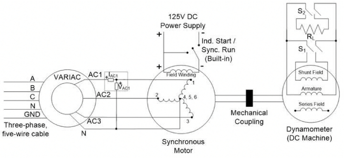
- 三相のコンセントを変圧器に配線し、図 1 に示すようにセットアップを


スキップ先...
このコレクションのビデオ:

Now Playing
AC 同期機の特性評価
Electrical Engineering
14.2K 閲覧数

電気の安全上の注意および基本的な装置
Electrical Engineering
144.5K 閲覧数

磁気コンポーネントの特性評価
Electrical Engineering
15.0K 閲覧数

電源基板をポール入門
Electrical Engineering
12.4K 閲覧数

DC-DC 昇圧コンバーター
Electrical Engineering
56.7K 閲覧数

DC/DC 降圧コンバーター
Electrical Engineering
21.1K 閲覧数

フライバックのコンバーター
Electrical Engineering
13.2K 閲覧数

単相変圧器
Electrical Engineering
20.1K 閲覧数

単相整流器
Electrical Engineering
23.4K 閲覧数

サイリスタ整流器
Electrical Engineering
17.4K 閲覧数

単相インバーター
Electrical Engineering
17.9K 閲覧数

DC モータ
Electrical Engineering
23.3K 閲覧数

AC 誘導モータ特性
Electrical Engineering
11.6K 閲覧数

VFD 給電 AC 誘導機
Electrical Engineering
6.9K 閲覧数

AC 同期機同期
Electrical Engineering
21.5K 閲覧数
Copyright © 2023 MyJoVE Corporation. All rights reserved