Aby wyświetlić tę treść, wymagana jest subskrypcja JoVE. Zaloguj się lub rozpocznij bezpłatny okres próbny.
Method Article
Wastewater Irrigation Impacts on Soil Hydraulic Conductivity: Coupled Field Sampling and Laboratory Determination of Saturated Hydraulic Conductivity
W tym Artykule
Podsumowanie
Here we present a methodology which matches a soil sample size and a hydraulic conductivity measurement device to prevent the so-called wall flow along the inside of the soil container from being erroneously included in water flow measurements. Its use is demonstrated with samples collected from a wastewater irrigation site.
Streszczenie
Since the early 1960s, an alternative wastewater discharge practice at The Pennsylvania State University has been researched and its impacts monitored. Rather than discharging treated wastewater to a stream, and thereby directly impacting the stream quality, the effluent is applied to forested and cropped land managed by the University. Concerns related to reductions in soil hydraulic conductivity occur when considering wastewater reuse. The methodology described in this manuscript, matching soil sample size with the size of the laboratory-based hydraulic conductivity measurement apparatus, provides the benefits of a relatively rapid collection of samples with the benefits of controlled laboratory boundary conditions. The results suggest that there may have been some impact of wastewater reuse on the soil's ability to transmit water at deeper depths in the depressional areas of the site. Most of the reductions in the soil hydraulic conductivity in the depressions appear to be related to the depth from which the sample was collected, and by inference, associated with the soil structural and textural differences.
Wprowadzenie
Discharge of treated wastewater from municipalities into streams has been a standard practice for decades. Such wastewater is treated primarily for the purpose of reducing the potential for biological oxygen consumption by microorganisms in the receiving waters, as a result of the discharged wastewater effluent. Oxygen consumption by microorganisms degrades organic materials in the wastewater reducing the oxygen levels in the water body into which the effluent is discharged and thereby harm aquatic organisms, including fish.
In recent decades concerns have developed related to inorganic nutrients, some metals, and other chemicals within wastewater which create harm. Due to a study published by Kolpin et al.1, a greater focus on a range of chemicals not previously considered has evolved. This study, published by the United States Geological Society, raised awareness regarding the wide range of personal care products and other chemicals in rivers and streams across the US due to discharge from wastewater treatment facilities.
Since the early 1960s, researchers at Penn State University have investigated and developed an alternative wastewater discharge practice somewhat unique in a humid region. Rather than discharging treated wastewater to a stream, and thereby directly impacting the stream quality, the effluent is applied to the forested and the cropped land managed by the University. This application area, nicknamed "The Living Filter", presently accepts all wastewater effluent generated from the campus plus some from the municipality. This reduces the likelihood for excess nutrients to enter streams which deliver water to the Chesapeake Bay, protects the local cold-water fishery from discharges of warm wastewater which is harmful to the fish, and prevents the delivery of other chemicals contained in the wastewater from directly contacting aquatic ecosystems.
However, there are always consequences of behavior changes, and this alternative use facility is not immune to such. Questions have arisen regarding whether the application of the wastewater effluent has negatively impacted the soil's ability to allow water to infiltrate the soil surface2,3,4,5 and caused greater runoff, whether there is a possible contamination of the local wells with chemicals (nutrients, antibiotics or other pharmaceutical compounds, personal care products) contained in the wastewater effluent, and whether those chemicals are creating negative environmental impacts, such as through the uptake of chemicals into plants6 grown on the site, or the development of antibiotic resistance in soil organisms7 at the site.
As a result of some of these concerns, this study is conducted to determine the impacts of the irrigation of wastewater effluent on soil hydraulic conductivity at saturation. The approach used involves collecting soils from selected sites either within or outside the irrigated area and matching the soil sample container size with the laboratory setup. It is important for the soil sample container to fit into the laboratory apparatus and for the water that moves downward through the soil matrix in the sample to be separated from the water that moves downward between the soil and the soil sample container. The protocol describes how the laboratory apparatus is constructed to ensure this occurred.
Soil samples are collected using a hydraulic core sampler attached to a tractor. Soil cores are collected from selected areas in the undulating landscape and retained in a plastic sleeve fitted into the soil core sampler. These cores are collected from a Hagerstown silt loam, located either in a summit landscape position or in a depressional area. Six representative summits and six depressional sites are sampled from the irrigated area (a total of 12 irrigated area sampling sites). In addition, three summits and three depressional sites are sampled from an adjacent, non-irrigated area (a total of six non-irrigated sites). A maximum of six cores is collected at each site to a maximum depth of approximately 1,200 mm, with each core sample being approximately 150 mm long (100 mm of the sample being contained in the plastic sleeve and 50 mm being contained in the cutting head of the metal sampler). After removal from the metal sampler, the plastic sleeves containing the collected soil cores are fitted with end caps, transported upright to the laboratory, and stored upright until they are used to determine the saturated hydraulic conductivity. Concurrently, soil samples are collected at each depth for the determination of soil and soil solution concentrations of Calcium (Ca), Magnesium (Mg), and Sodium (Na) using a Mehlich 3 extraction for estimates of soil concentrations8 and deionized water extracts at a 1:2 ratio of soil mass:water mass. The chemical analyses of the water extracts were obtained from Inductively Coupled Plasma Atomic Emission Spectroscopy (ICP-AES) and were used to calculate the Sodium Adsorption Ratio (SAR).
The determination of the saturated hydraulic conductivity is carried out primarily using a constant head method9. A solution containing Ca and Na salts to mimic the effluent electrical conductivity (EC) and SAR of the effluent is created so the soil will be exposed to water quality variables similar to the wastewater applied in the field. In this case, the EC is 1.3 dS/m and the SAR is 3, reflecting the EC and SAR of the effluent in recent years prior to the sample period. [Technically, the units for SAR are (milliequivalents/liter)½ and are not usually identified in the literature.]
The modification to the constant head method of Klute and Dirksen9 is the development of a flow separator by Walker8 to prevent flow through the column which occurred outside the soil matrix from being included in the estimate of the soil hydraulic conductivity. The flow separator is built using polyvinyl chloride (PVC) tubing selected and machined to match the soil sample size. A screen supports the soil sample and allows the water that has moved through the soil matrix to flow out the bottom of the sample. A second outlet emits the water that has flowed down the inside of the plastic sleeve, thereby eliminating so-called "wall flow" from being incorrectly included in the estimate of the amount of water that moves through the soil matrix.
Protokół
1. Selecting Soil Sampling Locations
- Identify through aerial photography and site visit(s) locations that have received irrigation by wastewater and those that have not.
- Select several representative sites from which to sample, paying close attention to possible landscape differences (particularly landscape location, such as summit, side slope, toe slope, and depression) on which water, soil, and plants may interact differently.
- Identify portions of the landscape as a summit, side slope, toe slope, or depression. Categorize the representative sites based on their major characteristics.
NOTE: In this experiment, sites were identified as a non-irrigated summit, irrigated summit, non-irrigated depression, or irrigated depression. - Determine the number of locations and the site of each location from which samples will be taken from each distinctive representative site.
NOTE: Often, discussions with a statistician familiar with environmental statistics will be very helpful at this point and prevent later concerns regarding statistical analyses. - Place a marking flag at each planned sample location and record the location of the planned sample sites on a map, using GPS coordinates.
2. Collecting Soil Samples
- Determine the equipment that will be used to collect the soil samples.
NOTE: For shallow (e.g., less than 300 mm deep) soil samples, a cylindrical soil sampler (Supplementary Figure 1) of the size used for this experiment can often be driven into the soil with a drop hammer, if the soil is soft enough. For the experiment described here, a hydraulic drill rig was used to allow samples to be collected from depths up to 1,200 mm.

Supplemental Figure 1: Drill rig used for sampling.
- Transport the drill rig to the site to conduct the sampling.
- Put on hard hats, gloves, and protective goggles prior to starting the drill rig.
- Power up the drill rig and lower the rotary head sufficiently to allow the installation of the Kelly bar.
NOTE: The Kelly bar is the metal rod that connects the drive head of the drill rig to the sampler. - Insert the Kelly bar into the rotary head.
- Insert a plastic liner/sample tube into the metal sample tube with a cutting head attached to the bottom of the metal sample tube. For the application described here, use a 150 cm long and 90 mm outside diameter (OD) plastic liner fitted into a 200 mm long and 100 mm OD/90 mm inside diameter (ID) metal sample tube.
- Attach the metal sample tube to the Kelly bar using a drive head fitted to both.
- Operate the drill rig to move the sample tube approximately 150 mm into the soil.
NOTE: This will provide a 100 mm sample in the plastic liner and allow for a 50 mm space at the top of the sample to hold water ponded on the sample when the saturated hydraulic conductivity measurements are obtained in the laboratory. This will also help avoid compacting the soil sample during its collection. - Remove the metal sample tube from the soil using the hydraulic system of the drill rig.
- Remove the metal sample tube from the drive head. Then remove the plastic sample tube holding the soil sample from the metal sample tube, using care not to lose soil from inside the plastic sample tube, and not to compact the soil or squeeze the sides of the plastic sample tube.
- Place the end caps on each end of the plastic sample tube, using red for the end at the top of the soil sample and black for the bottom of the soil sample. Tape the end caps to the sleeve to avoid contamination or the loss of water from the sample.
- Place the sample standing upright for transport back to the laboratory.
- Continue sampling to the deepest depth of interest, repeating steps 2.6–2.12.
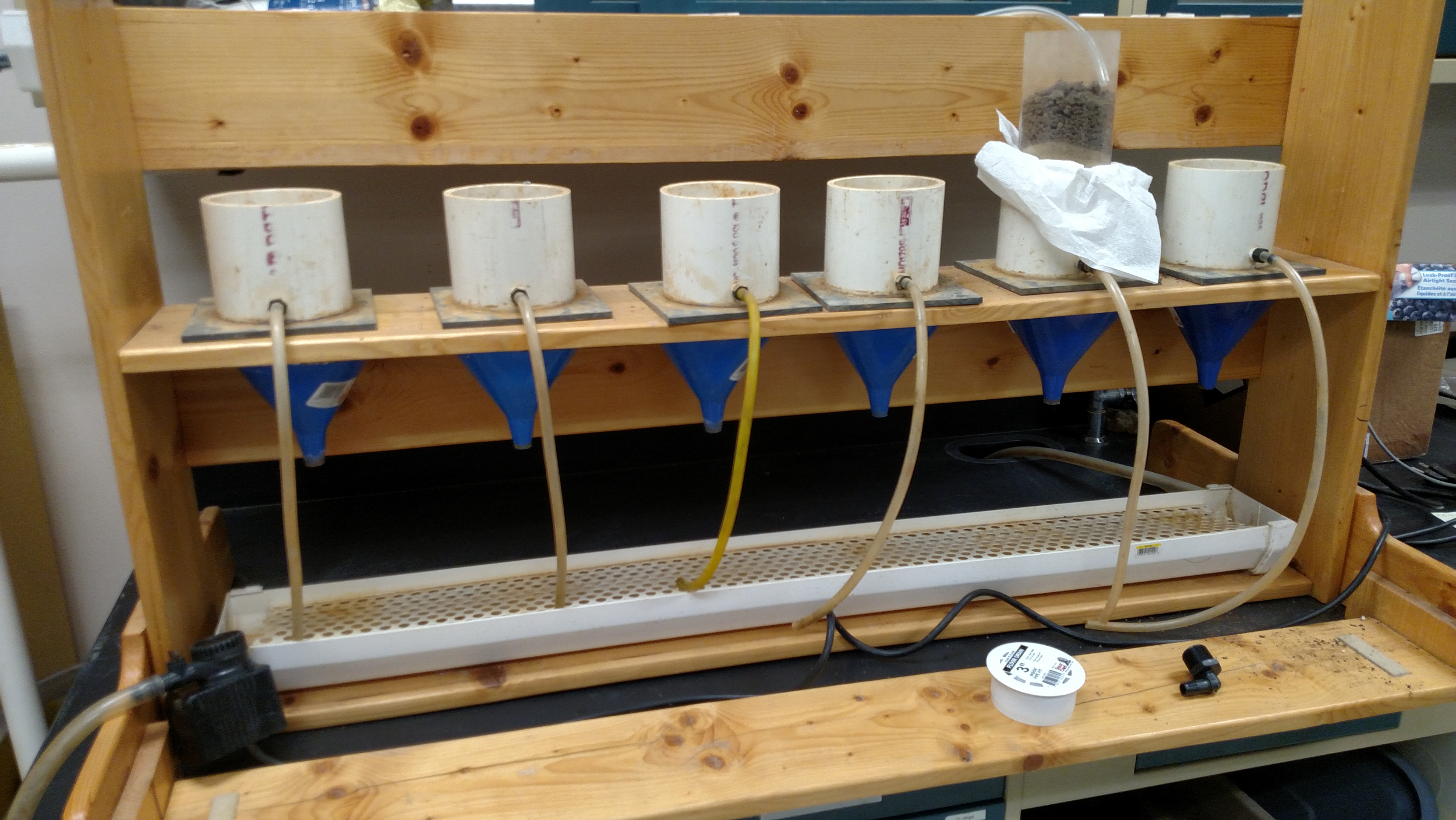
3. Building a Constant Head, Multiple Column, Soil Hydraulic Conductivity Setup
NOTE: The hydraulic conductivity laboratory apparatus is based on work by Walker10. It involves the use of a permeameter which is constructed to separate the flow in between the outer edge of the sample and the cylinder containing the ring from the flow through the soil matrix. The ID of any PVC pipe referred to below is not a strict tolerance. Some may fit well, and others may require some work (light sanding).
- Obtain a 100-mm long, 96 mm ID/114 mm-OD schedule 40 PVC pipe.
- Obtain a 100-mm long, 73 mm ID/89 mm-OD schedule 40 PVC pipe and machine it to have a 5 mm tapered cutting edge. Provide this with an 89 mm plastic liner to fit over the outer diameter.
- Cut off the bottom 20 mm of the schedule 40 PVC pipe referred to in step 3.2 and retain it for later use.
- From a 6 mm thick sheet of gray PVC, cut a 155 x 155 mm2. Machine the square to contain a circular opening of 60–70 mm in the center of the square.
- Cut a 6 mm thick slice of a 73 mm OD/63 mm ID schedule 40 PVC pipe.
NOTE: A 73 mm shower drain which fits within a 73 mm ID schedule 40 PVC pipe can be cut and works well if a 73 mm OD schedule 40 PVC pipe is not available. - Using PVC cement, attach the 6 mm thick slice of 73 mm OD PVC (from step 3.5) 20 mm below the top of the 89 mm OD PVC (from step 3.2).
- After the PVC cement used in step 3.6 has dried, center the two PVC cylinders onto the 6 mm sheet and attach them to the sheet using PVC cement.
- Drill a hole in the outer PVC cylinder, centered approximately 15 mm above the gray PVC square, to accommodate a 14 mm PVC adapter with a barbed end.
- Cement the adapter in place using PVC cement.
- Attach a 19 mm OD/13 mm ID plastic tubing to the barbed end of the adapter.
- Cement the 20 mm piece of the schedule 40 PVC referred to in step 3.4 to the bottom of the gray PVC square, centered on the opening.
- Cut out an 80–85 mm diameter circular piece of 6 mm x 18 G wire mesh (a galvanized steel gutter guard works well for this) to insert into the 89 mm OD PVC from the top so that it rests on the 6-mm thick slice of the 73 mm OD PVC.
- Select a 19 x 184 x 2,438 mm3 board, and cut it in half, trimming each length to 1,180 mm.
- Cut out 6–125 mm holes spaced 70 mm apart in the board.
- Place a wire mesh under the holes in the board and attach it (e.g., using a staple gun).
- Place a 140 mm (top opening) x 19 mm (spout OD) funnel below the wire mesh and attach it to the board; placing adhesive caulk on the rim of the funnel to eliminate gaps between the top of the funnel and the wood.
- Build a 750 mm high wooden frame to hold the board with the 6 holes (see steps 3.13 and 3.14) approximately 350 mm above the bottom of the frame.
- Prepare the components of this frame to include a base, two frame ends, two stabilizing legs, a lower strengthening base, a stabilizing base, a center-stabilizing back board, and a top back board.
- Cut a board to 19 x 184 x 1,180 mm3 as the base.
- Cut two boards to 19 x 184 x 750 mm3 each as frame ends.
- Cut two boards to create a 19 x 184 x 600 mm3 stabilizing leg on each end.
- Cut a board to 19 x 184 x 1,180 mm3 to serve as a lower strengthening base directly beneath the board with the 125 mm holes drilled in it (see step 3.14).
- Cut a board to 19 x 184 x 1,219 mm3 as a stabilizing base attached to the front or rear of the two stabilizing legs.
- Cut a board to 19 x 184 x 1,219 mm3 as a center stabilizing back board.
- Cut a board to 19 x 184 x 1,219 mm3 as a top back board to add additional stability, onto which a gutter will be attached.
NOTE: The top back board and attached gutter should be at a height such that the bottom of the gutter is approximately at the same elevation as the top of the soil in the soil sample sleeve will be when the sample is in place.

Supplemental Figure 2: Front view of saturated hydraulic conductivity apparatus. Please click here to view a larger version of this figure.
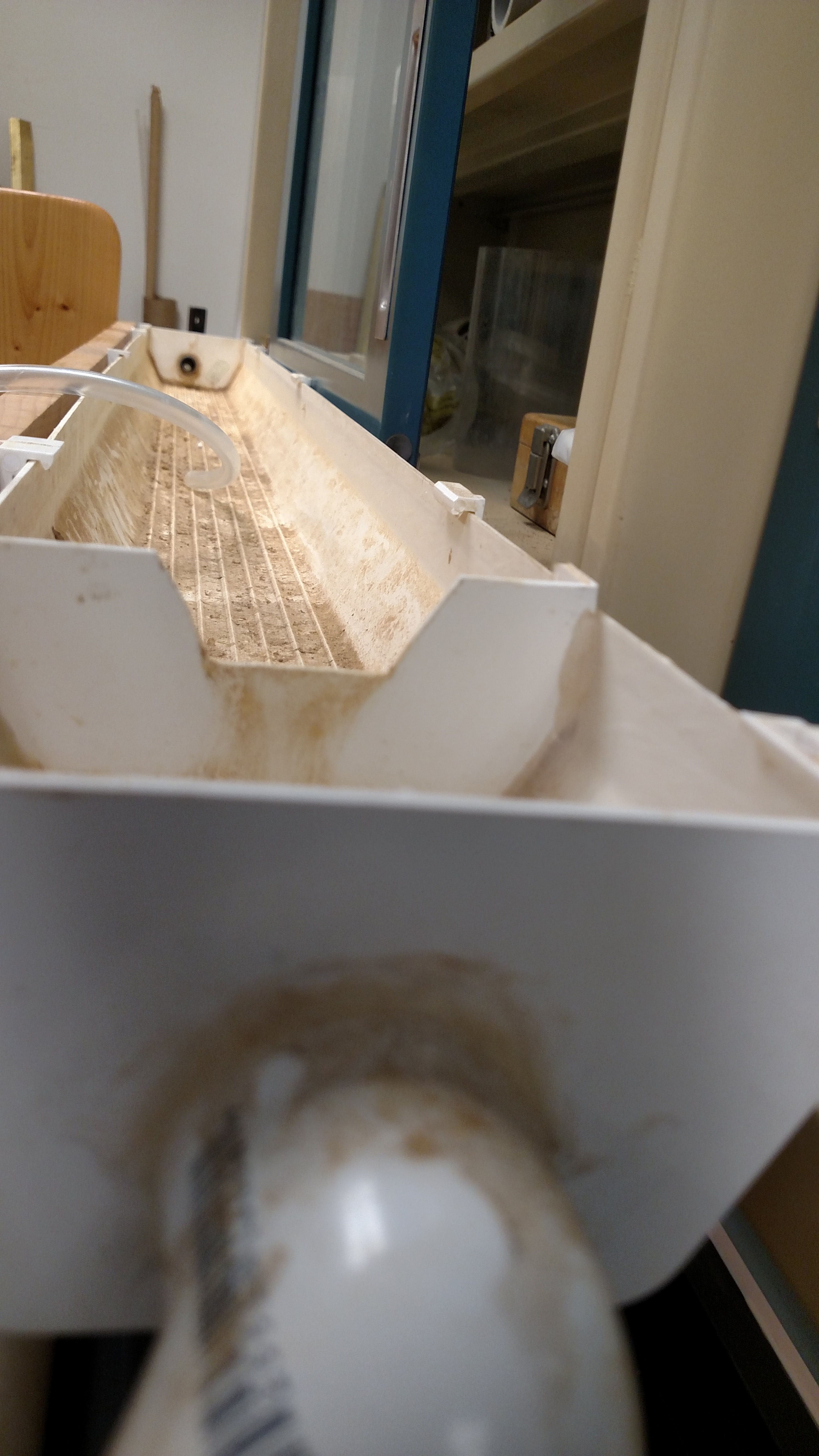
- Prepare the supply and drainage gutters.
NOTE: Each plastic gutter is approximately 120 mm across and 1219 mm long and is fitted with end caps.- Drill holes in one end cap of the drainage gutter and in one end of the supply gutter to accommodate a 13 mm HB x MGHT nylon barbed end adapter in each hole.
- Drill holes in the other end cap of the supply gutter to accommodate a 25 mm ID PVC pipe to allow for drainage back to the supply container.
- Cement the angled PVC connections as needed to allow for drainage of water back to the supply container.
- Cut a 40 mm high gutter end cap to fit inside the supply gutter approximately 10 cm from the PVC-connected outlet.
- Cut a trapezoidal notch at the top of that end cap which is approximately 20 mm deep, 30 mm wide at the bottom and 50 mm wide at the top of the notch.
NOTE: This will act to maintain a constant head in the supply gutter. - Place the drainage gutter underneath the funnels so it rests on the lower strengthening base of the wooden frame.
- Attach the supply gutter to the top back board using vinyl gutter hangers.

Supplemental Figure 3: End view of water supply gutter. Please click here to view a larger version of this figure.
- Prepare the water source.
- Connect the plastic tubing to the nylon barbed end adapters in both the supply gutter and the drainage gutter.
- Place a large tub on the floor adjacent to the conductivity device set up to serve as the supply container.
NOTE: The tub should be selected to hold enough water for at least 24 h of measurements. - Place a small submersible pump into the tub and connect it via plastic tubing to the inlet end of the supply gutter.
- Connect the small plastic tubing to the barbed end adapters of the wall flow outlet (referred to in 3.9) and place the non-connected end of the tubing into the drainage gutter.
- Fill the supply container with water.
- Plug in the pump and run it to fill the supply gutter. Ensure the rate of water being pumped into the supply gutter is adequate to keep the supply gutter nearly full without overflowing.
- Prepare a "practice soil sample" to identify any modifications needed.
- Place a "practice" soil sample into a plastic sampling sleeve, leaving about 50 mm of space between the top of the soil and the top of the plastic sleeve.
- Cover the lower end of the sample and sleeve with a double layer of cheesecloth. Hold the cheesecloth on the sampling sleeve with a sufficiently sized rubber band.
- Place the practice soil sample and sleeve into a tub of water filled to about 1/3 of the height of the sleeve, with the cheesecloth end being in the water.
- After several hours, raise the water in the tub to approximately 2/3 of the height of the sample. After allowing the sample to set overnight, fill the tub to just below the top of the soil sample (NOT the top of the sleeve).
- Place the soil sample on top of the 89-mm OD PVC tube and gently press it onto the tube, allowing the sharpened edge of the PVC tube to press into the soil a few millimeters to permit the bottom of the soil to rest on the screen.
NOTE: The cheesecloth will need to have the rubber band loosened in order to permit this. Also, note that the top of the soil in the sample sleeve should be approximately level with the bottom of the supply gutter and the top of the sample sleeve should be approximately level with the top of the supply gutter. - Provide water to the top of the soil sample.
- Turn on the pump and fill the supply gutter.
- Ensure the end of the drainage tube is placed in the drainage gutter and the outlet from the drainage gutter is tightly connected to the plastic tubing which is placed into a drain or container at a lower elevation.
- Using 6-mm tubing, create a siphon from the supply gutter to the top of the soil.
- Collect water samples from the soil core which drains from the funnel.
NOTE: Samples should be collected for the length of time needed to obtain sufficient water in order to have the precision required for the experiment, based on research criteria. - Check for leaks or unanticipated problems.
- Determine the approximate length of time needed to collect an adequate amount of water based on the time needed to fill approximately half a 100 mL beaker with water (or other volume determined by the research team).
- Create a simulated "wall flow" by inserting a small screwdriver or another similar implement along the inside of the plastic soil sample container to confirm that the excess flow created by this passageway does flow to the drainage gutter through the drainage tube.
- Modify the setup based on any problems found in this practice run.
4. Obtaining Soil Hydraulic Conductivity Values
- Wet up the soil samples which were collected from the field site by covering the bottom ends of the samples with cheesecloth held in place with a rubber band, following the directions provided in step 3.20 for the practice run.
- Start the pump and allow the supply gutter to fill. Check for leaks.
- Place the samples onto the hydraulic conductivity device as done for the practice run. Be careful not to compact the samples during handling.
- Set up the siphon tubes to move water from the supply gutter onto the surface of the soil contained in the plastic sleeve.
- Initially, begin to collect water from the funnel every 10–20 min, to gain an idea of how long to take samples and how frequently to take samples. Record times and water masses/volumes at each sample time for each soil sample.
- Look for sequential samples to contain equal amounts of water. After 3–5 samples contain the same amount of water, the sample has likely reached a steady state.
NOTE: To ensure the steady state has been reached, it may be desirable to take a couple additional samples scheduled 1 h apart. - Use Darcy's law to calculate the saturated hydraulic conductivity;

where
Ksat = saturated hydraulic conductivity (L/T)
V = steady state volume of water flowing through the core (L3)
L = sample length (L)
A = sample cross-section area of the core (L2) through which water is flowing. For this setup,

T = time (T)
(H2 – H1) = hydraulic head difference (L); for this setup, it is the distance between the top of the water ponded on the soil surface and the bottom of the soil sample.
Wyniki
To investigate the question of whether the application of wastewater effluent at the Living Filter site has impacted the ability of the soil to transmit water, we conducted experiments to measure the saturated hydraulic conductivity of the soils. We compared hydraulic conductivity of soils from irrigated areas of the site with those in non-irrigated areas of the site. The impact of wastewater effluent on the soil hydraulic conductivity is a question of concern, as there have been some rep...
Dyskusje
The ability to collect field-based, undisturbed soil samples and obtain their hydraulic conductivity values is important in obtaining data representative of a site. In order to best represent field conditions, it is important to use soil samples which remain in a physical state representative of their environment in the field. Soil samples collected from a field site which are then disturbed by subsampling or by handling induced compaction, for example, will experience structural changes which impact the saturated hydrau...
Ujawnienia
The authors have nothing to disclose.
Podziękowania
The authors would like to thank the Pennsylvania State University Office of Physical Plant for providing partial funding to support this project. Partial funding was also provided by the USDA-Regional Research Project W-3170. We would like to express our gratitude to Ephraim Govere for his assistance with the analytical work. Our deepest gratitude is to Charles Walker, whose engineering design and construction skills made it possible for us to conduct this work.
Materiały
| Name | Company | Catalog Number | Comments |
| Sampling equipment: | |||
| Soil Sampler Drill Rig | Giddings Machine Co. Inc | #25-TS / Model HDGSRTS | * NOTE: This model is comparable to the model we utilized but which is no longer produced |
| Kelly Bar | Giddings Machine Co. Inc | #KB-208 8 Ft. Kelly Bar | |
| Soil Sample Collection Tube | Giddings Machine Co. Inc | #ZC-180 4-3/4” X 7-1/4” | |
| Soil Collection Tube Bit | Giddings Machine Co. Inc | #ZC-190 4-3/4” Standard Relief | |
| Plastic Liner for Soil Sample | Giddings Machine Co. Inc | #ZC-208 3-5/8” x 6” | Enough for the number of samples being collected |
| Black end caps a for bottom of sample liners | Giddings Machine Co. Inc | To retain samples in liners | |
| Red end caps a for top of sample liners | Giddings Machine Co. Inc | To retain samples in liners | |
| Cooler Chest | Store & maintain samples upright in sample liners during transport from field to lab | ||
| Protective gear: | |||
| Hardhats, googles, and gloves | other items as needed for personal protection | ||
| Saw | |||
| Drill and bits | |||
| PVC Cement | |||
| 6 to 8 - 19 mm x 184 mm x 2438 mm boards | |||
| 2 – barbed fittings; 13 mm HB x MGHT | to connect plastic tubing to supply gutter and to drainage gutter | ||
| 6 – barbed fitting | to connect plastic tubing to outer PVC cylinder to allow for water drainage | ||
| 3000 mm long - 19 mm OD / 13 mm ID plastic tubing | |||
| 6 – 85 mm diameter circular mesh pieces | Can be cut from (e.g.) a 600 mm long, 6 mm x 18 gauge wire mesh (e.g. galvanized steel gutter guard) | ||
| Schedule 40 PVC pipe – 96 mm ID / 114 mm OD | |||
| Schedule 40 PVC pipe – 73 mm ID / 89 mm OD | |||
| Schedule 40 PVC pipe – 63 mm ID / 73 mm OD, OR 6 - 73 mm plastic shower drains | |||
| Schedule 40 PVC pipe – 25 mm ID | |||
| 6 - 6 mm thick x 155 mm square sheets of PVC | Can purchase 2 – 6 mm x 300 mm (appx) sheets for about $20 each from: https://www.interstateplastics.com/Pvc-Gray-Sheet-PVCGE~~SH.php?vid=20180212222911-7p | ||
| 6 – 140 mm by 19 mm plastic funnels | To direct water flowing from soil sample into collection beaker | ||
| Adhesive caulk | |||
| 1 – length of 150 mm x 1200 mm wire mesh cloth | 4 Mesh works well | ||
| 2 – 120 mm x 1219 mm plastic gutter with end caps | |||
| 4 – gutter hangers | |||
| 1 - additional gutter end cap | To be cut as described in procedures to create a constant head in the supply gutter | ||
| 1 – large plastic tub | Appx 65 L in volume, for example, to serve as water source for the hydraulic conductivity procedure | ||
| 1 – large plastic tub | To serve for wetting up soil samples | ||
| 1 – Submersible pump | e.g. Beckett M400 AUL or M400 AS | ||
| Plastic tubing | Various sized drainage tubes, water supply tube, and drain from drainage gutter | ||
| Container of Cheese Cloth | To place at bottom of soil sample help retain soil in plastic sample container during hydraulic conductivity and wetting up | ||
| Rubber bands | Large enough to fit around plastic sample liners tightly | ||
| Scale which measures to at least 0.1 gram | |||
| Beaker or other container to collect water from each sample | |||
| Sodium Chloride | For creating a water quality similar to that which is typically applied to the soil | ||
| Calcium Chloride | For creating a water quality similar to that which is typically applied to the soil |
Odniesienia
- Kolpin, D. W., et al. Pharmaceuticals, hormones, and other organic wastewater contaminants in U.S. streams, 1999-2000: a national reconnaissance. Environmental Science & Technology. 36 (6), 1202-1211 (2002).
- Duan, R., Sheppard, C. D., Fedler, C. B. Short-term effects of wastewater land application on soil chemical properties. Water, Air, & Soil Pollution. 211 (1-4), 165-176 (2010).
- Frenkel, H., Goertzen, J. O., Rhoades, J. D. Effects of clay type and content exchangeable sodium percentage, and electrolyte concentration on clay dispersion and soil hydraulic conductivity. Soil Science Society of America Journal. 42 (1), 32-39 (1978).
- Goncalves, R. A. B., et al. Hydraulic conductivity of a soil irrigated with treated sewage effluent. Geoderma. 139 (1-2), 241-248 (2007).
- Halliwell, D. J., Barlow, K. M., Nash, D. M. A review of the effects of wastewater sodium on soil physical properties and their implications for irrigation systems. Australian Journal of Soil Research. 39 (6), 1259-1267 (2001).
- Franklin, A. M., Williams, C. F., Andrews, D. M., Woodward, E. E., Watson, J. E. Uptake of Three Antibiotics and an Antiepileptic Drug by Wheat Crops Spray Irrigated with Wastewater Treatment Plant Effluent. Journal of Environmental Quality. 45 (2), 546-554 (2016).
- Franklin, A. M., et al. Antibiotics in agroecosystems: introduction to the special section. Journal of Environmental Quality. 45 (2), 377-393 (2016).
- Wolf, A. M., Beegle, D. B., Sims, J. T., Wolf, A. Recommended soil tests for macronutrients. Recommended Soil Testing Procedures for the Northeastern United States. , 39-47 (2011).
- Klute, A., Dirksen, C., Klute, A. Hydraulic conductivity and diffusivity: laboratory methods. Methods of Soil Analysis: Part 1-Physical and Mineralogical Methods. , 687-743 (1986).
- Walker, C. . Enhanced techniques for determining changes to soils receiving wastewater irrigation for over forty years. , (2006).
- Perroux, K. M., White, I. Designs for disc permeameters. Soil Science Society of America Journal. 52 (5), 1205-1215 (1988).
- Clothier, B. E., White, I. Measurement of sorptivity and soil water diffusivity in the field. Soil Science Society of America Journal. 45 (2), 241-245 (1981).
- Ankeny, M. D., Ahmed, M., Kaspar, T. C., Horton, R. Simple field method for determining unsaturated hydraulic conductivity. Soil Science Society of America Journal. 55 (2), 467-470 (1991).
- Larson, Z. M. . Long-term treated wastewater irrigation effects on hydraulic conductivity and soil quality at Penn State's Living Filter. , (2010).
Przedruki i uprawnienia
Zapytaj o uprawnienia na użycie tekstu lub obrazów z tego artykułu JoVE
Zapytaj o uprawnieniaPrzeglądaj więcej artyków
This article has been published
Video Coming Soon
Copyright © 2025 MyJoVE Corporation. Wszelkie prawa zastrzeżone