
Thyristor Rectifier
Обзор
Source: Ali Bazzi, Department of Electrical Engineering, University of Connecticut, Storrs, CT.
Similar to diodes, thyristors, also called silicon controlled rectifiers (SCRs), pass current in one direction from the anode to cathode, and block current flow in the other direction. However, current passage can be controlled through a "gate" terminal, which requires a small current pulse to turn on the thyristor so it can start conducting.
Thyristors are four-layer devices, composed of alternating layers of n-type and p-type material, thereby forming PNPN structures with three junctions. The thyristor has three terminals; with the anode connected to the p-type material of the PNPN structure, the cathode connected to the n-type layer, and the gate connected to the p-type layer nearest the cathode.
The objective of this experiment is to study a controlled thyristor-based half-wave rectifier at different conditions, and understand how different timings of the gate pulse affect the DC output voltage.
Процедура
ATTENTION: During this experiment, do not touch any part of the circuit while energized. Do NOT ground the VARIAC.
For this experiment, the variable transformer (VARIAC) at a low frequency of 60 Hz and peak of 35 V is used as the main AC source.
1. Setup
- Before starting, connect the differential probe to one scope channel.
- Set the button on the differential probe to 1/20 (or 20X) attenuation.
- On the sc
Результаты
The AC input voltage waveform is chopped until the firing angle. Important relationships of the average output voltage and firing angles for different SCR rectifiers with input Vin= V0 cos(ωt) are:
• Single SCR and R load: <Vout>=V0[1+cos(α)]/(2π) (2)
Заявка и Краткое содержание
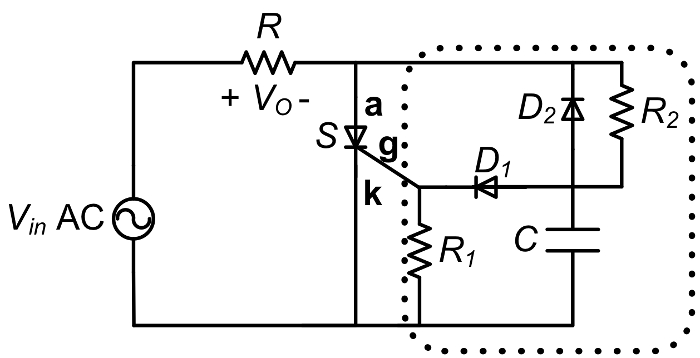
SCR's were common in older DC power supplies that required a variable DC output voltage from an AC input. By adjusting the resistor R2 in the above circuit, it is possible to adjust the average Vout and therefor an adjustable DC power supply results. SCRs are not common any more in DC power supplies as they switch at the input line frequency (typically 50 or 60 Hz), and new power supplies switch at 10 s or 100 s of kHz which makes filtering the output voltage to extract the DC
Перейти к...
Видео из этой коллекции:

Now Playing
Thyristor Rectifier
Electrical Engineering
17.6K Просмотры

Electrical Safety Precautions and Basic Equipment
Electrical Engineering
144.8K Просмотры

Characterization of Magnetic Components
Electrical Engineering
15.1K Просмотры

Introduction to the Power Pole Board
Electrical Engineering
12.5K Просмотры

DC/DC Boost Converter
Electrical Engineering
57.1K Просмотры

DC/DC Buck Converter
Electrical Engineering
21.2K Просмотры

Flyback Converter
Electrical Engineering
13.3K Просмотры

Single Phase Transformers
Electrical Engineering
20.2K Просмотры

Single Phase Rectifiers
Electrical Engineering
23.5K Просмотры

Single Phase Inverter
Electrical Engineering
18.0K Просмотры

DC Motors
Electrical Engineering
23.5K Просмотры

AC Induction Motor Characterization
Electrical Engineering
11.7K Просмотры

VFD-fed AC Induction Machine
Electrical Engineering
7.0K Просмотры

AC Synchronous Machine Synchronization
Electrical Engineering
21.6K Просмотры

AC Synchronous Machine Characterization
Electrical Engineering
14.3K Просмотры
Авторские права © 2025 MyJoVE Corporation. Все права защищены