
A subscription to JoVE is required to view this content. Sign in or start your free trial.
Method Article
Clinical Assessment of Spatiotemporal Gait Parameters in Patients and Older Adults
In This Article
Summary
This protocol is used to evaluate spatial and temporal gait variables of neurological/orthopedic patients and older persons by means of a recently-introduced floor-based photocell system.
Abstract
Spatial and temporal characteristics of human walking are frequently evaluated to identify possible gait impairments, mainly in orthopedic and neurological patients1-4, but also in healthy older adults5,6. The quantitative gait analysis described in this protocol is performed with a recently-introduced photoelectric system (see Materials table) which has the potential to be used in the clinic because it is portable, easy to set up (no subject preparation is required before a test), and does not require maintenance and sensor calibration. The photoelectric system consists of series of high-density floor-based photoelectric cells with light-emitting and light-receiving diodes that are placed parallel to each other to create a corridor, and are oriented perpendicular to the line of progression7. The system simply detects interruptions in light signal, for instance due to the presence of feet within the recording area. Temporal gait parameters and 1D spatial coordinates of consecutive steps are subsequently calculated to provide common gait parameters such as step length, single limb support and walking velocity8, whose validity against a criterion instrument has recently been demonstrated7,9. The measurement procedures are very straightforward; a single patient can be tested in less than 5 min and a comprehensive report can be generated in less than 1 min.
Introduction
Walking is one of the most important physical activities in everyday life, and is a main determinant of the quality of life for elderly and patient populations who may present with gait deteriorations. Clinical evaluation of gait function is therefore important to reveal potential alterations induced by aging and/or neurological/orthopedic pathologies, but also to prove the functional benefits of a treatment. Different instruments have been developed for the quantitative assessment of gait parameters, e.g., force plates, video-based 3D motion analysis, body-mounted accelerometers10,11, and instrumented walkway mats or treadmills12. However, these systems are mainly used for research studies rather than for clinical purposes because they are complex to operate, have low accessibility, and fragile sensors.
A floor-based photoelectric system has recently been introduced, which is able to provide a valid calculation of temporal features and 1D spatial coordinates of walking steps. This measuring instrument has several advantages compared to pre-existing systems: it is easy to handle, data are collected very quickly, it is simple to create a detailed report and it is a modular system which means that the length of the system can be changed. Thus, it can be used with confidence to measure within-group changes in longitudinal assessments and between-group differences in cross-sectional comparisons. The goals of the described protocol are to focus on the equipment and its installation, and to objectively and straightforwardly describe the assessment procedures for evaluating spatiotemporal gait parameters in elderly and patient populations.
Protocol
The protocol follows the guidelines of the local human Ethics Committee in Zurich (KEK Zurich).
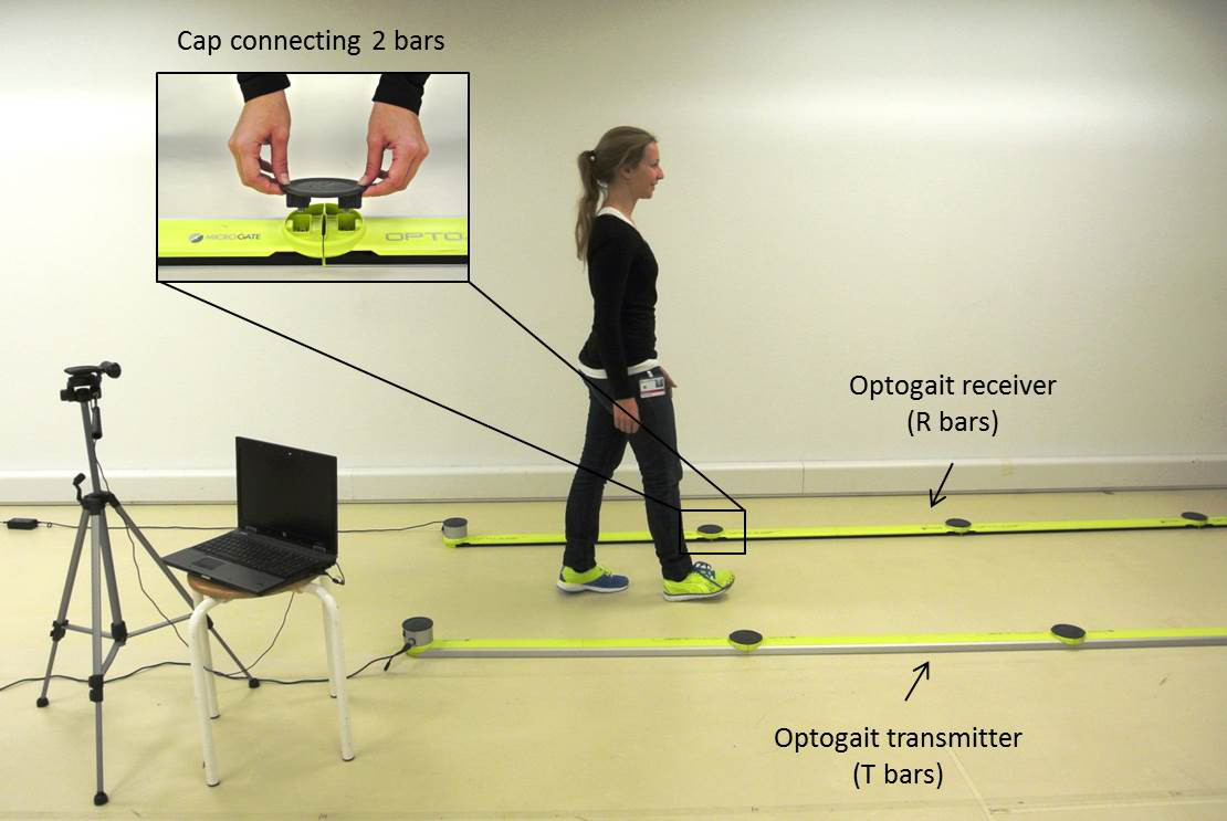
1. Hardware Installation (Figure 1)
- Use two 10-m sets of floor-based bars and place them parallel to each other (and to the line of progression) to create a corridor with an inter-set distance of approximately 1 m.
NOTE: This distance can be increased up to 8 m. Each bar has a length of 1 m and consists of 96 light diodes. - Make a distinction between light-transmitting (T) and light-receiving (R) units for the installation of the bars by placing the light-transmitting (T) units on the right side and the light-receiving (R) units on the left side with respect to the walking direction.
NOTE: The first meter bars (both T and R) have silver drums. The T and R bars disposed on the remaining 9 m are all equal and interchangeable. - Connect all bars of a row with caps (wireless). Use 2 power supplies: one for each set of bars (T and R).
- Connect the first R bar to the laptop with a USB cable.
- Position the camera next to the first bar for offline verifications (e.g., starting foot), and connect it to the laptop with a USB cable.
- Put a mark 2 m before and after the beginning and end of the track.
- Switch on the photoelectric device using the on-off switch of the first R and T bar.
- Check that the control LEDs located on all R bars are green.
NOTE: If so, the system is correctly positioned and testing can start; however, if one or more of the control LEDs are red the system is not correctly positioned and/or connected. Control all caps by checking that they are completely clicked into place and then turn the system off and on again.

Figure 1. The photoelectric system consists of light-transmitting (T) and light-receiving (R) units that are placed parallel to each other with a distance of approximately 1 m. The camera is installed close to the start area for control purposes. The laptop is connected with USB cables to the first R bar and to the camera. Please click here to view a larger version of this figure.
2. Software Installation and Preparation of a Test
- Load the software operating the photoelectric system from www.optogait.com/Support/Downloads. Note: This protocol is described by using the 1.8.1 version.
- If the software is used for the first time for gait analysis create a new test as follows (otherwise proceed to step 2.3):
- Select Test then click on Define / Modify tests. Now click on Gait test and then select Duplicate test. Click on Confirm in the pop-up window so that the test is duplicated.
- Double click on the duplicated test to modify the name (e.g., Gait Test 10 bars) and select 10 for the number of bars. Use the standard parameters for the gait test, which are presented in Figure 2. Finally, select Save to save all modifications.
- Add a new patient to the database. Select Patients, click on Insert / Modify patient, and then click on New patient to enter the data. Then Save the data.

Figure 2. Standard settings for a gait test with 10 bars, as described in the present protocol. These settings have to be defined when the photoelectric system is used for the first time. In this protocol the starting foot is not defined. The system starts measuring when the patient enters the recording area and stops measuring when the patient leaves the measuring units. Please click here to view a larger version of this figure.
3. Testing Procedures
- Always give the same instructions to the patient13.
- Instruct the patient to walk with flat-soled shoes along the 10-m walkway at two different velocities: normal (“walk at a pace that is comfortable for you”), and faster than normal (“walk at a pace that is faster than you would normally walk”).
- Ask the patient to look straight ahead during the walking trials.
- Ask the patient to initiate the first step with the same foot to better standardize the test conditions.
- Ask the patient to start walking 2 m before the first photoelectric bar and to conclude each trial 2 m after the last bar in order to maintain constant gait velocity13.
- Demonstrate one trial at normal velocity to the patient.
- Request the patient to perform three familiarization trials followed by one experimental trial at each velocity. Always complete normal velocity trials first.
- To get ready with the software, click on Test and then Execute to start the measurements with the created test.
- Select the patient by clicking on Select, choosing the patient and then clicking on Confirm.
- Select the test by clicking on Select, and choosing the test e.g., Gait Test 10 bars. Check that only this test is selected for the measurement.
- Place the camera so that it can record the entire walk. Change the position of the camera while checking the live picture on the screen of your laptop.
- Finally, click on Execute again.
NOTE: Now the software is ready to measure. As soon as the patient enters the bars, the system starts to measure and a pop-up window appears asking for the starting foot.
- Click on the appropriate foot so that the gait parameters will be correctly calculated.
NOTE: The camera records automatically once the test is started. - Save the test.
4. Data Analysis
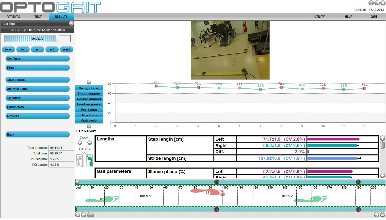
- Click on Results to display the completed trials. Then click on the arrow next to the test of interest to transfer the test from the Test list to the Test analysis section. Now click on View to display the selected test. Refer to the Results section for all tests performed in this study.
NOTE: A window with all test data appears (Figure 3). On the left side of the window there are some command buttons for activating various functions. The other part of the window presents 4 types of information regarding the current test. Each set of information can be shown/hidden using the configuration commands. From top to bottom the items are the following: video, charts displaying the results, table with numerical data, and photoelectric bars. - Click on Gait data to display a gait report (Figure 3).
- Click on Print (a window with the report appears) to print out the report.
NOTE: The report can be printed as it is or can be modified. For the different spatiotemporal parameters, the following results are presented in the report: mean values ± standard deviation (SD) of the left and right side, coefficients of variation (CV) expressing gait variability14,15, and percent difference between the left and the right side (asymmetry).- If required, modify the report as follows: open the report as described above (step 4.3). Click on the buttons Show or Hide on the left side of the screen to adapt the presented data and charts of the report.
- To change the logo and/or the footer on the report, click on the respective button (Change logo or Change footer) to modify these parameters.
- To compare two or more tests performed on different occasions, e.g., before and after an intervention, select the different tests in the results section by clicking on the arrow next to the tests and then click on the Compare button.
NOTE: A report with the direct comparison of all parameters of the different tests is displayed.

Figure 3. Screenshot of all test data. The command buttons appear on the left side of the window (e.g., by clicking on Print a report is generated, which can be eventually modified). The other part of the window presents the following information regarding the current test, from top to bottom: video, charts displaying the results, table with numerical data, and photoelectric bars. These details can be shown/hidden using the Configure button on the right side. The actual view of the data can be changed by clicking on Gait data or Gait report, respectively. Please click here to view a larger version of this figure.
Results
A recent study demonstrated the validity of the photoelectric system against a criterion instrument (a validated electronic walkway) for the assessment of spatiotemporal gait parameters in orthopedic patients and healthy elderly controls7. The same between-group differences in gait variables were detected by the two systems. Although concurrent validity was excellent, with intraclass correlation coefficients ranging between 0.933 and 0.999 (p < 0.001), a systematic bias (p < 0.001) was observed between...
Discussion
The protocol presented here can be used to evaluate spatial and temporal gait parameters of patients (orthopedic, neurological, cardiorespiratory, etc.) and healthy older adults with a recently-introduced photoelectric system. The total length and width of the system can be modulated depending on the available space and budget. The estimated cost (in Europe) is approximately 2,800 USD per meter for a 10-meter system and the minimum recommended length is 3 meter for floor-based gait analysis. A new feature of th...
Disclosures
The authors have nothing to disclose.
Materials
| Name | Company | Catalog Number | Comments |
| Optogait system (10 meters) | Microgate, Bolzano, Italy | www.optogait.com | |
| Optogait software | www.optogait.com/Support/Downloads | ||
| Laptop | |||
| The Optogait system contains the following equipment: | |||
| 10 Light-transmitting (T) bars (1 as a first meter) | |||
| 10 Light-receiving (R) bars (1 as a first meter) | |||
| 18 Caps to connect the bars within a set (9 for T and 9 for R bars) and 2 special caps for the last T and R bar | |||
| 1 Camera with its tripod | |||
| 1 Cable for connecting the Optogait to the laptop | |||
| 1 Cable for connecting the camera to the laptop | |||
| 2 Power supplies (one for each set of bars) | |||
References
- Chow, J. W., Yablon, S. A., Horn, T. S., Stokic, D. S. Temporospatial characteristics of gait in patients with lower limb muscle hypertonia after traumatic brain injury. Brain. Inj. 24, 1575-1584 (2010).
- Esser, P., Dawes, H., Collett, J., Feltham, M. G., Howells, K. Assessment of spatio-temporal gait parameters using inertial measurement units in neurological populations. Gait Posture. 34, 558-560 (2011).
- Maffiuletti, N. A., et al. Spatiotemporal parameters of gait after total hip replacement: anterior versus posterior approach. Orthop. Clin. North Am. 40, 407-415 (2009).
- Webster, K. E., Wittwer, J. E., Feller, J. A. Quantitative gait analysis after medial unicompartmental knee arthroplasty for osteoarthritis. J. Arthroplasty. 18, 751-759 (2003).
- Chui, K. K., Lusardi, M. M. Spatial and temporal parameters of self-selected and fast walking speeds in healthy community-living adults aged 72-98 years. J. Geriatr. Phys. Ther. 33, 173-183 (2010).
- Hollman, J. H., McDade, E. M., Petersen, R. C. Normative spatiotemporal gait parameters in older adults. Gait Posture. 34, 111-118 (2011).
- Lienhard, K., Schneider, D., Maffiuletti, N. A. Validity of the Optogait photoelectric system for the assessment of spatiotemporal gait parameters. Med. Eng. Phys. 35, 500-504 (2013).
- Perry, J. Gait analysis, normal and pathological function. First edn, Slack Inc. , (1992).
- Lee, M. M., Song, C. H., Lee, K. J., Jung, S. W., Shin, D. C., Shin, S. H. Concurrent validity and test-retest reliability of the OPTOGait photoelectric cell system for the assessment of spatio-temporal parameters of the gait of young adults. J. Phys. Ther. Sci. 26, 81-85 (2014).
- Item-Glatthorn, J. F., Casartelli, N. C., Petrich-Munzinger, J., Munzinger, U. K., Maffiuletti, N. A. Validity of the intelligent device for energy expenditure and activity accelerometry system for quantitative gait analysis in patients with hip osteoarthritis. Arch. Phys. Med. Rehabil. 93, 2090-2093 (2012).
- Maffiuletti, N. A., et al. Concurrent validity and intrasession reliability of the IDEEA accelerometry system for the quantification of spatiotemporal gait parameters. Gait Posture. 27, 160-163 (2008).
- Reed, L. F., Urry, S. R., Wearing, S. C. Reliability of spatiotemporal and kinetic gait parameters determined by a new instrumented treadmill system. BMC Musculoskelet. Disord. 14, 249 (2013).
- Kressig, R. W., Beauchet, O. Guidelines for clinical applications of spatio-temporal gait analysis in older adults. Aging Clin. Exp. Res. 18, 174-176 (2006).
- Dubost, V., et al. Relationships between dual-task related changes in stride velocity and stride time variability in healthy older adults. Hum. Mov. Sci. 25, 372-382 (2006).
- Hausdorff, J. M. Gait variability: methods, modeling and meaning. J. Neuroeng. Rehabil. 2, (2005).
- Blin, O., Ferrandez, A. M., Serratrice, G. Quantitative analysis of gait in Parkinson patients: increased variability of stride length. J. Neurol. Sci. 98, 91-97 (1990).
- Webster, K. E., Merory, J. R., Wittwer, J. E. Gait variability in community dwelling adults with Alzheimer disease. Alzheimer. Dis. Assoc. Disord. 20, 37-40 (2006).
- Bejek, Z., Paroczai, R., Illyes, A., Kiss, R. M. The influence of walking speed on gait parameters in healthy people and in patients with osteoarthritis. Knee Surg. Sports Traumatol. Arthrosc. 14, 612-622 (2006).
Reprints and Permissions
Request permission to reuse the text or figures of this JoVE article
Request PermissionThis article has been published
Video Coming Soon
Copyright © 2025 MyJoVE Corporation. All rights reserved