
A subscription to JoVE is required to view this content. Sign in or start your free trial.
Method Article
Controlling Particle Fraction in Microporous Annealed Particle Scaffolds for 3D Cell Culture
In This Article
Summary
Minimizing the variability in the particle fraction within granular scaffolds facilitates reproducible experimentation. This work describes methods for generating granular scaffolds with controlled particle fractions for in vitro tissue engineering applications.
Abstract
Microgels are the building blocks of microporous annealed particle (MAP) scaffolds, which serve as a platform for both in vitro cell culture and in vivo tissue repair. In these granular scaffolds, the innate porosity generated by the void space between microgels enables cell infiltration and migration. Controlling the void fraction and particle fraction is critical for MAP scaffold design, as porosity is a bioactive cue for cells. Spherical microgels can be generated on a microfluidic device for controlled size and shape and subsequently freeze-dried using methods that prevent fracturing of the polymer network. Upon rehydration, the lyophilized microgels lead to controlled particle fractions in MAP scaffolds. The implementation of these methods for microgel lyophilization has led to reproducible studies showing the effect of particle fraction on macromolecule diffusion and cell spreading. The following protocol will cover the fabrication, lyophilization, and rehydration of microgels for controlling particle fraction in MAP scaffolds, as well as annealing the microgels through bio-orthogonal crosslinking for 3D cell culture in vitro.
Introduction
Microporous annealed particle (MAP) scaffolds are a subclass of granular materials in which the microgel (µgel) building blocks are interlinked to form a bulk, porous scaffold. With the unique microarchitecture of these granular scaffolds, the innate porosity generated by the void space between interlinked spherical microgel supports accelerated cell infiltration and migration1. The microgel building blocks of MAP scaffolds can be fabricated from both synthetic and natural polymers with chemical modifications2. The methods described here specifically highlight the use of microgels comprised of a hyaluronic acid (HA) backbone modified with functional norbornene (NB) handles. The NB functional handle on the HA polymer supports click chemistry reactions for forming microgels and linking them together to generate MAP scaffolds3,4. Numerous schemes have been employed for linking the microgels together (i.e., annealing), such as enzymatic1, light-based5,6, and additive-free click chemistry3,7 reactions. Additive-free click chemistry is described in this work, using the tetrazine-norbornene inverse electron demand Diels-Alder conjugation for interlinking the HA-NB microgels.
To fabricate MAP scaffolds, users first generate the microgel building blocks using reverse emulsions either in batch systems or within microfluidic devices, as well as with electrohydrodynamic spraying, lithography, or mechanical fragmentation2. The production of spherical HA-NB microgels has been well described and previously reported using both batch emulsion2 and microfluidic droplet generation techniques8,9,10,11. In this work, spherical HA-NB microgels were generated on a flow-focusing microfluidic platform for controlled size and shape, as previously described8,9,10. After purification, the microgels exist in an aqueous suspension and must be concentrated to induce a jammed state. When jammed, microgels exhibit shear-thinning properties, which allow them to function as injectable, space-filling materials1. One method of inducing a jammed state is to dry the microgels via lyophilization, or freeze-drying, then subsequently rehydrate the dried product in a controlled volume12. Alternatively, excess buffer can be removed from the microgel slurry via centrifugation over a strainer or with manual removal of the buffer from the microgel pellet either by aspiration or using an absorbent material. However, using centrifugation to dry the microgels can generate a highly variable range of particle fractions and void fractions when making granular scaffolds12. Techniques for lyophilizing microgels have been described using 70% IPA for polyethylene glycol (PEG) microgels13, fluorinated oils for gelatin methacryloyl (GelMa) microgels14, and 70% ethanol for HA microgels12. This protocol highlights methods for freeze-drying spherical HA microgels using 70% ethanol, a standard laboratory reagent, to retain the original microgel properties during the drying process. The freeze-dried HA microgels can be weighed and rehydrated at user-defined weight percentages to control the final particle fractions in MAP scaffolds12.
The final step in MAP scaffold formation relies on annealing the microgels to create a bulk, porous scaffold1. By utilizing native extracellular matrix components and employing bio-orthogonal annealing schemes, MAP scaffolds serve as a biocompatible platform for both in vitro cell culture and in vivo tissue repair3. Through these approaches, MAP scaffolds can be fabricated from HA-NB building blocks with user-defined particle fractions for their employment in tissue engineering applications12. The following protocol describes the microfluidic production of HA-NB microgels followed by lyophilization and rehydration for controlling particle fraction in MAP scaffolds. Lastly, steps for annealing the microgels are described using bio-orthogonal chemistry for in vitro 3D cell culture experiments.
Protocol
1. Microfluidic device fabrication
- Soft lithography
NOTE: This protocol describes device fabrication of a flow-focusing microfluidic device design from de Wilson et al.9. However, this protocol can be used with any device design on an SU-8 wafer. The wafer can be taped to a Petri dish, and then needs to be silanized to prevent adherence of the PDMS to the wafer features15.- Mix the polydimethylsiloxane (PDMS) elastomer base with the curing agent (see Table of Materials) at a 10:1 ratio. Prepare approximately 100 g to cover the wafer with ~5 mm PDMS. Pour the PDMS mixture onto the wafer and degas in a desiccator for approximately 30 min. Once all the bubbles are gone, place in an oven at 60 °C for at least 2 h to cure the PDMS.
- Use a knife to gently trace around the parameter of the device without cracking the wafer; then, carefully peel the PDMS off the wafer. Use a 1 mm biopsy punch (see Table of Materials) to create the inlet and outlet channels.
NOTE: Be gentle when punching the microfluidic device. Tears or rips around the inlet or outlet channels can cause leaks during microgel production. - Use tape to remove dust from the device on the feature side. Place the devices and clean glass slides on a hot plate at 135 °C for at least 15 min to remove moisture.
- In a fume hood, use a corona plasma gun (see Table of Materials) on high on both the glass slides and devices (feature side exposed) for approximately 30 s, and then quickly bond them together. Gently apply pressure to ensure a good seal between the device and the glass slide. Place the devices in a 60 °C oven overnight to secure the bond.
2. Microfluidic production of hyaluronic acid (HA) microgels with norbornene (NB) functional handles
- HA-NB synthesis
NOTE: HA-norbornene (HA-NB) synthesis was adapted from Darling et al.3 using 79 kDa sodium HA with molar equivalents of 1:1.5:2.5 of HA-repeat units to 4-(4,6-dimethoxy-1,3,5-triazin-2-yl)-4-methylmorpholinium chloride (DMTMM) to 5-norbornene-2-methylamine (NMA).- Weigh the reactants. Dissolve the HA at 20 mg/mL in 200 mM MES buffer (pH ~6) by stirring in a beaker or flask on a stir plate. Once dissolved, add the DMTMM to the HA solution and allow to react for approximately 20 min at room temperature. For example, 1 g HA + 1.09 g DMTMM + 845 µL NMA can be used.
- Add NMA dropwise to the HA/DMTMM solution. Add parafilm to the opening of the reaction vessel to minimize evaporation and cover the reaction vessel with foil. Continue stirring while allowing the reaction to proceed for approximately 24 h.
- After 24 h, chill 200 proof ethanol (approximately 10x the reaction volume). On a stir plate, transfer the reaction dropwise to the chilled ethanol to precipitate the HA-NB and continue stirring at 200-300 rpm for 20 min.
- Transfer the solution to 50 mL conical tubes, and then centrifuge at 5,000 x g for 10 min. Pour off the excess ethanol to dispose as waste. At this point, the HA-NB product should be white pellets in the conical tubes. Pull vacuum on the HA-NB in a dessicator to dry overnight.
- Purify the HA-NB using 12-14 kDa molecular weight cut-off cellulose dialysis tubing (see Table of Materials). Dissolve HA-NB in 2 M NaCl solution and transfer to the dialysis tubing. Tie the tubing and secure with clamps, if needed. Transfer the filled dialysis tubing to a bucket with 5 L of ultrapure water and dialyze the HA-NB against water overnight.
- The next day, remove the water and replace with 1 M NaCl solution for 30 min. Remove the NaCl solution, and then dialyze against ultrapure water for 3 days, replacing the water daily.
- Filter the dialyzed product using 0.2 µm vacuum-driven filter, and then transfer the filtered product to 50 mL conical tubes.
- Add liquid nitrogen to a cryogenic container and flash-freeze the HA-NB tubes for 10 min. Then, remove the conical tubes with forceps and quickly remove the cap and cover with a lab-grade tissue (see Table of Materials). Secure the tissue with a rubber band and transfer to a lyophilization container or chamber (see Table of Materials) and lyophilize. Store the lyophilized product at -20 °C.
CAUTION: Liquid nitrogen is a hazardous substance. Wear the appropriate personal protective equipment when working with liquid nitrogen. - Quantify norbornene modification by dissolving the HA-NB at 10 mg/mL in D2O and analyzing via proton NMR (Figure 1A)16.
- To determine the amount of functionalization, first calibrate the D2O solvent peak to 4.8 PPM. Integrate the peak for the HA methyl protons (δ2.05) and calibrate the integration to 3.0. Next, integrate the peaks for the pendant norbornene groups at δ6.33 and δ6.02 (vinyl protons, endo). Normalize the integration of these peaks to the corresponding number of protons to determine the average degree of modification3.
- Preparation of HA-NB microgel precursor
- Prepare 50 mM HEPES buffer (pH 7.5) and sterile filter the buffer using a 0.2 µm vacuum-driven filter. Using the HEPES buffer, prepare respective 50 mM stocks of lithium phenyl(2,4,6,-trimethylbenzoyl)phosphinate (LAP) photo-initiator and tris(2-carboxyethyl)phosphine (TCEP) reducing agent. Keep the LAP solution away from light.
- Prepare the other microgel precursor components by preparing respective 50 mM stocks of di-thiol linker and RGD peptide in sterile distilled water. Weigh out HA-NB and dissolve in HEPES buffer to prepare a 10 mg/mL stock.
NOTE: Different di-thiol linkers could be used for the internal crosslinking of the microgels based on user preference. Both a degradable (i.e., MMP-cleavable) and non-degradable (dithiothreitol or DTT) linker have been listed in the Table of Materials. The RGD peptide is included in the microgel formulation to promote cell adhesion in MAP scaffolds, but this component could be removed and replaced with equal volume of HEPES buffer. - Combine the precursor components with final concentrations of 9.9 mM LAP, 0.9375 mM TCEP (4 thiol/TCEP), 2.8 mM di-thiol linker, 1 mM RGD peptide, and 3.5 wt% (w/v) HA-NB by adding extra HEPES buffer to reach the desired final volume. Mix the precursor well using a positive displacement pipette.
- Using a P1000 pipette, slowly pull up the entire mixture. Put the tip onto the end of a 1 mL syringe and eject the tip from the pipette. Pull the syringe plunger to load the mixture into the syringe, and then add a 0.2 µm filter on the end of syringe and filter into a new 1.5 mL microcentrifuge tube. Centrifuge the filtered precursor solution to remove the bubbles produced during filtering.
- Again, using a P1000 pipette, slowly pull up the filtered precursor being careful not to create bubbles. If there are bubbles, gently tap the tip for them to dislodge and float to the top.
- Place the tip onto the end of a 1 mL syringe and eject the tip from the pipette. Keep the syringe vertical and pull the syringe plunger slowly until the entire precursor solution is in the syringe. Add a blunt tip needle to the syringe and push the precursor through the tip of the needle. Wrap the syringe in foil to keep out of light.
- Preparation of microgel pinching solution
- Prepare 5% v/v Span-80 in heavy white mineral oil and mix well. Desiccate to remove bubbles. Keep the surfactant/oil mixture at room temperature wrapped in foil. Mix well and desiccate prior to each use.
- Use a 5 mL syringe to draw up the oil/surfactant mixture (minimize bubbles) until the distance between the plunger and the fingerhold is approximately equal to the distance of the precursor syringe. Add a blunt needle to the syringe and push the oil through the tip of the needle.
- Microfluidic device setup
- Add a blunt needle to a 1 mL syringe and fill with synthetic hydrophobic treatment solution (see Table of Materials). Gently flow the solution through the microfluidic device until it pools at each inlet/outlet. Let the solution dry in the device on the benchtop for approximately 30 min, and then pull vacuum on the outlet to remove excess solution. Secure the device with clamps on a tabletop microscope.
- Wrap a 15 mL conical tube with foil and place in a tube rack to serve as the microgel collection container. Use a ring stand with a clamp to place the UV light probe into the opening of the collection tube. Use a UV detector (see Table of Materials) to measure the UV intensity, moving the probe until 20 mW/cm2 is achieved. Turn off the UV light until later.
- Cut tubing at a length that will reach from the microfluidic device to the collection container. On one end of the tubing, cut a 45° angle. Gently insert the angled end of the tubing into the outlet channel.
NOTE: Be gentle when inserting the tubing into the microfluidic device. Tears or rips around the inlet or outlet channels can cause leaks during microgel production. - Secure both the precursor and oil phase syringes on a dual-syringe pump (see Table of Materials). Cut two more pieces of tubing at a length that will reach from syringe tips to the microfluidic device. On one end of each tube, cut a 45° angle. Carefully secure the tubing (blunt end) on both syringe tips.
- Change the settings on the pump for the 1 mL syringe and include the approximate precursor volume. Slowly push the pump forward until enough pressure is applied to the syringe plungers to push both the oil and the precursor to the ends of the tubing, removing any air from the system. Let the pressure equalize 5-10 min prior to moving on to step 2.4.6.
- Gently insert the angled end of the tubing into the inlet channels of the microfluidic device with the microgel precursor solution in the front inlet and the pinching oil in the back inlet. Move the pump forward in small increments until flow begins in the device and spherical microgels begin to form at the flow-focusing region. Start the pump with a 0.4 µL/min flowrate and let the device run until it stabilizes. If needed, adjust the flow rate ±0.1 µL/min in small increments to stabilize microgel production.
- Once microgel production stabilizes as shown in Figure 1B, replace the collection tube with a new tube, and turn on the UV light. Check the run periodically to ensure microgel production is stable over the duration of the run.

Figure 1: Microfluidic production of hyaluronic acid (HA) microgels with norbornene (NB) functional handles. (A) Approximately 31% of HA repeat units were successfully modified with NB, as determined by proton NMR analysis performed in deuterium oxide. 1H NMR shifts of pendant norbornenes at δ6.33 and δ6.02 (vinyl protons, endo), and δ6.26 and δ6.23 ppm (vinyl protons, exo) were compared to the HA methyl group δ2.05 ppm to determine functionalization. Reprinted from Anderson et al.12 with permission from Elsevier. (B) Schematic of the flow-focusing microfluidic device used to generate HA-NB µgels. (C) Maximum intensity projections from confocal microscopy were used to visualize fluorescently labeled µgels (scale bar = 500 µm). (D) Frequency distributions of microgel diameter from independent runs on the microfluidic setup demonstrate control over microgel size ~50 µm or ~100 µm depending on the device used. (E) Microgel diameter is reported as the mean and standard deviation for each independent run. Reprinted from Wilson et al.9 with permission from Wiley. Please click here to view a larger version of this figure.
3. Purifying and drying microgels
- Purification of microgels
- Prepare the microgel washing buffer (300 mM HEPES, 50 mM NaCl, 50 mM CaCl2) as well as 2% (w/v) Pluronic F-127 surfactant solution in washing buffer. Sterilize the solutions using a 0.2 µm vacuum-driven filter.
- Centrifuge the microgel collection tube (5,000 x g) for 5 min. In a sterile hood, carefully aspirate the supernatant oil phase. Combine the µgels 1:1 with 2% Pluronic F-127 surfactant solution and vortex to mix well. Centrifuge (5,000 x g) for 5 min and aspirate the supernatant washing solution.
- Add washing buffer at 4x microgel volume and vortex to mix well. Centrifuge (5,000 x g) the mixture for 5 min and aspirate the washing solution. Complete 4-8 washes with the washing buffer until the surfactant is removed from the system (i.e., no bubbles remain).
- Fluorescent labeling of HA-NB microgels
NOTE:The in-house synthesis of a fluorescently labeled tetrazine relies on two base-catalyzed thiol-Michael addition reactions in series that have been well described and previously reported3. For this work, Alexa Fluor-488 was conjugated with tetrazine for the labeling of norbornene-modified µgels. The lyophilized product (Alexa Flour 488-Tet) was dissolved in dimethylformamide at 1 mg/mL and stored at -20 °C.- To fluorescently label the µgels, first prepare a working solution of Alexa Fluor 488-Tet by diluting the 1 mg/mL stock 1:14 in sterile 1x PBS. In a sterile hood, combine the µgels with the working solution (2:1 by volume).
- Use a displacement pipette and mix well. Incubate the mixture for 1 h at room temperature or overnight at 4 °C.
- Centrifuge (5,000 x g) and aspirate the staining solution. Wash the µgels twice with 1x PBS (1:1 by volume) to remove unreacted Alexa Fluor 488-Tet.
NOTE: At this point, the fluorescently labeled µgels can be imaged on a confocal microscope to quantify the microgel size (Figure 1C-E)9. Methods for measuring microgel size have been thoroughly described by Roosa et al.17.
- Drying HA-NB microgels
- Transfer purified µgels (Figure 2A) to a cryo-safe screw-cap tube using a positive displacement pipette. Add 70% ethanol to the purified µgels 50% (v/v) and mix well with a displacement pipette. Centrifuge for 5 min at 5,000 x g.
CAUTION: Ethanol is a highly flammable substance.
NOTE: The cryo-safe screw-cap tube can be weighed prior to adding µgels, and then weighed again after lyophilization to determine the mass of µgels. This is recommended to minimize error when using quantities less than 1 mg. Ensure that the scale is internally adjusted or calibrated prior to use. - Aspirate the supernatant liquid and replace with 70% ethanol (50% v/v) (Figure 2B). Mix well with a displacement pipette. Incubate overnight at 4 °C.
NOTE: Microgels can be stored in 70% ethanol at 4 °C prior to lyophilization for long-term storage, if needed. Lyophilized microgels are shown in Figure 2C. Other lyophilization media can be used in this step if cryogel formation is desired (Figure 2D). - Briefly centrifuge to ensure the µgels are at the bottom of the screw-cap tube. Add liquid nitrogen to a cryogenic container, and then add the tube of µgels to flash-freeze.
- After 5-10 min, remove the tube of µgels with forceps. Quickly remove the cap and cover with a lab-grade tissue. Secure the tissue with a rubber band and transfer to a lyophilization container or chamber.
- Load the sample on the lyophilizer following the manufacturer's instructions. Lyophilize at 0.066 Torr and -63 °C. Store the lyophilized µgels (lyo-µgels) tightly sealed at room temperature.
NOTE: Lyophilization is complete when all liquid is removed from the tube and a dried product remains. Organic solvents can decrease the longevity of the rubber fixtures on common lyophilization systems.
- Transfer purified µgels (Figure 2A) to a cryo-safe screw-cap tube using a positive displacement pipette. Add 70% ethanol to the purified µgels 50% (v/v) and mix well with a displacement pipette. Centrifuge for 5 min at 5,000 x g.

Figure 2: Drying HA-NB microgels. (A) Maximum intensity projection of µgels in aqueous solution (scale bar = 100 µm). (B) Purified µgels can be incubated 1:1 by volume in the lyophilization medium of choice and lyophilized. (C) Maximum intensity projection of dried lyo-µgels (scale bar = 100 µm). (D) Microgels are resuspended after lyophilization. EtOH (70%) is recommended for retaining the original properties of the µgels throughout the lyophilization process; however, other media such as isopropyl alcohol (IPA), water, and acetonitrile (MeCN) can be used interchangeably to facilitate cryogel formation (scale bar = 100 or 50 µm as noted). (E) Measurement of HA-NB microgel diameter before (gray) and after lyophilization (green) in 70% EtOH shown as frequency distributions for three microgel populations. Reprinted from Anderson et al.12 with permission from Elsevier. Please click here to view a larger version of this figure.
4. MAP scaffold fabrication
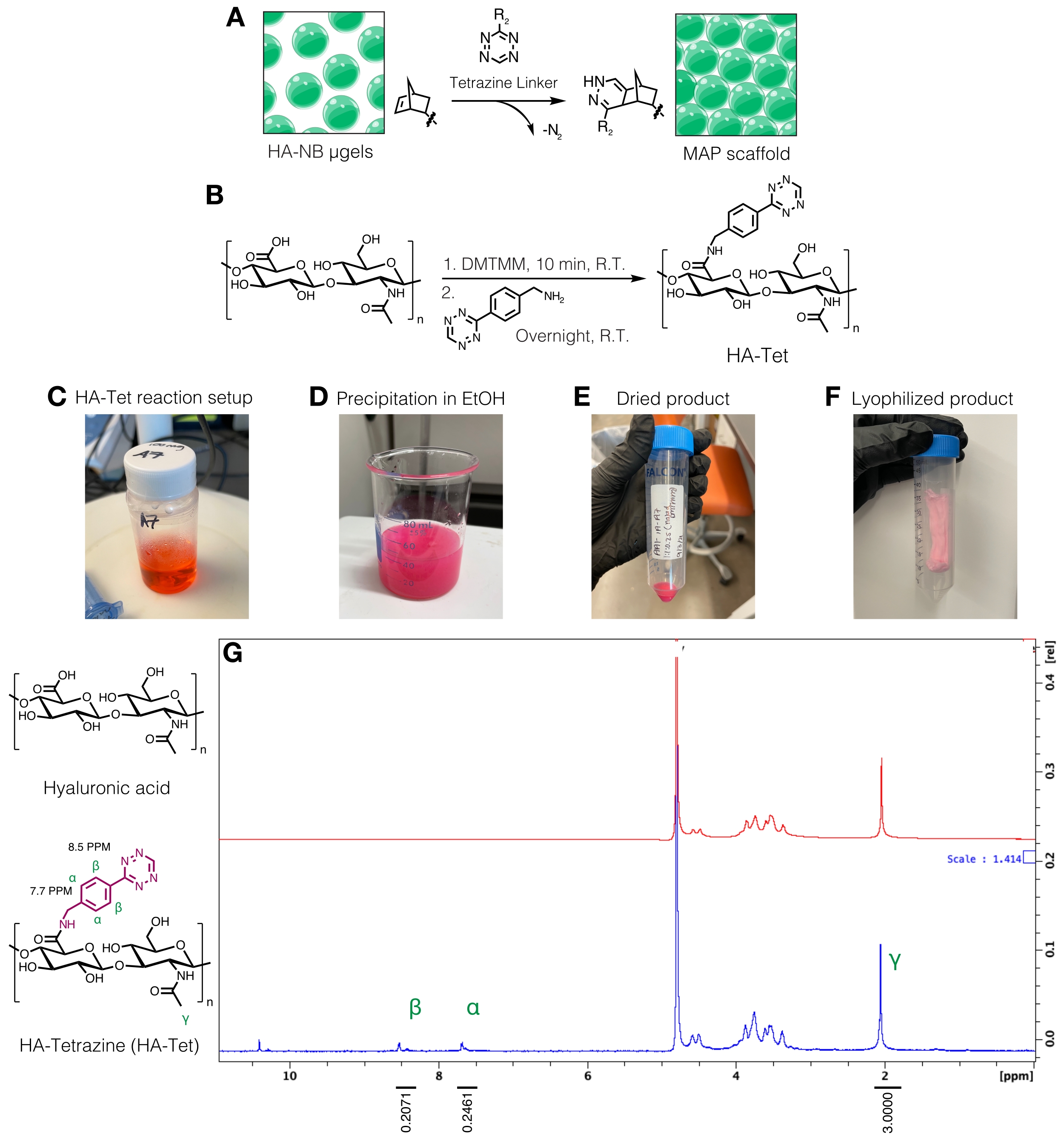
- Tetrazine linker synthesis
NOTE: Tetrazine linkers can be used to interlink µgels bearing free norbornene groups (Figure 3A). HA-tetrazine (HA-Tet) synthesis procedure was adapted from Zhang et al.18 using 79 kDa sodium HA with molar equivalents of 1:1:0.25 of HA-repeat units to DMTMM to tetrazine-amine (Figure 3B)12.- Weigh the reactants. Dissolve the HA at 20 mg/mL in 200 mM MES buffer (pH ~6) by stirring in a beaker or flask on a stir plate. Once dissolved, add the DMTMM to the HA solution and allow to react for approximately 20 min at room temperature. For example, 100 mg HA + 72.8 mg DMTMM + 14.14 mg tetrazine-amine can be used.
- Dissolve the tetrazine-amine at 15 mg/mL in 200 mM MES buffer and add dropwise to the HA/DMTMM solution. Refer to Figure 3C for the HA-Tet reaction setup.
- Add parafilm to the opening of the reaction vessel to minimize evaporation and cover the reaction vessel with foil. Continue stirring while allowing the reaction to proceed for approximately 24 h.
- After 24 h, chill 200 proof ethanol (approximately 10x the reaction volume). On a stir plate, transfer the reaction dropwise to the chilled ethanol to precipitate the HA-Tet (Figure 3D) and continue stirring for 20 min.
- Transfer the solution to 50 mL conical tubes, and then centrifuge at 5,000 x g for 10 min. Pour off the excess ethanol to dispose as waste. Pull vacuum on the HA-Tet in a dessicator to dry overnight. An example of the dried product at this step in the protocol can be found in Figure 3E.
- Purify the HA-Tet using dialysis. Dissolve HA-Tet in 2 M NaCl solution and transfer to cellulose dialysis tubing with a 12-14 kDa molecular weight cut-off. Transfer the filled dialysis tubing to a bucket with 5 L of ultrapure water, and dialyze the HA-Tet against water overnight.
- The next day, remove the water and replace with 1 M NaCl solution for 30 min. Remove the NaCl solution, and then dialyze against ultrapure water for 3 days, replacing the water daily.
- Filter the dialyzed product using 0.2 µm vacuum-driven filter, and then transfer the filtered HA-Tet product to 50 mL conical tubes.
- Flash-freeze the conical tubes in liquid nitrogen for 10 min, and then remove the conical tubes with forceps. Quickly remove the cap and cover with a lab-grade tissue. Secure the tissue with a rubber band and transfer to a lyophilization container or chamber and lyophilize. Store the lyophilized product (Figure 3F) at -20 °C.
- Quantify tetrazine modification by dissolving the HA-Tet at 10 mg/mL in D2O and analyzing via proton NMR (Figure 3G)16.
- To determine the amount of functionalization, first calibrate the D2O solvent peak to 4.8 PPM. Integrate the peak for the HA methyl protons (δ2.05) and calibrate the integration to 3.0. Next, integrate the peaks for the pendant tetrazine groups at δ8.5 (2H) and δ7.7 (2H) (aromatic protons). Normalize the integration of these peaks to the corresponding number of protons to determine the average degree of modification12.
- Interlinking lyo-µgels to form MAP scaffolds for characterization
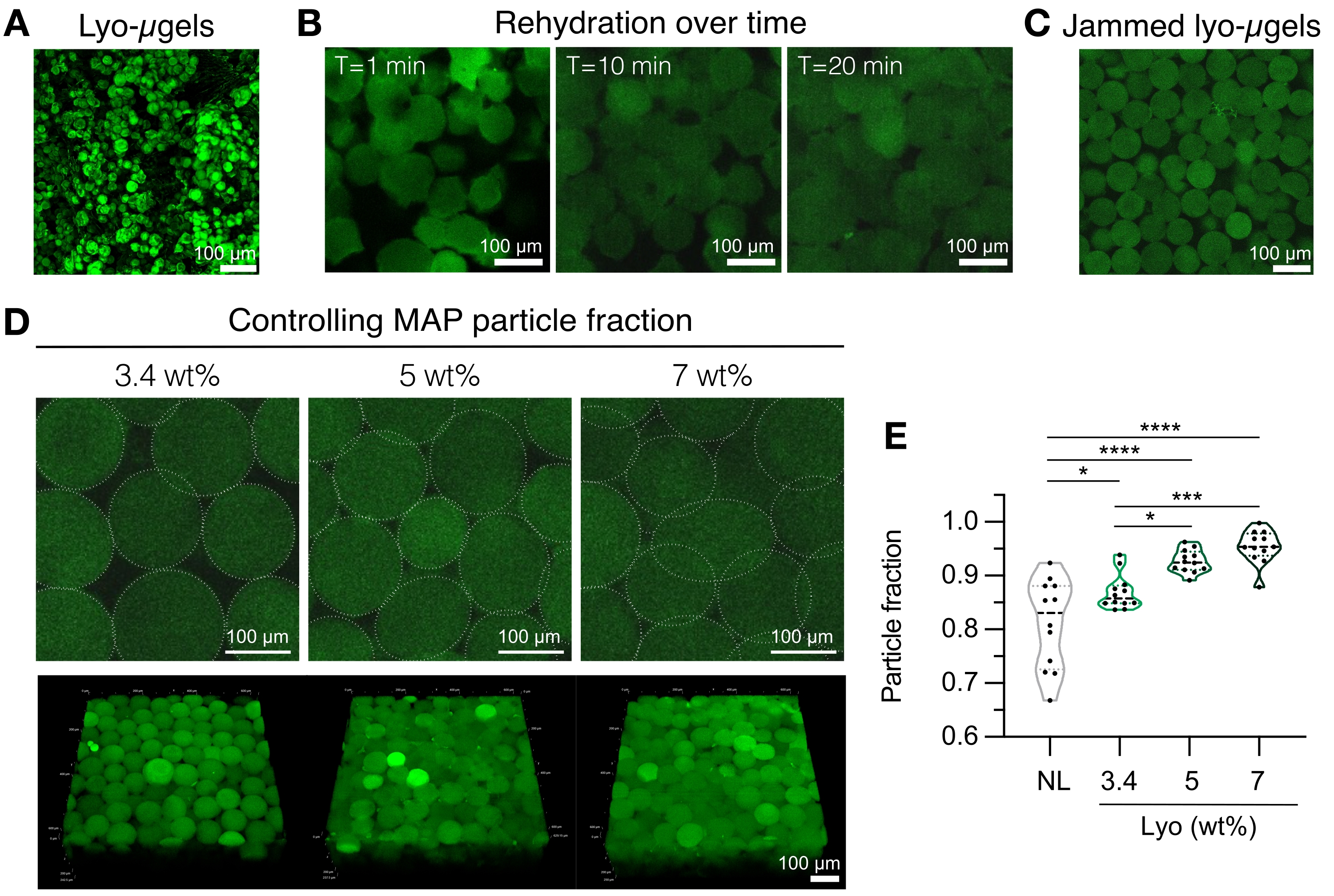
- Prepare the MAP scaffold components (i.e., µgels, HA-Tet, rehydration volume). Weigh the lyo-µgels (Figure 4A) and reconstitute in 84% of the final MAP volume of 1x PBS. Allow the microgels to swell for approximately 20 min (Figure 4B,C). The wt% MAP used for rehydration can be chosen based on the user's preference for final particle fraction (refer to Figure 4D, E).
- Dissolve the HA-Tet in 1x PBS at the chosen concentration (see NOTE below).
NOTE: Changing both the packing fraction (via wt% MAP) as well as the concentration of HA-Tet will alter bulk scaffold mechanical properties. For example, a 3.4 wt% MAP scaffold crosslinked with 0.02 mg/mL HA-Tet (annealing ratio of 2.6 mol Tet:mol HA-NB) generates MAP scaffolds with approximately 700 Pa shear storage modulus12. - Use a displacement pipette to combine the HA-Tet and lyo-µgels and mix well. At this point, the mixture can be transferred via displacement pipette onto glass slides, well plates, or a container of the user's choosing. Allow µgels to anneal at 37 °C for 25 min, and then use a spatula to transfer the MAP scaffolds to well plates filled with 1x PBS. Keep MAP scaffolds in 1x PBS until ready for characterization.
- Calculating MAP scaffold particle fraction
- For improved image quality, transfer MAP scaffold to a glass coverslip using a spatula. Image MAP scaffolds on a confocal microscope using the laser for FITC excitation and emission. Image MAP scaffolds on a 20x objective and obtain a Z-stack traversing 250-300 µm in the Z-direction with a step size of 2.5 µm. Make note of the µm/pixel calibration of the image.
- Import the Z-stack image into the analysis software (see Table of Materials). Select the Add New Surfaces button. Check the box to Segment Only a Region of Interest, and then select the blue arrow button Next: Region of Interest.
- Define a region of interest, keeping track of the X-, Y-, and Z-dimensions of the volume being analyzed. Select the blue arrow button Next: Source Channel.
NOTE: X- and Y-dimensions are in units of pixels while the Z-dimension is the number of steps. A recommended Z-height for the region of interest should include a minimum of two µgels. - Use the Source Channel drop-down list to select the FITC channel. Check the box next to Smooth and input a surface detail of 2.50 µm. Under Thresholding, select Absolute Intensity, and then select the blue arrow button Next: Threshold.
- Use the suggested thresholding value for the FITC channel. Rotate the 3D projection to assess the rendering quality and adjust as needed. Select Next: Classify Surfaces.
NOTE: The Back button can be used to edit previous steps in the process, such as Z-dimension, as needed. - Check whether Number of Voxels is 10.0, and then select the green double arrow button Finish: Execute all creation steps and terminate the wizard.
NOTE: Volume rendering parameters can be stored for batch analysis so that the same settings are applied to analyze all the scaffolds. - To export the data, select the Statistics tab, and then the Detailed tab. Use the second drop-down box to select the variable Volume. Select the floppy disk button Export Statistics on Tab Display to File and save as a spreadsheet file (.xls) when prompted.
- Open the file and use the SUM function on Column A Volume to determine the total volume (µm3) of the µgels in the region of interest.
- Convert the dimensions of the region of interest that was analyzed from pixels to µm. Use the µm/pixel calibration of the image from step 4.3.1 to convert the X- and Y-dimensions. Multiply the Z-dimension (number of steps) by the step size for the image to convert the Z-dimension to µm. Calculate the volume of the region of interest (µm3) by multiplying the X-, Y-, and Z-dimensions.
- To determine the particle fraction of the scaffold, divide the total volume of the µgels in the region of interest (found in step 4.3.8) by the volume of the region of interest (found in step 4.3.9).

Figure 3: Synthesis of tetrazine linker for the fabrication of microporous annealed particle (MAP) scaffolds. (A) Schematic of HA-NB µgels being interlinked with a tetrazine linker to form MAP scaffolds. (B) Reaction scheme for HA-Tet synthesis. (C) The HA-Tet reaction was setup and allowed to react overnight followed by (D) precipitation of HA-Tet in ethanol. (E) Once purified and dried, the HA-Tet was rehydrated and lyophilized to yield (F) a dried, light pink product. (G) Proton NMR analysis shows successful modification of 11% of HA repeat units. Reprinted from Anderson et al.12 with permission from Elsevier. Please click here to view a larger version of this figure.

Figure 4: Rehydration of lyophilized microgels for MAP scaffold fabrication. (A) Maximum intensity projection of dried lyo-µgels (scale bar = 100 µm). (B) After freeze-drying, rehydration of lyo-µgels is shown to take approximately 20 min (scale bar = 100 µm). (C) Lyo-µgels can be rehydrated at varying wt% MAP to produce jammed µgels (scale bar = 100 µm). (D) Increasing the wt% MAP when rehydrating lyo-µgels alters the particle fraction in MAP scaffolds, as shown by single Z-slices of MAP scaffolds and volume projections (scale bar = 100 µm). (E) Using these user-defined wt% MAP scaffolds, unique particle fractions can be achieved (NL = non-lyophilized µgels). A one-way ANOVA with Tukey HSD was performed on the samples (n = 3), with significance reported at p < 0.05 (*), p < 0.01 (**), p < 0.005 (***), and p < 0.001 (****). Reprinted from Anderson et al.12 with permission from Elsevier. Please click here to view a larger version of this figure.
5. 3D cell culture in map scaffolds
- Prepare cell culture devices
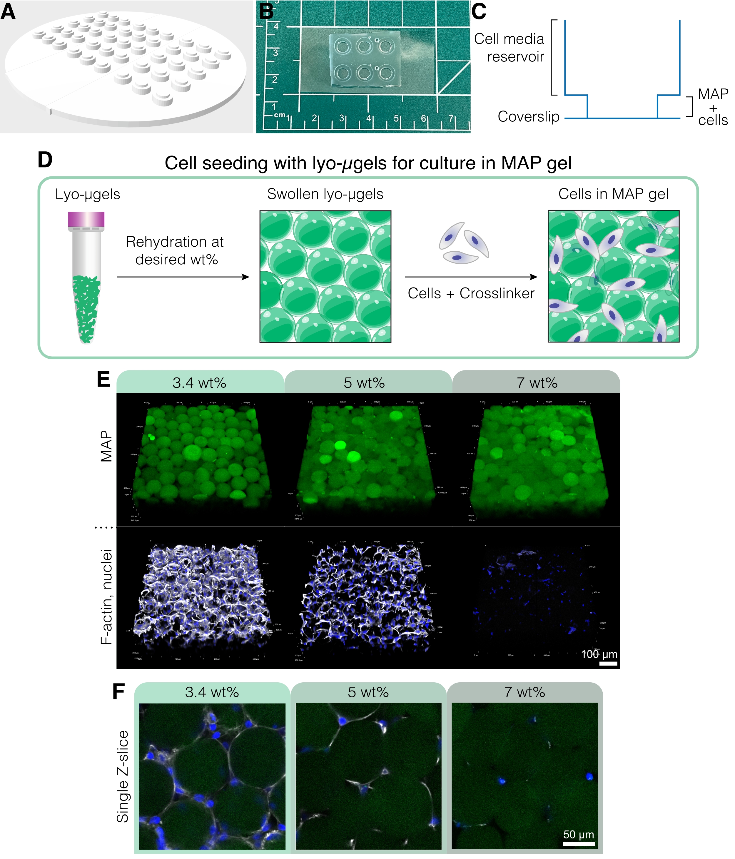
- To create a custom cell culture device for these experiments (Figure 5A-C), use a 3D printer to print a negative mold using the CAD file found in Supplemental Coding File 1.
NOTE: The dimensions of the cell culture device are as follows: 94.9 mm x 94.9 mm x 4.8 mm with 2.6 mm total well height. The diameter of the inner wells and outer wells are 4 mm and 6 mm, respectively. - Mix polydimethylsiloxane (PDMS) elastomer base with the curing agent at a 10:1 ratio by mass. Pour the PDMS mixture into a large plastic Petri dish and degas in a desiccator for approximately 30 min or until all the bubbles have disappeared.
- Once all the bubbles have disappeared, carefully place the 3D printed mold into the PDMS to minimize the formation of new bubbles. Place in the oven at 60 °C for at least 2 h to cure the PDMS.
- Use a knife or razor blade to gently trace around the parameter of the culture device, and then carefully remove the mold. Use a 4 mm biopsy punch to remove any PDMS from the bottom of the wells. Cut the devices to fit on a glass coverslip.
NOTE: Cell culture devices can also be bonded to glass slides, but glass coverslips improve sample imaging. - Use tape to remove dust from the bottom side of the culture devices. Place the clean glass coverslips and culture devices (bottom side up) on a hot plate at 135 °C for at least 15 min to remove moisture.
- In a fume hood, use a corona plasma gun on high on both the glass coverslip and the bottom side of the device for 30 s, and then quickly bond the treated surfaces together. Gently apply pressure to ensure a good seal between the culture device and glass coverslip.
- Repeat step 5.1.6 for all devices, and then place in a 60 °C oven overnight to secure the bond. Autoclave the devices to sterilize before use in vitro.
- To create a custom cell culture device for these experiments (Figure 5A-C), use a 3D printer to print a negative mold using the CAD file found in Supplemental Coding File 1.
- Cell culture in MAP scaffolds
- Prepare the MAP scaffold components (i.e., µgels, HA-Tet, media volume) based on the desired particle fraction (refer to Figure 4D-E). Weigh the lyo-µgels in a sterile hood and reconstitute in 84% of the final MAP volume of cell media based on the chosen wt% MAP. Allow the µgels to swell for approximately 20 min.
NOTE: These methods require the user to weigh the lyo-microgel product for rehydration. For small masses (1 mg or less), it is suggested to first weigh the cryotube before adding and lyophilizing µgels, and then reweigh the tube after lyophilization to determine the mass of the product to minimize error. - Dissolve the HA-Tet in cell media in 16% of the final MAP volume.
NOTE: The following steps for preparing cells for seeding in MAP scaffolds can be altered depending on the cell type being used. In this protocol, D1 mouse mesenchymal cells were grown in Dulbecco's Modified Eagle Medium (DMEM) supplemented with 1% penicillin-streptomycin (pen-strep) and 10% fetal bovine serum (FBS) (see Table of Materials). Standard adherent cell culture protocols should be followed for these cells, with the cultures maintained at 37 °C and 5% CO2 in tissue culture-treated culture vessels. - Once D1 mouse mesenchymal cells have reached 70%-80% confluency, aspirate the media and wash the cells with 1x PBS. Lift the cells by adding enough volume of 1% trypsin-EDTA to cover to surface of the tissue culture vessel. Incubate at 37 °C for 1-3 min, and then quench the trypsinization by adding DMEM media supplemented with 1% pen-strep and 10% FBS at 2x the volume of trypsin-EDTA.
- Centrifuge the cell suspension at 100 x g for 5 min at room temperature to pellet the cells. Aspirate the supernatant media and resuspend the cells in 1 mL DMEM media supplemented with 1% pen-strep and 10% FBS.
- Ensure the cell suspension is well mixed, and then transfer 20 µL to a new microcentrifuge tube. Add 20 µL trypan blue solution and mix well. Use 20 µL of this mixture to count the cells using either a hemocytometer or an automated cell counter with cell counting chamber slides.
- Transfer the number of cells needed for seeding 10,000 cells/µL MAP to a new microcentrifuge tube. Centrifuge at 100 x g for 5 min at room temperature to pellet the cells. Carefully aspirate the supernatant media from the cell pellet without aspirating the cells.
- Add the µgels and crosslinker to the cell pellet with a displacement pipette. Mix well with a displacement pipette, and then seed 10 µL of the mixture per well. When plating, pipette in a circular motion to evenly distribute the mixture in the well.
- Allow the µgels to anneal at 37 °C in the cell incubator for 25 min before adding cell media to fill the wells (~50 µL of media per well). Maintain the 3D cultures at 37 °C and change media as needed. To avoid aspirating the scaffold when changing media, stabilize the pipette tip along the ridge of the upper well.
NOTE: When adding or removing liquid from the culture wells, rest the end of the pipette tip on the ledge above the MAP scaffold to minimize the chance of disrupting or aspirating the scaffold from the well. - At the desired time points, fix samples by removing the media and adding 50 µL of 4% paraformaldehyde per well for 30 min at room temperature. Wash the samples 3x with 50 µL of 1x PBS or preferred buffer. At this point in the protocol, standard methods for immunofluorescence or fluorescence staining can be followed, using 50 µL per well as the working volume.
NOTE: These methods for fixation and cell staining specifically describe the use of fluorescent stains; however, immunostaining with primary and/or secondary antibody conjugations can be performed in these scaffolds as well following the manufacturer's instructions using 50 µL as the working volume per well. - Image cells in MAP scaffolds on a confocal microscope using a 20x objective and obtain a Z-stack traversing 200-250 µm in the Z-direction with a step size of 2.5 µm. An example of fluorescence staining with DAPI (nuclear stain diluted 1:1000 in 0.15% Triton-X in 1x PBS) and phalloidin-647 (F-actin stain diluted 1:40 in 0.15% Triton-X in 1x PBS) is shown in Figure 5E, F with fixed D1 cells cultured in MAP scaffolds for 3 days.
NOTE: Plasma treatment of glass surfaces results in increased hydrophilicity, which has been shown to enhance cell adhesion. Cells will likely be observed spreading along the bottom of the cell culture wells but should not be included in cell counts or cell volume quantification for assessing cell response in MAP scaffolds.
- Prepare the MAP scaffold components (i.e., µgels, HA-Tet, media volume) based on the desired particle fraction (refer to Figure 4D-E). Weigh the lyo-µgels in a sterile hood and reconstitute in 84% of the final MAP volume of cell media based on the chosen wt% MAP. Allow the µgels to swell for approximately 20 min.

Figure 5: Cell culture in MAP scaffolds. (A) The mold for creating cell culture wells can be 3D printed and cast with PDMS. The entire mold is 95 mm in diameter, the large wells are 6 mm in diameter, and the small inner wells are 4 mm in diameter. (B) Once cast with PDMS, the cell culture devices are plasma bonded to coverslips for improved microscopy capabilities. (C) The cross section of a cell culture well depicts the reservoir for cell media (~50 µL) and a smaller reservoir for seeding MAP scaffold with cells (~10 µL). (D) The process of seeding cells in MAP scaffolds first relies on the rehydration of lyo-µgels at the user's desired wt%, followed by mixing with cells and the crosslinker for interlinking the µgels. (E) Cells can be encapsulated in MAP scaffolds (green) with varied wt% MAP. Representative images are from day 5 of D1 cell culture in MAP scaffolds (scale bar = 100 µm). (F) Single Z-slices show differences in cell growth in scaffolds comprising different wt% MAP (scale bar = 50 µm). Reprinted from Anderson et al.12 with permission from Elsevier. Please click here to view a larger version of this figure.
Results
The aim of this protocol is to demonstrate the preparation of microporous annealed particle (MAP) scaffolds with a bio-orthogonal crosslinking scheme as well as controlled particle fractions for 3D cell culture. First, HA was modified with norbornene pendant groups to be used in both microgel formation and interlinking to form MAP scaffolds. Using these methods, approximately 31% of HA repeat units were successfully modified with a norbornene functional handle (Figure 1A). Microfluidic devic...
Discussion
Microfluidic production of HA-NB microgels has been shown to generate microgels with a narrower range of size distribution than emulsion batch production3,9. The microgels described in this protocol were formulated using an MMP-cleavable crosslinker (Ac-GCRDGPQGIWGQDRCG-NH2) to support material degradation. However, HA-NB microgels can also be crosslinked using an alternative di-thiol linker such as dithiothreitol (DTT), which is non-degradable. S...
Disclosures
ARA and TS have filed a provisional patent on this technology.
Acknowledgements
The authors would like to thank the National Institutes of Health, the National Institutes of Neurological Disorders and Stroke (1R01NS112940, 1R01NS079691, R01NS094599), and the National Institute of Allergy and Infectious Disease (1R01AI152568). This work was performed in part at the Duke University Shared Materials Instrumentation Facility (SMIF), a member of the North Carolina Research Triangle Nanotechnology Network (RTNN), which is supported by the National Science Foundation (award number ECCS-2025064) as part of the National Nanotechnology Coordinated Infrastructure (NNCI). The authors would like to thank the lab's former post-doc Dr. Lucas Schirmer as well as Ethan Nicklow for their assistance in generating the 3D printed device for cell culture experiments.
Materials
| Name | Company | Catalog Number | Comments |
| 1 mL Luer-Lok syringe sterile, single use, polycarbonate | BD | 309628 | |
| 5 mL Luer-Lok syringe sterile, single use, polycarbonate | BD | 309646 | |
| Alexa Fluor 488 C5 maleimide | Invitrogen | A10254 | For synthesis of fluorescently-labeled tetrazine |
| Alexa Fluor 647 Phalloidin | Invitrogen | A22287 | For staining cell culture samples |
| Aluminum foil | VWR | 89107-726 | |
| Biopsy punch with plunger, 1.0 mm | Integra Miltex | 69031-01 | |
| Biopsy punch, 4 mm | Integra Miltex | 33-34 | |
| Blunt needle, 23 G 0.5", Non-Sterile, Capped | SAI Infusion Technologies | B23-50 | |
| Bottle-top vacuum filter, 0.22 μm | Corning | CLS430521 | |
| Calcium chloride | VWR | 1B1110 | For microgel washing buffer |
| Capillary-piston assemblies for positive-displacement pipettes, 1000 μL max. volume | Rainin | 17008609 | |
| Capillary-piston assemblies for positive-displacement pipettes, 25 μL max. volume | Rainin | 17008605 | |
| Capillary-piston assemblies for positive-displacement pipettes, 250 μL max. volume | Rainin | 17008608 | |
| Countess Cell Counting Chamber Slides | Invitrogen | C10228 | |
| Countess II FL Automated Cell Counter | Invitrogen | AMQAF1000 | |
| Centrifuge tube, 15 mL | CELLTREAT | 667015B | |
| Centrifuge tube, 50 mL | CELLTREAT | 229421 | |
| Chloroform, ACS grade, Glass Bottle | Stellar Scientific | CP-C7304 | For synthesis of fluorescently-labeled tetrazine |
| Corona plasma gun, BD-10A High Frequency Generator | ETP | 11011 | |
| CryoTube Vials, Polypropylene, Internal Thread with Screw Cap | Nunc | 368632 | |
| D1 mouse mesenchymal cells | ATCC | CRL-12424 | Example cell line for culture in MAP gels |
| DAPI | Sigma-Aldrich | D9542 | For staining cell culture samples |
| Deuterium oxide, 99.9 atom% D | Sigma-Aldrich | 151882 | For NMR spectroscopy |
| Dialysis tubing, regenerated cellulose membrane, 12-14 kDa molecular weight cut-off | Spectra/Por | 132703 | For purifying HA-NB and HA-Tet |
| Diethyl ether | VWR | BDH1121-4LPC | For synthesis of fluorescently-labeled tetrazine |
| Dimethylformamide | Sigma-Aldrich | 277056 | For synthesis of fluorescently-labeled tetrazine |
| 4-(4,6-dimethoxy-1,3,5-triazin-2-yl)-4-methylmorpholinium chloride (DMTMM) | TCI-Chemicals | D2919 | For modifying HA |
| Dithiothreitol (DTT) | Thermo Scientific | R0861 | Non-degradable dithiol linker (substitute for MMP-cleavable peptide) |
| Dulbecco's Modified Eagle's Medium (DMEM), high glucose, w/ 4500 mg/L glucose, L-glutamine, sodium pyruvate, and sodium bicarbonate, liquid, sterile-filtered, suitable for cell culture | Sigma-Aldrich | D6429-500ML | For D1 cell culture |
| EMS Paraformaldehyde, Granular | VWR | 100504-162 | For making 4% PFA |
| Ethanol absolute (200 proof) | KOPTEC | 89234-850 | |
| Fetal bovine serum (FBS) | ATCC | 30-2020 | For D1 cell culture |
| Heating Plate | Kopf Instruments | HP-4M | |
| Hemacytometer with coverglass | Daigger Scientific | EF16034F | |
| 2-[4-(2-hydroxyethyl)piperazin-1-yl]ethanesulfonic acid (HEPES) | Sigma-Aldrich | H3375 | |
| Sodium hyaluronate, 79 kDa average molecular weight, produced in bacteria Streptococcus zooepidemicus, pharmaceutical grade, microbial contamination <100 CFU/g, bacterial endotoxins <0.050 IU/mg | Contipro | N/A | 79 kDa average molecular weight was used for HA-Tet synthesis, but these methods could be adapted for other molecular weights. |
| IMARIS Essentials software package | Oxford Instruments | N/A | Microscopy image analysis software |
| Infusion pump, dual syringe | Chemyx | N/A | |
| Kimwipe | Kimberly-Clark | 34120 | |
| Laboratory stand with support lab clamp | Geyer | 212100 | |
| Liquid nitrogen | Airgas | NI 180LT22 | |
| Lithium Phenyl(2,4,6-trimethylbenzoyl)phosphinate | TCI-Chemicals | L0290 | |
| Lyophilizer | Labconco | N/A | Labconco FreeZone 6 plus has been discontinued, but other lab grade console freeze dryers could be used for this protocol. |
| Methyltetrazine-PEG4-maleimide | Kerafast | FCC210 | For synthesis of fluorescently-labeled tetrazine |
| 2-(4-Morpholino)ethane Sulfonic Acid (MES) | Fisher Scientific | BP300-100 | For modifying HA |
| Micro cover glass, 24 x 60 mm No. 1 | VWR | 48393-106 | |
| Microfluidic device SU8 master wafer | FlowJem | Custom design made either in-house in clean room or outsourced | |
| Mineral oil, heavy | Sigma-Aldrich | 330760 | |
| MMP-cleavable dithiol crosslinker peptide (Ac-GCRDGPQGIWGQDRCG-NH2) | GenScript | N/A | |
| 5-Norbornene-2-methylamine | TCI-Chemicals | 95-10-3 | For HA-NB synthesis |
| Packing tape | Scotch | 3M 1426 | |
| Parafilm | Bemis | PM996 | |
| PEG(thiol)2 | JenKem Technology USA | A4001-1 | For synthesis of fluorescently-labeled tetrazine |
| Penicillin-Streptomycin, 10,000 units/mL | Thermo Fisher Scientific | 15140122 | For D1 cell culture |
| Petri dish, polystyrene, disposable, Dia. x H=150 x 15 mm | Corning | 351058 | |
| Pluronic F-127 | Sigma-Aldrich | P2443 | For washing HMPs |
| Phosphate buffered saline (PBS) 1x | Gibco | 10010023 | |
| RainX water repellent glass treatment | Grainger | 465D20 | Synthetic hydrophobic treatment solution for microfluidic device treatment |
| RGD peptide (Ac-RGDSPGERCG-NH2) | GenScript | N/A | |
| Rubber bands | Staples | 112417 | |
| Sodium chloride | Chem-Impex | 30070 | For dialysis |
| Span 80 for synthesis | Sigma-Aldrich | 1338-43-8 | |
| Sylgard 184 Silicone Elastomer | Electron Microscopy Science | 4019862 | polydimethylsiloxane (PDMS) elastomer for making microfluidic devices and tissue culture devices |
| Syringe filter, Whatman Uniflo, 0.2 μm PES, 13 mm diameter | Cytvia | 09-928-066 | |
| Tetraview LCD digital microscope | Celestron | 44347 | |
| Tetrazine-amine HCl salt | Chem-Impex | 35098 | For HA-Tet synthesis |
| Triethylamine | Sigma-Aldrich | 471283 | For synthesis of fluorescently-labeled tetrazine |
| Tris(2-carboxyethyl)phosphine (TCEP) | Millipore Sigma | 51805-45-9 | |
| Triton X-100 | VWR | 97063-864 | |
| Trypan blue solution, 0.4% | Thermo Fisher Scientific | 15250061 | |
| Trypsin EDTA (0.25%), Phenol red | Fisher Scientific | 25-200-056 | For lifting adherent cells to seed in MAP gels |
| Tygon ND-100-80 Non-DEHP Medical Tubing, Needle Gauge=23, Wall Thickness=0.020 in, Internal diameter = 0.020, Outer diameter = 0.060 in | Thomas Scientific | 1204G82 | |
| UV curing system controller, LX500 LED | OmniCure | 010-00369R | |
| UV curing head, LED spot UV | OmniCure | N/A | |
| UV light meter, Traceable | VWR | 61161-386 | |
| Vacuum dessicator | Bel-Art | 08-594-15C | |
| X-Acto Z Series Precision Utility Knife | Elmer's | XZ3601W |
References
- Griffin, D. R., Weaver, W. M., Scumpia, P. O., Di Carlo, D., Segura, T. Accelerated wound healing by injectable microporous gel scaffolds assembled from annealed building blocks. Nature Materials. 14 (7), 737-744 (2015).
- Daly, A. C., Riley, L., Segura, T., Burdick, J. A. Hydrogel microparticles for biomedical applications. Nature Reviews Materials. 5 (1), 20-43 (2020).
- Darling, N. J., et al. Click by click Microporous Annealed Particle (MAP) scaffolds. Advanced Healthcare Materials. 9 (10), 1901391 (2020).
- Truong, N. F., et al. Microporous annealed particle hydrogel stiffness, void space size, and adhesion properties impact cell proliferation, cell spreading, and gene transfer. Acta Biomaterialia. 94, 160-172 (2020).
- Pfaff, B. N., et al. Selective and improved photoannealing of Microporous Annealed Particle (MAP) scaffolds. ACS Biomaterials Science & Engineering. 7 (2), 422-427 (2021).
- Sideris, E., et al. Particle hydrogels based on hyaluronic acid building blocks. ACS Biomaterials Science & Engineering. 2 (11), 2034-2041 (2016).
- Caldwell, A. S., Campbell, G. T., Shekiro, K. M. T., Anseth, K. S. Clickable microgel scaffolds as platforms for 3D cell encapsulation. Advanced Healthcare Materials. 6 (15), 1700254 (2017).
- Qazi, T. H., et al. Anisotropic rod-shaped particles influence injectable granular hydrogel properties and cell invasion. Advanced Materials. 34 (12), 2109194 (2022).
- Wilson, K. L., et al. Stoichiometric post modification of hydrogel microparticles dictates neural stem cell fate in microporous annealed particle scaffolds. Advanced Materials. 34 (33), 2201921 (2022).
- Muir, V. G., Qazi, T. H., Shan, J., Groll, J., Burdick, J. A. Influence of microgel fabrication technique on granular hydrogel properties. ACS Biomaterials Science & Engineering. 7 (9), 4269-4281 (2021).
- Highley, C. B., Song, K. H., Daly, A. C., Burdick, J. A. Jammed microgel inks for 3D printing applications. Advanced Science. 6 (1), 1801076 (2018).
- Anderson, A. R., Nicklow, E., Segura, T. Particle fraction as a bioactive cue in granular scaffolds. Acta Biomaterialia. 150, 111-127 (2022).
- Pruett, L., Ellis, R., McDermott, M., Roosa, C., Griffin, D. R. Spatially heterogeneous epidermal growth factor release from microporous annealed particle (MAP) hydrogel for improved wound closure. Journal of Materials Chemistry B. 9 (35), 7132-7139 (2021).
- Sheikhi, A., et al. Microengineered emulsion-to-powder technology for the high-fidelity preservation of molecular, colloidal, and bulk properties of hydrogel suspensions. ACS Applied Polymer Materials. 1 (8), 1935-1941 (2019).
- Brower, K., White, A. K., Fordyce, P. M. Multi-step variable height photolithography for valved multilayer microfluidic devices. Journal of Visualized Experiments. (119), e55276 (2017).
- JoVE. Nuclear Magnetic Resonance (NMR) Spectroscopy. JoVE Science Education Database. Organic Chemistry. JoVE. , (2022).
- Roosa, C., et al. Microfluidic synthesis of microgel building blocks for microporous annealed particle scaffold. Journal of Visualized Experiments. (184), e64119 (2022).
- Zhang, H., Dicker, K. T., Xu, X., Jia, X., Fox, J. M. Interfacial bioorthogonal crosslinking. ACS Macro Letters. 3 (8), 727-731 (2014).
- Welzel, P. B., et al. Cryogel micromechanics unraveled by atomic force microscopy-based nanoindentation. Advanced Healthcare Materials. 3 (11), 1849-1853 (2014).
- Plieva, F., Huiting, X., Galaev, I. Y., Bergenståhl, B., Mattiasson, B. Macroporous elastic polyacrylamide gels prepared at subzero temperatures: control of porous structure. Journal of Materials Chemistry. 16 (41), 4065-4073 (2006).
- Rommel, D., et al. Functionalized microgel rods interlinked into soft macroporous structures for 3D cell culture. Advanced Science. 9 (10), 2103554 (2022).
- Kurt, E., Segura, T. Nucleic acid delivery from granular hydrogels. Advanced Healthcare Materials. 11 (3), 2101867 (2021).
- Isaac, A., et al. Microporous bio-orthogonally annealed particle hydrogels for tissue engineering and regenerative medicine. ACS Biomaterials Science & Engineering. 5 (12), 6395-6404 (2019).
- Truong, N. F., Lesher-Pérez, S. C., Kurt, E., Segura, T. Pathways governing polyethylenimine polyplex transfection in Microporous Annealed Particle scaffolds. Bioconjugate Chemistry. 30 (2), 476-486 (2019).
- Koh, J., et al. Enhanced in vivo delivery of stem cells using microporous annealed particle scaffolds. Small. 15 (39), 1903147 (2019).
- Li, F., et al. Cartilage tissue formation through assembly of microgels containing mesenchymal stem cells. Acta Biomaterialia. 77, 48-62 (2018).
Reprints and Permissions
Request permission to reuse the text or figures of this JoVE article
Request PermissionThis article has been published
Video Coming Soon
Copyright © 2025 MyJoVE Corporation. All rights reserved