A subscription to JoVE is required to view this content. Sign in or start your free trial.
An Ex Vivo Porcine Model for Hydrodynamic Testing of Experimental Aortic Valve Procedures and Novel Medical Devices
In This Article
Summary
We present a method for mounting a porcine aortic valve on a pulse duplicator to test its hydrodynamic properties. This method can be used to determine the change in hydrodynamics after the application of an experimental procedure or novel medical device prior to use in a large animal model.
Abstract
The options for testing new cardiac procedures and investigative medical devices prior to use in an animal model are limited. In this study, we present a method for mounting a porcine aortic valve in a pulse duplicator to evaluate its hydrodynamic properties. These properties can then be evaluated before and after the procedure under investigation is performed and/or the investigative medical device is applied. Securing the inflow segment presents some difficulty owing to the lack of circumferential myocardium in the left ventricular outflow tract. This method addresses that issue by securing the inflow segment using the anterior leaflet of the mitral valve and then suturing the left ventricular free wall around the inflow fixture. The outflow segment is secured simply by inserting the fixture into an incision in the superior aspect of the aortic arch. We found that specimens had significantly different hydrodynamic properties before and after tissue fixation. This finding induced us to use fresh specimens in our testing and should be considered when using this method. In our work, we used this method to test novel intracardiac patch materials for use in the valvular position by performing an aortic valve neocuspidization procedure (Ozaki procedure) on the mounted porcine aortic valves. These valves were tested before and after the procedure to assess the change in hydrodynamic properties in comparison to the native valve. Herein, we report a platform for hydrodynamic testing of experimental aortic valve procedures that enables comparison with the native valve and between different devices and techniques used for the procedure under investigation.
Introduction
Aortic valve disease represents a significant public health burden, particularly aortic stenosis, which affects 9 million people worldwide1. Strategies to address this disease are currently evolving and include aortic valve repair and aortic valve replacement. In the pediatric population especially, there is a significant incentive to repair rather than replace the valve since currently available prostheses are prone to structural valve degeneration (SVD) and are not growth tolerant, requiring reoperation for re-replacement as the patient grows. Even the Ross procedure, which replaces the diseased aortic valve (AV) with the native pulmonary valve (PV), requires a prosthesis or graft in the pulmonary position that is also subject to SVD and often limited growth tolerance2. New approaches to aortic valve disease are being developed, and there is a need for testing in a biologically relevant context prior to application in a large animal model.
We have developed a method for testing a porcine AV that can provide insights into the function of the valve before and after an investigational procedure or application of a novel medical device. By mounting the porcine AV on a commercially available pulse duplicator machine, we are able to compare the hydrodynamic characteristics that are commonly used in the investigation and ultimately approval of valve prostheses, including regurgitation fraction (RF), effective orifice area (EOA), and mean positive pressure difference (PPD)3,4. The intervention can then be fine-tuned in a biologically relevant context before use in a large animal model, thus limiting the number of animals needed to produce a procedure or prosthesis that can be used in humans. The hearts used for this experiment can be obtained from the local abattoir or waste tissue from other experiments, so it is not necessary to sacrifice an animal solely for the purposes of this experiment.
In our work, we used this method to develop a novel patch material for valve repair and replacement. We tested the hydrodynamic function of a variety of patch materials by performing an aortic valve neocuspidization procedure (Ozaki procedure5,6,7) on porcine AVs and testing them in the pulse duplicator before and after the procedure. This enabled us to fine-tune the material based on its hydrodynamic performance. Thus, this method provides a platform for hydrodynamic testing of experimental procedures and novel medical devices for use on the AV prior to application in a large animal model.
Protocol
All research was performed in compliance with institutional guidelines for the care of animals.
1. Considerations and preparations for the experiment
- Utilize a suitable pulse duplicator (PD) for the simulation of cardiac output through the AV. The PD will need to be able to accommodate biological materials and be able to be cleaned.
- Utilize PD settings appropriate for testing the AV: 70 mL displacement volume and 70 beats per minute (5 L/min cardiac output), 35% of the cardiac cycle in systole, 100 mmHg mean transvalvular pressure gradient, 120 maximum pressure gradient, and 80 minimum pressure gradient.
- Use room temperature (RT) normal saline (0.9% NaCl) as the fluid medium.
- Locate or create (using 3D printing or a similar method) suitable fixtures for mounting the porcine AV for testing on the PD.
- Utilize fixtures that are modeled on the fixtures provided with the pulse duplicator with the following specifications: ensure that the inner diameter of the fixture is similar to the diameter of the AV being studied, the attachment length is at least 2 cm, and the usable attachment width is at least 4 cm (Figure 1).
- Use rubber O-rings as gaskets on the ends of the fixtures.
- Obtain a heart specimen after cardiectomy (Figure 2A).
- Use porcine cardiac specimens from the slaughterhouse or waste tissue from animals that are otherwise healthy and have not been part of any experimental protocols that will affect their hearts.
- Obtain specimen after cardiectomy or perform post-mortem cardiectomy, including transection of the superior vena cava, inferior vena cava, main pulmonary artery (PA), all pulmonary veins, and aorta at the distal aspect of the aortic arch.
NOTE: Fresh specimens, less than 6 h post-mortem or stored in sterile saline with a 1% antibiotic solution (penicillin and streptomycin) in a 4 oC refrigerator for up to 7 days, should be used for this experiment. Tissues fixed in formalin or glutaraldehyde will produce altered hydrodynamic results due to increased stiffness.

Figure 1: Custom 3D printed fixtures for mounting the porcine aortic valves on the pulse duplicator. As noted in the protocol, the attachment length should be at least 2 cm, and the usable attachment width should be at least 4 cm. Please click here to view a larger version of this figure.
2. Resection of right-sided structures
- Dissect the PA off the aorta with Metzenbaum scissors until ventricular tissue is visible (Figure 2B).
- Dissect and ligate with silk ties both coronary arteries at their origin from the aortic sinuses, taking care not to narrow the sinuses.
- Transect the coronary arteries distal to the silk ties.
- Incise the right ventricle (RV) between the aorta and the PA at the base of the pulmonary valve using Metzenbaum scissors (Figure 2C).
- Beginning anteriorly, continue the incision circumferentially along the interventricular septum to remove the RV free wall (Figure 2D, E).
- Continue the incision posteriorly through the tricuspid valve annulus along the interatrial septum to remove all right atrial tissue (Figure 2F).

Figure 2: Cardiectomy specimen and resection of right-sided structures. (A) Cardiectomy specimen. (B) Main pulmonary artery dissected off the aorta until ventricular tissue is visible. (C) Incising the right ventricle (RV) at the base of the pulmonary valve. (D) Continuing the incision along the interventricular septum anteriorly. (E) Removing the RV-free wall by continuing the incision circumferentially along the interventricular septum. (F) Specimen with right-sided structures removed. Please click here to view a larger version of this figure.
3. Preparation of the left ventricular outflow tract (LVOT) for cannulation with the PD fixture
- Incise the left atrium (LA) through the right pulmonary vein ostium parallel to the aorta using Metzenbaum scissors (Figure 3A).
NOTE: Although limited variability exists, porcine pulmonary vein anatomy generally terminates in two pulmonary vein ostia entering the LA8. - Continue the incision towards the anterolateral commissure of the mitral valve (MV), leaving at least a 3 mm cuff of atrial tissue on the aorta side.
- Trim excess LA tissue, maintaining the 3 mm cuff of atrial tissue on the aorta and the MV annulus circumferentially (Figure 3B).
- Extend the incision onto the left ventricle (LV) through the anterolateral commissure of the MV, taking care to preserve the anterolateral papillary muscle (Figure 3C).
- Divide chordae tendineae from the anterolateral papillary muscle to the posterior MV leaflet, preserving attachments to the anterior MV leaflet.
- Continue the incision to the apex of the heart.
- Trim excess LV tissue below the papillary muscles, preserving both papillary muscles (Figure 3D).

Figure 3: Preparation of the left ventricular outflow tract for cannulation with the pulse duplicator fixture. (A) Incising the left atrium (LA) through the ostium of the right pulmonary vein. (B) Excess LA tissue trimmed, maintaining at least a 3 mm cuff of atrial tissue on the aorta and maintaining the mitral valve annulus circumferentially. (C) Extending the incision onto the left ventricle (LV) through the anterolateral commissure of the mitral valve. (D) Removing excess LV tissue below the papillary muscles. Scissors are visible in the upper right corner of the image. Please click here to view a larger version of this figure.
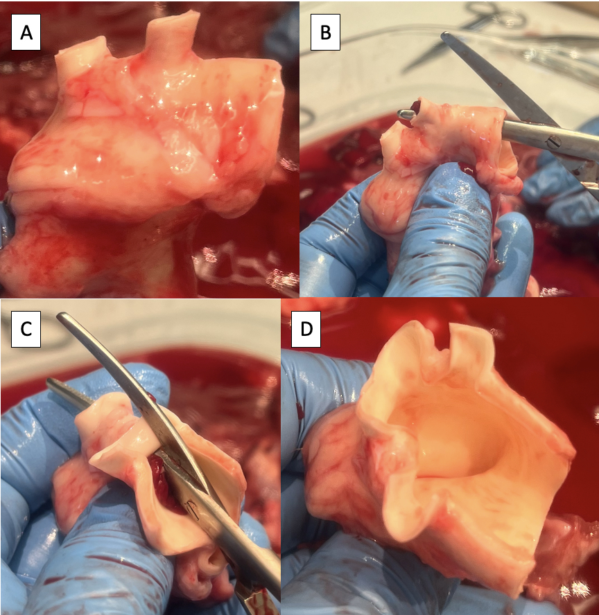
4. Preparation of the aorta for cannulation with the PD fixture
- Trim any excess lymphatic, connective, or pulmonary artery tissue off the aorta (Figure 4A).
- Incise the superior aspect of the aortic arch from the descending aorta to the left subclavian artery using Metzenbaum scissors (Figure 4B).
- Continue the incision on the superior aspect of the aortic arch from the left subclavian artery to the brachiocephalic trunk (Figure 4C, D).
NOTE: Branches of the porcine aortic arch from distal to proximal include the left subclavian artery and the brachiocephalic trunk, which gives rise to the right subclavian artery, right carotid artery, and left carotid artery9.

Figure 4: Preparation of the aorta for cannulation with the pulse duplicator fixture. (A) Aortic arch with excess tissue removed. Note the two arch vessels in the porcine aortic arch, the brachiocephalic trunk, and the left subclavian artery. (B) Starting the incision along the superior aspect of the aortic arch from the descending aorta to the left subclavian artery. (C) Continuing the incision along the superior aspect of the aortic arch from the left subclavian artery to the brachiocephalic trunk. (D) Completed aortic arch incision. Please click here to view a larger version of this figure.
5. Cannulation of the LVOT with the PD fixture
- Test the positioning of the fixture in the LVOT and trim excess LV tissue.
- Insert the fixture into the LVOT under the anterior leaflet of the MV.
- Wrap the LV-free wall around the fixture.
- Trim excess LV tissue to maintain a tight wrap around the fixture.
- Remove half of the thickness of the LV free wall starting at the interventricular septum, maintaining at least 1 cm of epicardium at the free edge to maintain the integrity of the suture line (Figure 5A).
- Trim 1 cm of tissue off the superior corner of the LV free wall wrap (Figure 5A).
- Position the fixture in the LVOT with the supporting rod attachment hole 1 cm behind the LV incision (Figure 5B).
- Take care not to insert the fixture too far into the LVOT such that it dilates the AV annulus.
- Fasten the anterior leaflet of the MV to the fixture using one or two 6-inch zip ties positioned between the chordae tendineae of the leaflet (Figure 5C).
- Suture the LV free wall around the fixture (Figure 5D).
- Start by suturing the cuff of LA tissue on the aorta to the MV annulus using a simple running suture with a taper point needle.
- Continue the running stitch onto the LV, not tearing the LV tissue.

Figure 5: Cannulation of the left ventricular outflow tract with the pulse duplicator fixture. (A) One-half thickness of the LV free wall removed with 1 cm of epicardium maintained at the free edge. The dotted line indicates the 1 cm area to be removed from the superior corner of the LV free wall wrap. (B) Supporting rod attachment hole positioned 1 cm behind the LV free wall incision. (C) Zip tie fastening the anterior leaflet of the MV to the proximal fixture. (D) LV free wall sutured around the fixture. Please click here to view a larger version of this figure.
6. Cannulation of the aorta with PD fixture and final preparation for PD testing
- Measure the diameter of the AV using Hegar dilators to assist with the interpretation of the results of PD testing.
- Identify the neutral position of the aorta by lifting the specimen off the table by grasping the aorta (Figure 6A).
- Insert the PD fixture into the aorta, taking care to line up the rod attachment holes in the neutral position of the aorta.
- Check the length of the specimen by inserting the support rods.
- Secure the PD fixture to the aorta using one or two 6-inch zip ties (Figure 6B).
- Secure the LVOT around the PD fixture using one or two 8-inch zip ties.
- Secure the support rods in place using screws provided with the PD set.
- Place the specimen in PD and start the test (Figure 6C, Video 1, and Video 2).
- Suture any leaks as needed.

Figure 6: Cannulation of the aorta and testing in the pulse duplicator. (A) Lifting the specimen off the table by the aorta to identify the neutral position of the aorta. (B) Distal fixture secured in the aorta with zip ties. (C) Specimen mounted in the pulse duplicator for hydrodynamic testing. Please click here to view a larger version of this figure.
7. Perform experimental procedure
NOTE: Perform experimental procedures like, the Ozaki procedure as previously described5,6,7, and repeat PD testing.
- If the tissue has become desiccated during the procedure, tighten the zip ties and reinforce the suture line as needed.
8. Long-term storage of specimen (if desired)
- Place specimen in formalin 10% for 168 h (1 week)10,11.
- After tissue fixation, wash the specimen with deionized water and place it in ethanol 70% for long-term storage.
Results
The representative data collected from the pulse duplicator includes regurgitation fraction (RF), effective orifice area (EOA), and mean positive pressure difference (PPD). The RF and EOA, in particular, are used in the ISO standards for prosthetic valves (ISO 5840) and will be important to collect if prosthetic valve products are under investigation. The PPD offers information regarding how much pressure is required to open the valve and is commonly referenced when discussing prosthetic valve replacement
Discussion
The method presented here provides a platform for hydrodynamic testing of the AV in order to examine the effect of an experimental procedure or a novel medical device. By mounting the native aortic valve on a pulse duplicator machine, we are able to determine the effect of the experimental procedure on all the hydrodynamic parameters used in the investigation and approval of novel valve prostheses (ISO 5840). This provides an opportunity to fine-tune procedures and prostheses prior to use in a large animal model.
Disclosures
The authors have no relevant financial conflicts of interest to disclose.
Acknowledgements
We would like to thank the lab of Dr. Gordana Vunjak-Novakovic, including Julie Van Hassel, Mohamed Diane, and Panpan Chen, for allowing us to use cardiac waste tissue from their experiments. This work was supported by the Congenital Heart Defect Coalition in Butler, NJ, and the National Institutes of Health in Bethesda, MD (5T32HL007854-27).
Materials
| Name | Company | Catalog Number | Comments |
| 3D Printer | Ultimaker | Ultimaker S5 | Used for printing custom fixtures for hydrodynamic testing |
| Crile-Wood Needle Driver | Emerald Instruments | 2.0638.15 | Used for suturing ventricle |
| Debakey Forceps | Jarit | 320-110 | Used for dissection and sample preparation (can use multiple if working with an assistant) |
| Ethanol 200 proof | Decon Labs Inc. | DSP-MD.43 | Used for fixed tissue storage |
| Formalin 10% | Epredia | 5701 | Used for tissue fixation |
| Gerald Forceps | Jarit | 285-126 | Used for dissection and sample preparation |
| Glass jars | QAPPDA | B07QCP54Z3 | Used for tissue storage |
| Glutaraldehyde 25% | Electron Microscopy Sciences | 16400 | Used for tissue fixation |
| HEPES 1 M buffer solution | Fisher | BP299-100 | Used to make glutaraldehyde 0.6% |
| Mayo Scissors | Jarit | 099-200 | Used for cutting suture |
| Metzenbaum Scissors | Jarit | 099-262 | Used for dissection and sample preparation |
| O-ring | Sterling Seal & Supply Inc. | AS568-117 | Used as a gasket on the end of the 3D printed fixtures |
| Polylactic acid resin | Ultimaker | 1609 | Used for 3D printing fixtures |
| Polyproplene suture | Covidien | VP-762-X | Used for suturing ventricle, tapered needle |
| Pulse Duplicator | BDC Laboratories | HDTi-6000 | Used for hydrodynamic testing |
| Silk ties | Covidien | S-193 | Used for ligating coronary arteries |
| Tonsil Clamp | Aesculap | BH957R | Used for coronary artery dissection |
| Zip ties (6 inch) | Advanced Cable Ties, Inc. | AL-06-18-9-C | Used for securing sample to fixtures, 157.14 mm long (6 inches), 2.5 mm wide |
| Zip ties (8 inch) | GTSE | GTSE-20025B.1000 | Used for securing sample to fixtures, 203 mm long (8 inches), 2.5 mm wide |
References
- Aluru, J. S., Barsouk, A., Saginala, K., Rawla, P., Barsouk, A. Valvular heart disease epidemiology. Medical Science. 10 (2), 32 (2022).
- Herrmann, J. L., Brown, J. W. Seven decades of valved right ventricular outflow tract reconstruction: The most common heart procedure in children. The Journal of Thoracic and Cardiovascular Surgery. 160 (5), 1284-1288 (2020).
- Rotman, O. M., Bianchi, M., Ghosh, R. P., Kovarovic, B., Bluestein, D. Principles of TAVR valve design, modelling, and testing. Expert Review of Medical Devices. 15 (11), 771-791 (2018).
- Pibarot, P., et al. Imaging for predicting and assessing prosthesis-patient mismatch after aortic valve replacement. JACC Cardiovascular Imaging. 12 (1), 149-162 (2019).
- Ozaki, S., et al. Aortic valve reconstruction using self-developed aortic valve plasty system in aortic valve disease. Interactive Cardiovascular and Thoracic Surgery. 12 (4), 550-553 (2011).
- Krane, M., Amabile, A., Ziegelmüller, J. A., Geirsson, A., Lange, R. Aortic valve neocuspidization (the Ozaki procedure). Multimedia Manual of Cardiothoracic Surgery. , (2021).
- Ozaki, S., et al. A total of 404 cases of aortic valve reconstruction with glutaraldehyde-treated autologous pericardium. The Journal of Thoracic and Cardiovascular Surgery. 147 (1), 301-306 (2014).
- Vandecasteele, T., et al. The pulmonary veins of the pig as an anatomical model for the development of a new treatment for atrial fibrillation. Anatomia Histollogia Embryologia. 44 (1), 1-12 (2015).
- Góes, A. M. O., et al. Comparative angiotomographic study of swine vascular anatomy: contributions to research and training models in vascular and endovascular surgery. Journal Vascular Brasilerio. 20, 20200086 (2021).
- Hołda, M. K., Klimek-Piotrowska, W., Koziej, M., Piątek, K., Hołda, J. Influence of different fixation protocols on the preservation and dimensions of cardiac tissue. Journal of Anatomy. 229 (2), 334-340 (2016).
- Hołda, M. K., Klimek-Piotrowska, W., Koziej, M., Tyrak, K., Hołda, J. Penetration of formaldehyde based fixatives into heart. Folia Medica Cracoviensia. 57 (4), 63-70 (2017).
- Spampinato, R. A., et al. Grading of aortic regurgitation by cardiovascular magnetic resonance and pulsed Doppler of the left subclavian artery: harmonizing grading scales between imaging modalities. International Journal of Cardiovascular Imaging. 36 (8), 1517-1526 (2020).
- Capps, S. B., Elkins, R. C., Fronk, D. M. Body surface area as a predictor of aortic and pulmonary valve diameter. The Journal of Thoracic and Cardiovascular Surgery. 119 (5), 975-982 (2000).
- Baumgartner, H., et al. Recommendations on the echocardiographic assessment of aortic valve stenosis: a focused update from the European Association of Cardiovascular Imaging and the American Society of Echocardiography. European Heart Journal - Cardiovascular Imaging. 18 (3), 254-275 (2017).
- Saisho, H., et al. An ex vivo evaluation of two different suture techniques for the Ozaki aortic neocuspidization procedure. Interactive Cardiovascular and Thoracic Surgery. 33 (4), 518-524 (2021).
- Saisho, H., et al. Ex vivo evaluation of the Ozaki procedure in comparison with the native aortic valve and prosthetic valves. Interactive Cardiovascular and Thoracic Surgery. 35 (3), (2022).
- Paulsen, M. J., et al. Comprehensive ex vivo comparison of 5 clinically used conduit configurations for valve-sparing aortic root replacement using a 3-dimensional-printed heart simulator. Circulation. 142 (14), 1361-1373 (2020).
- Al-Atassi, T., et al. Impact of aortic annular geometry on aortic valve insufficiency: Insights from a preclinical, ex vivo, porcine model. The Journal of Thoracic and Cardiovascular Surgery. 150 (3), 656-664 (2015).
- Sun, M., et al. A biomimetic multilayered polymeric material designed for heart valve repair and replacement. Biomaterials. 288, 121756 (2022).
- Waller, B. F., McKay, C., Van Tassel, J., Allen, M. Catheter balloon valvuloplasty of stenotic porcine bioprosthetic valves: Part I: Anatomic considerations. Clinical Cardiology. 14 (8), 686-691 (1991).
- Crick, S. J., Sheppard, M. N., Ho, S. Y., Gebstein, L., Anderson, R. H. Anatomy of the pig heart: comparisons with normal human cardiac structure. Journal of Anatomy. 193, 105-119 (1998).
Reprints and Permissions
Request permission to reuse the text or figures of this JoVE article
Request PermissionExplore More Articles
This article has been published
Video Coming Soon
Copyright © 2025 MyJoVE Corporation. All rights reserved