
Electric Charge in a Magnetic Field
Overview
Source: Andrew Duffy, PhD, Department of Physics, Boston University, Boston, MA
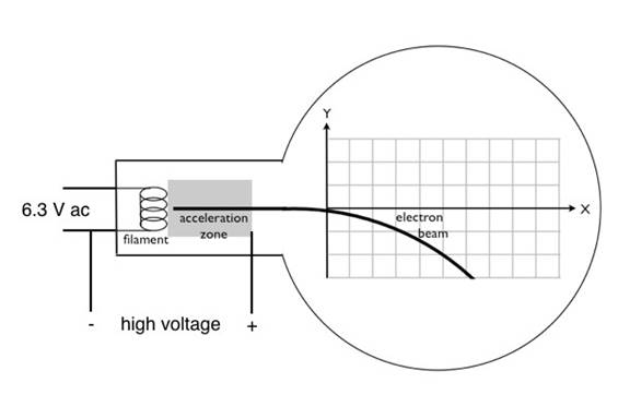
This experiment duplicates J.J. Thomson's famous experiment at the end of the 19th century, in which he measured the charge-to-mass ratio of the electron. In combination with Robert A. Millikan's oil-drop experiment a few years later that produced a value for the charge of the electron, the experiments enabled scientists to find, for the first time, both the mass and the charge of the electron, which are key parameters for the electron.
Thomson was not able to measure the electron charge or the electron mass separately, but he was able to find their ratio. The same is true for this demonstration; although here there is the advantage of being able to look up the values for the magnitude of the charge on the electron(e) and the mass of the electron (me), which are now both known precisely.
Procedure
1. Compensating for Earth's Magnetic Field
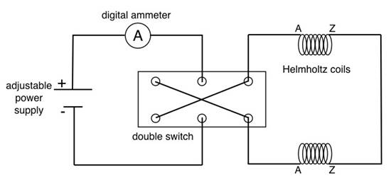
- Note that there are two independent circuits in this experiment:
- Supply current to the coils that create the magnetic field ( Figure 2). The current is set by a rotary dial, and the circuit includes a digital ammeter that allows the current to be measured. A double-pole double-throw switch is used to reverse the direction of the current supplied to the coils, which reverses the magnetic field.
- The second circui
Results
Representative results for Section 2 can be seen in Table 1. Those values give an average charge-to-mass ratio of 1.717 x 10⁻¹¹ C/kg. Note that that is the magnitude of the ratio, because the charge of the electron is a negative value.
Representative results for Section 3 can be seen in Table 1. Those values give an average charge-to-mass ratio of 1.677 x 10⁻¹¹ C/kg. Again,
Application and Summary
This experiment, first performed by J.J. Thomson in the late 19th century, demonstrated the existence of the electron, making it a tremendously important experiment from a historical perspective. Electrons have since been exploited in countless electronic devices.
The following is a list of some applications of charged particles that are traveling in circular or spiral paths, and thus they are traveling in a magnetic field:
1)The formation of the Northern
Skip to...
Videos from this collection:

Now Playing
Electric Charge in a Magnetic Field
Physics II
33.7K Views

Electric Fields
Physics II
77.7K Views

Electric Potential
Physics II
105.3K Views

Magnetic Fields
Physics II
33.7K Views

Investigation Ohm's Law for Ohmic and Nonohmic Conductors
Physics II
26.3K Views

Series and Parallel Resistors
Physics II
33.2K Views

Capacitance
Physics II
43.8K Views

Inductance
Physics II
21.6K Views

RC/RL/LC Circuits
Physics II
143.1K Views

Semiconductors
Physics II
29.9K Views

Photoelectric Effect
Physics II
32.8K Views

Reflection and Refraction
Physics II
36.3K Views

Interference and Diffraction
Physics II
91.4K Views

Standing Waves
Physics II
49.9K Views

Sound Waves and Doppler Shift
Physics II
23.5K Views
Copyright © 2025 MyJoVE Corporation. All rights reserved