
Flyback Converter
Overview
Source: Ali Bazzi, Department of Electrical Engineering, University of Connecticut, Storrs, CT.
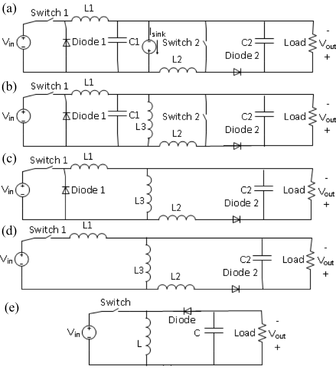
A flyback converter is a buck-boost converter, which can both buck and boost. It has electrical isolation between the input and the output using a coupled inductor or a "flyback transformer." This coupled inductor enables a turns ratio that provides both voltage step-up and step-down capability, like in a regular transformer but with energy storage using the air-gap of the coupled inductor.
The objective of this experiment is to study different characteristics of a flyback converter. This converter operates like a buck-boost converter but has electrical isolation through a coupled inductor. Open-loop operation with a manually-set duty ratio will be used. An approximation of the input-output relationship will be observed.
Procedure
ATTENTION: This experiment is designed to limit the output voltage to be less than 50V DC. Only use duty ratios, frequencies, input voltage, or loads that are given here.
This experiment will utilize the DC-DC converter board provided by HiRel Systems. http://www.hirelsystems.com/shop/Power-Pole-Board.html
Information about the board operation can be found in this collections video “Introduction to the HiRel Board.”
.css-f1q1l5{display:-webkit-box;display:-webkit-flex;display:-ms-flexbox;display:flex;-webkit-align-items:flex-end;-webkit-box-align:flex-end;-ms-flex-align:flex-end;align-items:flex-end;background-image:linear-gradient(180deg, rgba(255, 255, 255, 0) 0%, rgba(255, 255, 255, 0.8) 40%, rgba(255, 255, 255, 1) 100%);width:100%;height:100%;position:absolute;bottom:0px;left:0px;font-size:var(--chakra-fontSizes-lg);color:#676B82;}
Results
Flyback converters are isolated buck-boost converters that can step up or step down the input voltage. The turns-ratio of the flyback coupled inductor or transformer aids in the stepping up or down process. Given that the switching frequency is high, the flyback transformer size is small and uses ferrite cores. If the input voltage is Vin and the output voltage is Vout, Vout/Vin=(N2/N1)D/(
Application and Summary
Flyback converters are typically used in isolated power supplies where the output side should have galvanic isolation from the input side. This is common in driving high-side power semiconductors such as MOSFETs and IGBTs whose gate drive circuits may require isolated DC supplies. Flyback converters are typically operated at high switching frequencies higher than 100 kHz, and have power ratings typically not exceeding 200 W.
Skip to...
Videos from this collection:

Now Playing
Flyback Converter
Electrical Engineering
13.3K Views

Electrical Safety Precautions and Basic Equipment
Electrical Engineering
144.8K Views

Characterization of Magnetic Components
Electrical Engineering
15.1K Views

Introduction to the Power Pole Board
Electrical Engineering
12.5K Views

DC/DC Boost Converter
Electrical Engineering
57.1K Views

DC/DC Buck Converter
Electrical Engineering
21.2K Views

Single Phase Transformers
Electrical Engineering
20.2K Views

Single Phase Rectifiers
Electrical Engineering
23.5K Views

Thyristor Rectifier
Electrical Engineering
17.6K Views

Single Phase Inverter
Electrical Engineering
18.0K Views

DC Motors
Electrical Engineering
23.5K Views

AC Induction Motor Characterization
Electrical Engineering
11.7K Views

VFD-fed AC Induction Machine
Electrical Engineering
7.0K Views

AC Synchronous Machine Synchronization
Electrical Engineering
21.6K Views

AC Synchronous Machine Characterization
Electrical Engineering
14.3K Views
Copyright © 2025 MyJoVE Corporation. All rights reserved