
Single Phase Rectifiers
Overview
Source: Ali Bazzi, Department of Electrical Engineering, University of Connecticut, Storrs, CT.
A DC power supply is generally considered to be a device that supplies DC, or unidirectional, voltage and current. Batteries are one such power supply, however, they are limited in terms of lifetime and expense. An alternative method to providing unidirectional power is to transform AC line power to DC power using a rectifier.
A rectifier is a device that passes current in one direction, and blocks it in the other direction, enabling the transformation of AC to DC. Rectifiers are important in electronic circuits as they only allow current in a certain direction after a certain threshold forward voltage across them is overcome. A rectifier can be a diode, a silicon controller rectifier, or other types of silicon P-N junctions. Diodes have two terminals, the anode and the cathode, where current flows from anode to cathode. Rectifier circuits use one or more diodes that change AC voltages and currents, which are bipolar, to unipolar voltages and currents that can be easily filtered to achieve DC voltages and currents.
Procedure
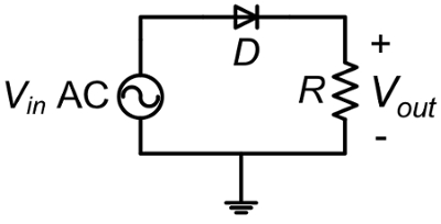
ATTENTION: During this experiment, do not touch any part of the circuit while energized. The AC source is only grounded as shown in Fig. 1 and 2 when the function generator is a source. Do NOT ground the VARIAC.
1. AC Source Setup
For this experiment, two AC sources are used; a variable transformer (VARIAC) at a low frequency of 60 Hz and a function generator with 10 V peak sinusoidal output and 1 kHz frequency.
- Before starting, connect
Results
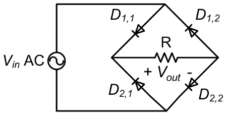
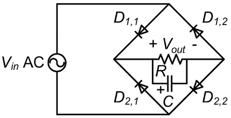
It is expected that a resistive load coupled to a half-wave rectifier will only see the positive half-cycle of the input AC voltage since the diode rectifier can pass current in one direction. With a full-bridge rectifier, the input positive and negative half-cycles are rectified to be positive, but adding a capacitor will filter out most of the voltage ripple and provide the load with a clean DC voltage.
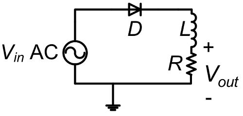
When an inductor is add
Application and Summary
Diode rectifiers are almost in every power supply, charger, variable frequency drive, and in many protection circuits. Most DC power supplies or adjustable AC power supplies use diode rectifiers to convert AC to DC, and then to adjustable AC if needed as in AC power supplies and variable frequency drives. Applications in power electronic converters are common for voltage blocking, and for freewheeling energy in inductors, electro-mechanical relays, and motor windings. Diode applications extend beyond power electronics ap
Tags
Skip to...
Videos from this collection:

Now Playing
Single Phase Rectifiers
Electrical Engineering
23.4K Views

Electrical Safety Precautions and Basic Equipment
Electrical Engineering
144.6K Views

Characterization of Magnetic Components
Electrical Engineering
15.0K Views

Introduction to the Power Pole Board
Electrical Engineering
12.4K Views

DC/DC Boost Converter
Electrical Engineering
56.9K Views

DC/DC Buck Converter
Electrical Engineering
21.1K Views

Flyback Converter
Electrical Engineering
13.2K Views

Single Phase Transformers
Electrical Engineering
20.2K Views

Thyristor Rectifier
Electrical Engineering
17.5K Views

Single Phase Inverter
Electrical Engineering
17.9K Views

DC Motors
Electrical Engineering
23.4K Views

AC Induction Motor Characterization
Electrical Engineering
11.6K Views

VFD-fed AC Induction Machine
Electrical Engineering
6.9K Views

AC Synchronous Machine Synchronization
Electrical Engineering
21.6K Views

AC Synchronous Machine Characterization
Electrical Engineering
14.3K Views
Copyright © 2025 MyJoVE Corporation. All rights reserved