Jet Impinging on an Inclined Plate
Source: Ricardo Mejia-Alvarez and Hussam Hikmat Jabbar, Department of Mechanical Engineering, Michigan State University, East Lansing, MI
The goal of this experiment is to demonstrate how a fluid flow exerts forces on structures by conversion of dynamic pressure into static pressure. To this end, we will make a plane jet impinge on a flat plate and will measure the resulting pressure distribution along the plate. The resultant force will be estimated by integrating the product between the pressure distribution and appropriately defined area differentials along the surface of the plate. This experiment will be repeated for two angles of inclination of the plate with respect to the direction of the jet and two flow rates. Each configuration produces a different pressure distribution along the plate, which is the result of different levels of conversion of dynamic pressure into static pressure at the plate's surface.
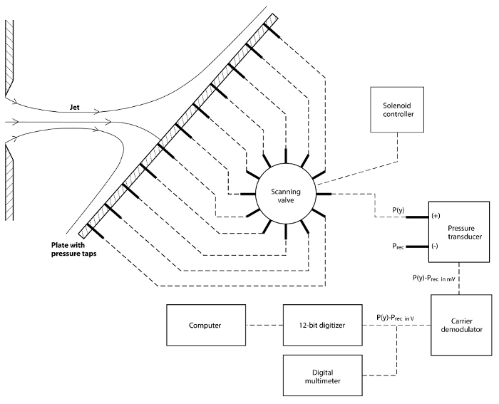
For this experiment, pressure will be measured with a diaphragm pressure transducer connected to a scanning valve. The plate itself has small perforations called pressure taps that connect to the scanning valve through hoses. The scanning valve sends the pressure from these taps to the pressure transducer one at a time. The pressure induces mechanical deflection on the diaphragm that the pressure transducer converts into voltage. This voltage is proportional to the pressure difference between the two sides of the diaphragm.
1. Setting the facility
- Make sure that there is no flow in the facility.
- Set the instruments according to the schematic in figure 2.
- Adjust the plate to the desired angle
 . Record this value in table 1.
 - Measure the jet nozzle width W. Record this value in table 1.
- Measure the plate span L. Record this value in table 1.
- Zero the pressure transducer.
- Note the calibration constant of
Figure 4 shows four sets of results obtained for the plane jet impinging on a plate at two different angles and two different flow rates. In fact, since the low-pressure side of the transducer is opened to the receiver, its readings correspond only to the overpressure  , which are in fact the points shown in Figure 4.
Log in or to access full content. Learn more about your institution’s access to JoVE content here
The experiments featured herein demonstrated the interplay of pressure and velocity to generate loads in objects by means of conversion of dynamic pressure into static pressure. These concepts were demonstrated with a plane jet impinging on a flat plate at two different angles and two different flow rates. The experiments clearly demonstrated that the load is highest at the stagnation point, where all the dynamic pressure is converted into static pressure, and its magnitude decreases as the level of conversion from dynam
- Arnau, A. (ed.). Piezoelectric transducers and applications. Vol. 2004. Heidelberg: Springer, 2004.
- Tropea, C., A.L. Yarin, and J.F. Foss. Springer handbook of experimental fluid mechanics. Vol. 1. Springer Science & Business Media, 2007.
- White, F. M. Fluid Mechanics, 7th ed., McGraw-Hill, 2009.
- Chapra, S.C. and R.P. Canale. Numerical methods for engineers. Vol. 2. New York: McGraw-Hill, 1998.
- Buckingham, E. Note on contraction coefficients of jets of gas. Journal of Research,6:765-775, 1931.
- Munson, B.R., D.F. Young, T.H. Okiishi. Fundamentals of Fluid Mechanics. 5th ed., Wiley, 2006.
- Lienhard V, J.H. and J.H. Lienhard IV. Velocity coefficients for free jets from sharp-edged orifices. ASME Journal of Fluids Engineering, 106:13-17, 1984.
Skip to...
Videos from this collection:

Now Playing
Jet Impinging on an Inclined Plate
Mechanical Engineering
10.7K Views

Buoyancy and Drag on Immersed Bodies
Mechanical Engineering
29.8K Views

Stability of Floating Vessels
Mechanical Engineering
22.3K Views

Propulsion and Thrust
Mechanical Engineering
20.8K Views

Piping Networks and Pressure Losses
Mechanical Engineering
57.8K Views

Quenching and Boiling
Mechanical Engineering
7.7K Views

Hydraulic Jumps
Mechanical Engineering
40.8K Views

Heat Exchanger Analysis
Mechanical Engineering
27.9K Views

Introduction to Refrigeration
Mechanical Engineering
24.6K Views

Hot Wire Anemometry
Mechanical Engineering
15.5K Views

Measuring Turbulent Flows
Mechanical Engineering
13.4K Views

Visualization of Flow Past a Bluff Body
Mechanical Engineering
11.7K Views

Conservation of Energy Approach to System Analysis
Mechanical Engineering
7.3K Views

Mass Conservation and Flow Rate Measurements
Mechanical Engineering
22.6K Views

Determination of Impingement Forces on a Flat Plate with the Control Volume Method
Mechanical Engineering
25.9K Views
Copyright © 2025 MyJoVE Corporation. All rights reserved
 ).
). ).
). (V) associated with the pressure difference between the plenum and the receiver sensed by the pressure transducer. Record this value in table 2.
 ). Record this value on table 2.
 ) of the pressure tap from which plate-pressure data will be acquired. Take into account that the pressure taps are spaced by 25.4mm. Hence, the position will be
  mm, where
  is the index of the tap starting at 0.
 .
.