Confocal Fluorescence Microscopy: A Technique to Determine the Localization of Proteins in Mouse Fibroblasts
Overview
Source: Dominique R. Bollino1, Eric A. Legenzov2, Tonya J. Webb1
1 Department of Microbiology and Immunology, University of Maryland School of Medicine and the Marlene and Stewart Greenebaum Comprehensive Cancer Center, Baltimore, Maryland 21201
2 Center for Biomedical Engineering and Technology, University of Maryland School of Medicine, Baltimore, Maryland 21201
Confocal fluorescence microscopy is an imaging technique that enables increased optical resolution as compared to conventional "wide-field" epifluorescence microscopy. Confocal microscopes are able to achieve improved x-y optical resolution through "laser scanning"- typically a set of voltage-controlled mirrors (galvanometer or "galvo" mirrors) that direct laser-illumination to each pixel of the specimen at a time. More importantly, confocal microscopes achieve superior z-axial resolution by using a pinhole to remove out of focus light originating from locations that are not in the z-plane being scanned, thus enabling the detector to collect data from a specified z-plane. Because of the high z-resolution achievable in confocal microscopy, it is possible to collect images from a series of z-planes (also-called z-stack) and construct a 3D image through software.
Before discussing the mechanism of a confocal microscope, it is important to consider how a sample interacts with light. Light is composed of photons, packets of electromagnetic energy. A photon impinging on a biological sample can interact with the molecules comprising the sample in one of four ways: 1) the photon does not interact and passes through the sample; 2) the photon is reflected/scattered; 3) the photon is absorbed by a molecule and the absorbed energy is released as heat through processes collectively known as nonradiative decay; and 4) the photon is absorbed and the energy is then rapidly reemitted as a secondary photon through the process known as fluorescence. A molecule whose structure permits fluorescence emission is called a fluorophore. Most biological samples contain negligible endogenous fluorophores; therefore exogenous fluorophores must be used to highlight features of interest in the sample. During fluorescence microscopy, the sample is illuminated with light of the appropriate wavelength for absorption by the fluorophore. Upon absorbing a photon, a fluorophore is said to be "excited" and the process of absorption is referred to as "excitation". When a fluorophore gives up energy in the form of a photon, the process is known as "emission", and the emitted photon is called fluorescence.
The light beam used to excite a fluorophore is focused by the objective lens of a microscope and converges at a "focal point" where it is maximally focused. Beyond the focal point the light again diverges. The entering and exiting beams may be visualized as a pair of cones touching at the focal point (see Figure 1, left panel). The phenomenon of diffraction imposes a limit on how tightly a beam of light can be focused - the beam actually focuses to a spot of finite size. Two factors determine the size of the focal spot: 1) the wavelength of the light, and 2) the light-gathering ability of the objective lens, which is characterized by its numerical aperture (NA). The focal "spot" extends not only in the x-y plane, but also in the z direction, and is in reality a focal volume. The dimensions of this focal volume define the maximum resolution achievable by optical imaging. Although the number of photons is greatest within the focal volume, the conical light paths above and below the focus also contain a lower density of photons. Any fluorophore in the light path can thus be excited. In conventional (wide-field) epifluorescence microscopy, emission from fluorophores above and below the focal plane contribute out-of-focus fluorescence (a "hazy background"), which reduces image resolution and contrast, as demonstrated in Figure 1, with the red cube representing fluorophore emission above the focal plane (red star) that results in out-of-focus fluorescence (top right). This problem is ameliorated in confocal microscopy, due to the utilization of a pinhole. (Figure 2, bottom right). As depicted in Figure 3, the pinhole allows emissions originating from the focal place to reach the detector (left), while blocking the out-of-focus fluorescence (right) from reaching the detector, thus improving both resolution and contrast.
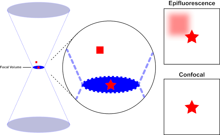
Figure 1. Optical resolution of epifluorescence versus confocal microscopy. Please click here to view a larger version of this figure.
The light beam used to excite a fluorophore is focused by the objective lens of a microscope and converges at a focal volume and then diverges (left). The red star represents the focal plane of a sample that is being imaged while the red square represents fluorophore emission above the focal plane. When capturing an image of this sample using an epifluorescent microscope, the emission from the out-of-focus red square will visible and contribute to a "hazy background" (top right). Confocal microscopes have a pinhole which prevents the detection of light emitted outside of the focal plane, eliminating the "hazy background" (bottom right).
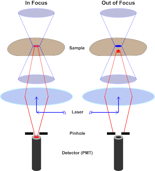
Figure 2. Pinhole effect in confocal microscopy. Please click here to view a larger version of this figure.
Although the highest intensity of the excitation light is at the focal point of the lens (left, red oval), other parts of the sample not in the focal point (right, red star) will get light and fluoresce. To prevent light emitted from these out-of-focus regions to reach the detector, a screen with a pinhole is present in front of the detector. Only the in-focus light (left) emitting from the focal plane is able to travel through the pinhole and reach the detector. The out-of-focus light (right) is blocked with the pinhole and fails to reach the detector.
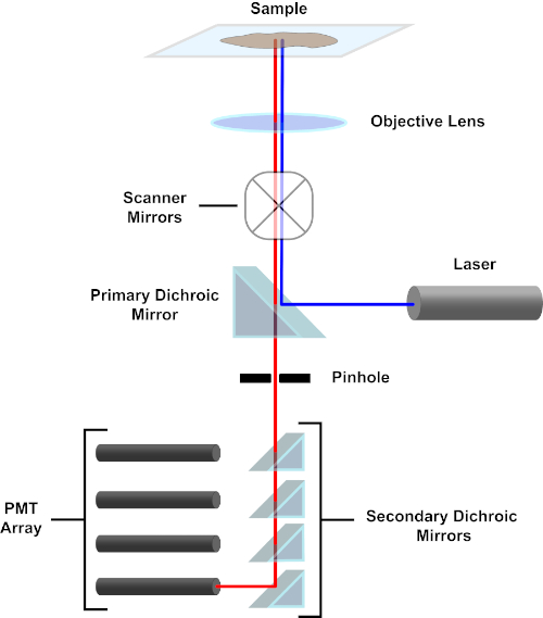
Figure 3. Principal components of a confocal laser scanning microscope. Please click here to view a larger version of this figure.
For the sake of simplicity, the mechanistic description of a confocal microscope will be limited to that of the Nikon Eclipse Ti A1R. Although there may be minor technical differences between different confocal microscopes, the A1R serves well as a good model for describing confocal microscope function. The excitation light beam, produced by an array of diode lasers, is reflected by the primary dichroic mirror into the objective, which focuses the light onto the specimen being imaged. The primary dichroic mirror selectively reflects the excitation light while allowing light at other wavelengths to pass through. The light then encounters the scanning mirrors that sweep the light beam across the specimen in an x-y manner, illuminating a single (x,y) pixel at a time. Fluorescence emitted by fluorophores at the illuminated pixel is collected by the objective lens and passes through the primary dichroic mirror to reach an array of photomultiplier tubes (PMTs). Secondary dichroic mirrors direct the emission light to the appropriate PMT. Excitation light scattered by the sample back into the objective is reflected by the primary dichroic mirror back towards the specimen, and thus prevented from entering the detection light path and reaching the PMTs (see Figure 3). This allows the relatively feeble fluorescence to be quantified without contamination by light scattered from the excitation light beam, which is typically orders of magnitude more intense than the fluorescence. Because the pinhole blocks light from outside of the focal volume, the light arriving at the detector comes from a narrow, selected z-plane. Therefore, images can be collected from a series of adjacent z-planes; this series of images is often referred to as a 'z-stack'. By using the appropriate software, a z-stack can be processed to generate a 3D image of the specimen. A particular advantage of confocal microscopy is the ability to distinguish the subcellular localization of staining. For example, the differentiation between membrane staining from intracellular staining, which is very challenging with conventional epifluorescence microscopy (1, 2, 3).
Sample preparation is an important facet of confocal imaging. A strength of optical microscopy techniques is the flexibility to image live or fixed cells. When attempting to produce 3D images, because of the number of images that must be acquired for a z-stack, the difficulty of maintaining cell health, and the movement of live cells and their organelles, the use of fixed cells is typical. The procedure for fixing and staining cells for confocal fluorescence is similar to that conventionally used in immunofluorescence. After culture in chamber slides or on coverslips, cells are fixed using paraformaldehyde to preserve cellular morphology. Non-specific antibody binding is blocked using bovine serum albumin, milk, or normal serum. In order to maintain the specificity of the secondary antibodies, the solution used should not originate from the same species in which the primary antibodies were generated. The cells are incubated with primary antibodies that bind the antigen of interest. When labeling several cellular targets, the primary antibodies must each be derived from a different species. Antibodies tagging an antigen are then bound by fluorophore-conjugated secondary antibodies. Fluorophore-conjugated secondary antibodies should be selected so that they are compatible with the wavelengths of laser excitation available in the confocal microscope. When visualizing multiple antigens, the excitation/emission spectra of the fluorophores should differ enough so that their signals can be discriminated by microscopic analysis. The stained specimen is then mounted on a slide for imaging. A mounting medium is used to prevent photobleaching and specimen dehydration. If desired, a mounting medium containing a nuclear counterstain (e.g. DAPI or Hoechst) can be used (4).
In the following protocol, mouse fibroblasts transfected to express CD1d (LCD1) were stained with antibodies recognizing CD1d and CD107a (LAMP-1). CD1d is a major histocompatibility complex 1 (MHC 1)-like receptor present on the surface of antigen presenting cells that presents lipid antigens. LAMP-1 (lysosomal associated membrane protein-1) is a transmembrane protein primarily present in lysosomal membranes. For proper antigen presentation, CD1d is trafficked through the low pH lysosomal compartment, so LAMP-1 is being used as a marker of the lysosomal compartment for this protocol. By probing the LCD1 cells with anti-CD1d and anti- LAMP-1 that were produced in different species, secondary antibodies with unique fluorophores can be used to determine the localization of each protein in the cell and whether CD1d is present in the LAMP-1 positive lysosomal compartments.
Procedure
1. Materials
Buffers
- Wash buffer: 1 X sterile phosphate-buffered saline (PBS) without calcium or magnesium
- Fixation buffer: 1% paraformaldehyde in PBS
- Permeabilization buffer: 0.1% Triton X-100 in PBS
- Blocking buffer: 1% bovine serum albumin in PBS
- Cell growth medium: DMEM supplemented with 10% fetal bovine serum (FBS), penicillin/streptomycin, and L-glutamine
Equipment
- Laminar flow hood
- Humidified incubator (37°C, 5% CO2)
- Confocal laser scanning microscope; here, Nikon Eclipse Ti laser
Materials and Reagents
- Chambered cell culture slides
- Anti-fade mounting media with DAPI (for staining nuclei)
- Microscope cover glass
- Delicate task wipes
- Pipettors and tips
Assay Specific Reagents
- Adherent cells (primary cells or cell lines); here, mouse fibroblasts transfected with CD1d were used (LCD1).
- Primary antibodies to detect cellular targets; here, rat anti-mouse CD107a (LAMP-1) and mouse anti-mouse CD1d were used.
- Fluorophore-conjugated secondary antibodies specific to primary antibody isotypes; here anti-rat IgG conjugated to Alexafluor 488 and anti-mouse IgG conjugated to Alexafluor 647 were used.
2. Protocol
Preparing for Antibody Staining
Seeding cells
- Resuspend the cells of interest in growth media.
- Then, seed 500 µL of the cell suspension/per well into the wells of a 4-well chamber slide. (Here, LCD1 cells were seeded at 2.5x10⁵ cells/chamber in 500 µL of growth media. The seeding density may vary between cell lines).
- Incubate the chamber slide overnight in a 5% CO2 incubator at 37°C, to allow cells to adhere to the glass.
- Next day, aspirate the media from each well and then wash the cells 1X with 500 µL PBS.
Fixation
- To fix the cells, add 500 µL 1% paraformaldehyde solution into each well and incubate for 15 min at room temperature.
- After the incubation, collect the paraformaldehyde into an appropriate hazardous liquid waste container.
- Then, wash the cells 3 times with 500 µL PBS to remove any remnants of the fixative.
Permeabilization
- Permeabilize the cells by incubating with 500 µL permeabilization buffer/well for 15 minutes at room temperature.
- Then, wash the cells briefly 3 times with 500 µL of PBS.
Blocking
- Incubate the cells in each well with 500 µL blocking buffer for 1 hour at 4°C, to block non-specific antibody binding.
Primary Antibody Incubation
- Aspirate the blocking buffer from the slide chambers.
- Then, add 500 µL of diluted primary antibody solution to cells. (Here, anti-CD107a (LAMP-1) was diluted 1:500 and anti-CD1d was used undiluted (1H6 monoclonal antibody was kindly provided by Dr. Randy Brutkiewicz)).
- Incubate the slides overnight at 4°C.
Note: If probing for more than one target, make sure that the primary antibodies are different isotypes. Recommended antibody concentrations vary between manufacturers and should be titrated prior to use.
Secondary Antibody Incubation
- Aspirate the primary antibody solution from the wells.
- Wash the well chambers 4 times with 500 µL PBS.
- Then, add 500 µL of the diluted secondary antibody solution to each well. (Here, both the secondary antibodies- anti-mouse IgG Alexafluor 647 and anti-rat IgG Alexafluor 488 were diluted 1:2000 in the blocking buffer).
- Incubate at room temperature for 1 h in the dark.
- After the incubation, aspirate the secondary antibody solution.
- Wash the chambers 4 times with 500 µL PBS to remove any unbound secondary antibody.
Note: Recommended antibody concentrations vary between manufacturers and should be titrated prior to use. If probing for more than one target, secondary antibodies must be conjugated to different fluorophores with unique excitation/emission spectrums. Also keep in mind the excitation/emission of the nuclear counterstain (i.e. DAPI) while selecting the fluorophores. Fluorophore selection may be impacted by the laser configuration of the confocal microscope used. The laser configuration of the machine will dictate which fluorophores are suitable for the experiment.
3. Mounting Coverslips
- First, carefully remove the chambers from the slide.
- Then, hold the slide at angle over a delicate task wipe and remove the fluid from the edges without touching the cells.
- Add 1 drop of antifade mounting medium, containing the nuclear stain DAPI, onto each section of cells.
- Next, place a 20 mm x 60 mm coverslip over the slide by holding it over the edges using the fingertips. (Avoid bubble formation over the cells, as they interfere with imaging).
- Wipe off any extra mounting medium on the sides with a delicate task wipe and store the slides in the dark at room temperature up to a week.
4. Confocal Imaging
Image samples on a confocal laser scanning microscope. For data shown in Figure 2, the Nikon Eclipse Ti A1R was used with NIS Elements Advanced Research software. The following section details the procedure for capturing images using the aforementioned software.
- To begin imaging the cells, open the 'NIS Elements Advanced Research software' by clicking on the 'NIS software icon.'
- Next, on the control window click on 'TiPad' tab and choose the desired objective for imaging. (Here, first 40x objective was used).
- Load the slide with cells onto the stage and center it beneath the lens.
- Now, on the 'A1plus Compact GUI' tab, set up the lasers appropriate for the fluorophores used. Click on the gear symbol to open the dye and spectral settings menu and select the channels needed and set the laser for each channel.
- Then, select the appropriate emissions in the dropdown menu under the first dichroic mirror.
- Next, under 'A1plus Compact GUI' window, click on 'Ch. Series' to set up the line channel series, which sets up whether the lasers used will fire on the sample simultaneously or sequentially. (Here, sequential passes were chosen, starting with channel 1, followed by channel 2, then 4).
- After that, start scanning by clicking the 'Arrow tip' icon on the top. At this point while the imaging is live, under 'A1plus Compact GUI' window, click on the sliding scale and modify the pinhole size to assure limiting out of focus light. (Here, the lowest available setting (0.5), was used).
- Next, adjust the 'high voltage' and 'offset' settings under each laser to appropriate levels, by using the sliding scales to enable detection of the specific staining while limiting any potential background staining. If a positive-staining sample is available, start by imaging this sample for each channel to make sure the laser settings yield optimal signal to noise ratios.
Caution: high laser intensity for extended periods can cause photobleaching. - After setting the optimal HV and offset values for each laser, click on the 'ND Acquisition tab'and then select the 'Z' icon to set up the parameters for the z-series. Next, while acquiring a live image of the sample, first set the bottom by finding the bottom of the image and clicking the 'bottom' button then find the top position of the sample and click the 'top' button. Set the step size either by specifically typing the preferred step size in µm for each step or by specifying how many total steps are needed.
- Once the z-series parameters have been set, select the desired size/pixel resolution of the image. To do so, click the 'A1plus Compact GUI' window and under the 'size' icon select the desired resolution. To decrease the noise of the image, one can select the dropdown menu next to the 'ø' symbol to average the selected number of images.
- Now, click the 'Run now' tab on the 'ND Acquisition menu' in order to start imaging the sample.
- After imaging is complete, save the image by clicking 'File', then 'Save As', which will export the image file with the extension '.nd2'. Finally, repeat the process for each of the other samples.
Results
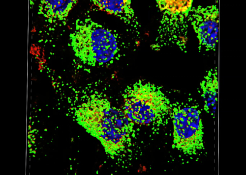
In this experiment, mouse fibroblasts expressing the surface glycoprotein gene CD1d were fixed, immunostained and imaged on a confocal microscope. A representative image obtained using the above protocol is shown in Figure 4. In the top panel of A, single-channel images showing the staining pattern of each individual target are presented. These images comprise a single section (slice) of the z-stack captured. The right panel shows DAPI staining of nuclei of the cells. The center panels show CD1d stained in red and LAMP-1, a lysosomal marker, stained in green. The left panel is a composite image where the three different channels are merged. The appearance of yellow results from overlap of the red and green channels, and indicates an area where CD1d and LAMP-1 are co-localized. The results of the staining confirm that CD1d is localized in the LAMP-1+ endosomal compartments. There are also areas where only one color is present, which indicates the presence of CD1d or LAMP-1 without co-localization. The bottom panel of A shows a 3D rendering of the cells constructed from images captured in the z-stack.
Panel B shows a slice out of the z-stack at 100x magnification demonstrating the expression patterns of these two proteins in greater detail. The pink outlined box on the right side of the image displays the cross section of the x-coordinate designated by the pink line in the image, which represents the side view at the pink line. Similarly, the blue outlined box on the bottom of the image shows the cross section of the y-coordinate designated by the blue line in the image, which represents the front view at the blue line. The 3D rendering of the z-stack image enables users to view the image in 3D, visualizing all the x, y and z planes.
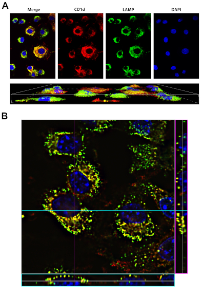
Figure 4: Staining of CD1d and LAMP1. Please click here to view a larger version of this figure.
A, top panel: LCD1 cells were fixed, permeabilized and stained with antibodies to CD1d (red) and LAMP-1 (green, a marker of the lysosomal compartment). DAPI (blue, was used to visualize the nucleus). The merge (left panel) shows that CD1d is localized in the LAMP-1 positive late endosomal/lysosomal compartment (yellow).
A, bottom panel: 3D rendering of the same cells in top panel. Images were acquired using a 40x oil-immersion objective on the Nikon Eclipse Ti, using the NIS Elements Advanced Research software.
B: 100x image of LCD1d cells stained as in A, with stack information for a particular y-coordinate (denoted by the blue line) on the bottom of the image (blue box). The stack information for a particular x-coordinate (denoted by the pink line) is shown on the right side of the image (pink box).
Application and Summary
Confocal fluorescent staining is a relatively simple procedure that results in extremely high-quality images of specimens that are prepared in a similar way as for conventional fluorescence microscopy. In brief, samples are fixed, permeabilized, then blocked. Primary antibodies against a protein or proteins of interest are allowed to bind, then fluorophore-conjugated secondary antibodies are used to visualize the staining. Confocal fluorescence microscopy has applications in many areas of research. For example, by staining for markers of sub-cellular organelles along with a protein of interest, confocal microscopy can be used to determine the subcellular locations of diverse proteins. Compared to conventional fluorescence microscopy, confocal imaging can more effectively distinguish between cell surface and intracellular location of a protein. In addition, confocal imaging can also be used to determine whether two proteins co-localize within the cell. Although not outlined in this protocol, confocal fluorescence microscopy also can be performed on live cells to detect dynamic changes.
Video 1: Video created in NIS Elements Advanced Research software, highlighting the ability to move through the 3D rendering of the images. Please click here to view this video (Right click to download).
References
- Claxton, N. S., Fellers, T. J. and Davidson, M. W. Laser scanning confocal microscopy. Department of Optical Microscopy and Digital Imaging, National High Magnetic Field Laboratory, Florida State University, 37 p., Unpublished (2010). Available at- http://www.vertilon.com/pdf/PP6207.pdf.
- Ojcius, D. M., Niedergang, F., Subtil, A., Hellio, R. and Dautry-Varsat, A. Immunology and the confocal microscope. Research in Immunology, 147 (3),175-88 (1996).
- Paddock, S. W. and Eliceiri K. W. Laser scanning confocal microscopy: history, applications, and related optical sectioning techniques. Methods in Molecular Biology, 1075, 9-47 (2014).
- Hoff. F. How to prepare your specimen for immunofluorescence microscopy. Philipps University Marburg, Institute of Cytobiology and Cytopathology, Germany. (2015) Available at- http://www.leica-microsystems.com.
Tags
Skip to...
Videos from this collection:

Now Playing
Confocal Fluorescence Microscopy: A Technique to Determine the Localization of Proteins in Mouse Fibroblasts
Immunology
43.0K Views

Flow Cytometry and Fluorescence-Activated Cell Sorting (FACS): Isolation of Splenic B Lymphocytes
Immunology
92.5K Views

Magnetic Activated Cell Sorting (MACS): Isolation of Thymic T Lymphocytes
Immunology
22.7K Views

ELISA Assays: Indirect, Sandwich, and Competitive
Immunology
236.8K Views

ELISPOT Assay: Detection of IFN-γ Secreting Splenocytes
Immunology
28.3K Views

Immunohistochemistry and Immunocytochemistry: Tissue Imaging via Light Microscopy
Immunology
78.5K Views

Antibody Generation: Producing Monoclonal Antibodies Using Hybridomas
Immunology
43.3K Views

Immunofluorescence Microscopy: Immunofluorescence Staining of Paraffin-Embedded Tissue Sections
Immunology
53.6K Views

Immunoprecipitation-Based Techniques: Purification of Endogenous Proteins Using Agarose Beads
Immunology
87.4K Views

Cell Cycle Analysis: Assessing CD4 and CD8 T Cell Proliferation After Stimulation Using CFSE Staining and Flow Cytometry
Immunology
24.1K Views

Adoptive Cell Transfer: Introducing Donor Mouse Splenocytes to a Host Mouse and Assessing Success via FACS
Immunology
22.1K Views

Assay for Cell Death: Chromium Release Assay of Cytotoxic Ability
Immunology
151.4K Views
Copyright © 2025 MyJoVE Corporation. All rights reserved