
Method Article
为记录细胞内电压响应电法
摘要
Sharp microelectrodes enable accurate electrophysiological characterization of photoreceptor and visual interneuron output in living Drosophila. Here we show how to use this method to record high-quality voltage responses of individual cells to controlled light stimulation. This method is ideal for studying neural information processing in insect compound eyes.
摘要
Voltage responses of insect photoreceptors and visual interneurons can be accurately recorded with conventional sharp microelectrodes. The method described here enables the investigator to measure long-lasting (from minutes to hours) high-quality intracellular responses from single Drosophila R1-R6 photoreceptors and Large Monopolar Cells (LMCs) to light stimuli. Because the recording system has low noise, it can be used to study variability among individual cells in the fly eye, and how their outputs reflect the physical properties of the visual environment. We outline all key steps in performing this technique. The basic steps in constructing an appropriate electrophysiology set-up for recording, such as design and selection of the experimental equipment are described. We also explain how to prepare for recording by making appropriate (sharp) recording and (blunt) reference electrodes. Details are given on how to fix an intact fly in a bespoke fly-holder, prepare a small window in its eye and insert a recording electrode through this hole with minimal damage. We explain how to localize the center of a cell's receptive field, dark- or light-adapt the studied cell, and to record its voltage responses to dynamic light stimuli. Finally, we describe the criteria for stable normal recordings, show characteristic high-quality voltage responses of individual cells to different light stimuli, and briefly define how to quantify their signaling performance. Many aspects of the method are technically challenging and require practice and patience to master. But once learned and optimized for the investigator's experimental objectives, it grants outstanding in vivo neurophysiological data.
引言
果蝇( 果蝇 )复眼是一个伟大的模型系统来研究神经图像采集和处理感光和中间神经元阵列的功能组织,以及对动物的视力。该系统具有最完整的接线图1,2和是可亲到遗传操作和准确的神经活动监测3-10(高信噪比和时间分辨率)。
果蝇眼睛是模块化的,含有〜750看似普通镜头覆盖的结构,称为小眼,它们共同提供悬挂该占地约它的头几乎每一个方向的全景视野。眼睛的主要信息抽样单位是其rhabdomeric感光7,8,11。每个小眼包含八个感光细胞(R1-R8),它们共享相同的小面透镜,但被对准至七个不同的方向。虽然外光感受器,R1-R6芳E要蓝绿光最为敏感,内细胞R7和R8,它趴在对方并指向同一方向的顶部光谱灵敏度,表现出三个不同的亚型:面色苍白,黄色,背缘区(DRA)12 15。

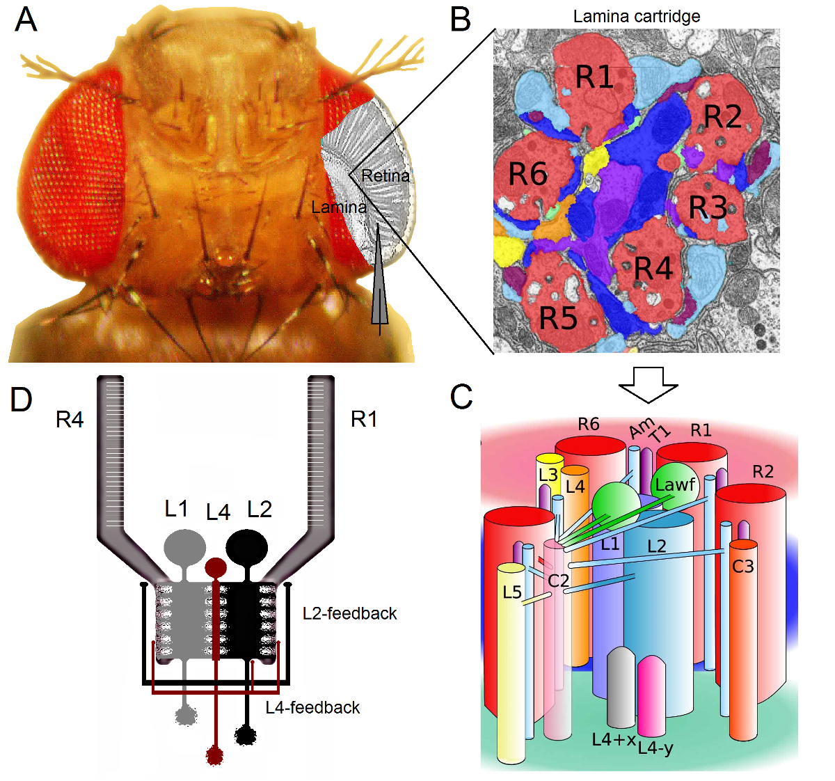
图 1. 果蝇 眼睛 的功能性组织 。 (A)的两个第一视神经节,视网膜和椎板,以灰色突出显示的蝇眼内。视网膜R1-R6感光细胞和叶片大单极细胞(低收入国家:L1-L3) 在体内常规尖锐的微电极记录容易接近。示意图电极突出,从R1-R6在视网膜记录正常轨道。从低收入国家在椎板记录之一路径是平行的电极转移到左。 (B)叶片是retinotopically器官的矩阵源化墨盒,其中的每一个填充有从在视觉空间中的特定的小区域处理信息的神经元。由于神经叠加,从不同的相邻小眼感光器6送他们的轴突(R1-R6)相同的椎板墨盒,形成组胺输出突触L1-L3和无长突细胞(AM)。 (C)的R1-R6轴突和视觉的interneurons(包括L4,L5,Lawf,C2,C3和T1),内筒层是复杂的神经之间的信息的传播。 (D)R1-R6感光轴突接收来自L2和L4单极细胞突触的反馈。从里维拉阿尔巴等2修改(B)和(C)。 请点击此处查看该图的放大版本。
果蝇眼睛是神经叠加16型。该装置T椎板和髓质:帽子八感光属于7相邻小眼,看起来在空间中的相同点的神经信号,以在接下来的两个髓神经1墨盒汇集在一起。而六个外光感受器,R1-R6项目其轴突末梢神经列在薄片( 图1)中,R7和R8细胞绕过此层,并与它们的相应髓质柱17-19突触联系。这些精确的连线生产用于飞行的早期视觉的视皮层映射神经基板,于是每一个叶片( 图1A-C)和髓质柱(盒)代表在空间中的一个点。
和无长突细胞(AM)在椎板1,2,20:从R1-R6感光体直接输入由大单极细胞(L1,L2和L3低收入国家)接收。出的这些,L1和L2是最大的细胞,介导主要信息通路( 图1D),WHI通道响应于接通和关断移动边,并由此形成所述运动检测器21,22的计算基础。行为实验表明,在中间的对比,这两种途径促进相反方向的运动知觉:后端到前在L1和前到后在L2细胞23,24。连接进一步表示:L4神经元可能在相邻的墨盒25,26之间的横向沟通起到至关重要的作用。位于同一L2和L4细胞和两个相邻盒之间发现倒数突触。下游,每个L 2小区和它的三个相关联的L4细胞投射它们的轴突到公共目标,在髓质,其中来自相邻墨盒输入信Tm2的神经元被集成为前到后运动27的处理。虽然L1的神经元通过两个间隙连接和突触接收来自同一盒L2S输入,它们不直接连接到L4S因此相邻薄层墨盒。
被属于在L2 / L4电路的神经元只提供突触反馈到R1-R6感光轴突,但不用L1通路1,2( 图1D)。虽然同一墨盒连接从L2至R1和R2以及从L4到R 5是选择性地,所有的R 1〜R 6的光感受器接收来自任L4或两个相邻的墨盒一样的反馈。此外,还有从上午到R1,R2,R4和R5强突触连接,和神经胶质细胞也突触连接到网络,因此可参与神经图像处理6。最后,轴突间隙路口,连接在相邻的层R1-R6和R6和R7 / R8之间的光感受器,有助于信息不对称表示和处理每个墨盒14,20,28。从在几乎完整的果蝇个体感光细胞和视觉的interneurons细胞内电压记录提供高的信号-噪音r在亚毫秒分辨率3,5,7-10,29,这是必要用于使连接的神经元之间的快速的神经计算的感ATIO数据。的精度这一级是由目前的光成像技术,这是显著喧闹并且通常在10操作是不可能的 - 100毫秒的分辨率。此外,因为电极具有非常小的和尖锐的提示,该方法不限于细胞体,但可提供从小活性神经结构直接记录;如低收入国家'树突树木或感光体轴突,这是不能由大得多膜片钳电极的前端访问。重要的是,该方法也是在结构上比大多数膜片钳应用侵入性较少,并毁坏等影响少的研究细胞的细胞内环境和信息抽样。因此,传统尖锐的微电极技术作出了贡献,并继续做出贡献,根本发现和原来的洞察神经Infor公司在适当的时间尺度息处理;提高我们的愿景3-10的机械理解。
本文介绍了如何从 果蝇 R1-R6感光细胞和低收入国家体细胞内记录在Juusola实验室中进行。该协议将介绍如何构建一个合适的电装备,准备飞行,并进行录音。一些有代表性的数据被呈现,并且一些共同的问题和潜在的解决方案进行了讨论,可能使用该方法时会遇到。
研究方案
下面的协议与所有谢菲尔德大学和北京师范大学的动物护理准则。
1,试剂和设备的准备
- 记录光刺激设备安装
- 选择至少在有管制的湿度空调和手段,提供深色记录条件的房间进行电生理实验一2.5×2.5 M个记录区域。确保这个面积足够大,舒适适合:(一)1×1米的振动隔离表,里面的装备[飞刺激和记录装置],体视显微镜和冷光源两鹅脖子,全封闭式内大"180厘米高的法拉第笼; (二)一个38U机架设备对住房的个人电脑一台液晶显示器,功放微电极,LED驱动器,过滤器,温度控制单元,示波器等所需的电子仪器;和(iii)一小书桌和研究者的椅子上。
- 放置钻机远离电气和机械的噪声源,如冰箱,离心机和电梯。使用单独的浪涌保护器,以保护装备的电子设备在电网发生电压尖峰。理想情况下,连接钻机自己的不间断电源(UPS电池),以尽量减少噪音。
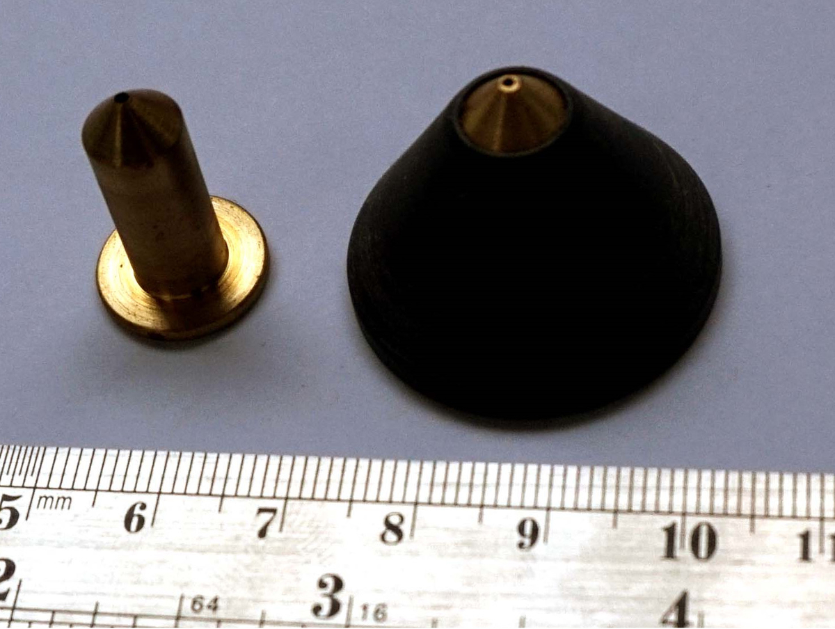
- 构造一个圆锥形飞架从黄铜和黑色塑料( 图2)。钻透黄铜单元的小锥形孔与外部边框变窄〜直径0.8mm(匹配一个典型的苍蝇的胸部宽度)。
注意:此孔需要朝向蝇刀柄的前端锥度,使得比平均果蝇 ,这是从下面的气流伸出,较大会卡住肩深在顶部边缘。 - 设计和建造一个机械健壮,而精确,飞刺激和记录装置( 图3)。构建出Ø˚F铝或黄铜(高导电性金属)苍蝇制备平台极和它周围的万向臂系统,具有嵌入球轴承,以提供平滑和准确的x,y定位和光刺激的锁定。
注:该集成复合设计的机械振动,这本来从细胞研究打跑出来的记录电极尖端降至最低。它可以进一步将一个基于珀尔帖元件闭环温度控制系统,使研究者使用温度敏感的遗传构建体,如shibire 的TS,以评估突触电路计算9,30。阳极氧化设备,或者把它涂黑,以尽量减少光刺激散射。- 固定在防振台的线路板飞刺激和记录装置;例如,通过M6螺栓,利用其度量的螺丝孔。使用黑色面包板或覆盖它与黑色面料在实验过程中,尽量减少光散射。
- Position和锁定(使用锁定螺丝),在万向臂系统的中心垂直可调粉煤灰制备平台极。放置飞制剂(飞夹持器内,见步骤2)在平台磁极,使得附连到万向接头臂光源径向指向该飞的头。确保蝇眼的中心恰好在交点(0,0)的万向接头臂的x轴和y轴,作为这使得准确的x,光刺激的y定位任意点中的苍蝇的视野。
注:此功能是必要的映射单个细胞对特定眼位置的响应性能; 例如 ,对于结构调整,如明亮或急性区,这将显示为31提高了灵敏度和分辨率,电生理证据搜索时。
- 安装在防振动台飞刺激后面的体视显微镜和记录装置,以便它提供的蝇眼舒适的高倍率观看。
- 安装在与所述光源的双头半刚性鹅颈光导朝下朝向蝇制备支架显微镜顶部的冷光源。可自由移动的双光束照射,使经过一个小口进入蝇眼驾驶时它更容易直观地记录电极尖端。
- 附加的适当的x,y,z轴显微组(粗&精),用于在记录电极与防振台头阶段,在飞刺激和记录设备的右侧,用M6螺栓或磁站立。
注意:在Juusola实验室,不同钻机装有不同操纵器;有关详细信息,请参阅材料与试剂的表。这些都提供高品质的细胞内记录。 - 挂载参比电极座小手册3轴显微操纵器上的垂直可调˚FLY准备平台极。定向参考电极,以便它被朝向蝇制备指向。
- 构造一个独立的光屏蔽法拉第笼出钢板的周围的防振台,包围飞刺激和记录装置,以避免外界的电磁干扰。离开笼子开放的前部,提供便利的运输进行实验飞行准备。在前面附上黑色面料的窗帘(有铜或铝网格内植入他们接地)屏蔽了噪音和光。漆笼黑色的内饰,以减少光散射和螺栓笼的脚在地板上,以防止振动。
- 电压和高阻抗的细胞内微电极放大器的电流输出连接到的采用BNC电缆两个单独的低通滤波器(贝塞尔或类似)的输入。同样,滤波器的输出连接到AD-连接器一个BLO的适当的渠道中正/数据采集系统(DA / AD卡)的板。对DA / AD卡(S)连接到由专门的电缆在个人计算机,根据供应商的手册。
- 对于所选择的个人计算机上的数据采集系统安装适当采集软件。保证数据采集驱动程序与操作系统的个人计算机上兼容。
- 地电飞刺激和记录装置,法拉第笼,铜网(窗帘内),显微镜,显微操作,冷光源,38U设备机架中的所有仪器(细胞内放大器,滤波器,温度控制单元,PC和LCD显示器等),通过使用设备接地线和M6压接环接地端单一的中央接地点。使用电万用表测试,所有的部件都在同一个地面。
注意:要实现最佳的低噪声记录条件,接地配置通常来回变化M中的建立到另一个。- 如果需要的话,还连接中央接地点到建筑地,和/或微电极放大器的中央接地。在实际电生理实验测试充分运作系统后,准备根据需要,以减少在记录噪声来改变接地配置。
- 配置软件的扩增(1 - 10X),信号滤波(设定为500赫兹,这是适合于R 1 -R 6和LMC数据通常是低通滤波器),和采样率(至少为1千赫兹)。确保设置服从采样定理32;例如,采集数据是当低通滤波,在500赫兹,用1千赫兹或更高的采样频率以最小化混叠效应。
- 作为R1-R6光感受器的特征电压反应是40 - 65毫伏,而那些低收入国家20 - 45 mV时,设定放大和显示相应缩放,使高分辨率sampliNg和数据可视化。

图2. 锥形粉煤灰保持器的飞支架做出来的两片:中央黄铜单元及其锥形黑色塑料外套。黄铜单元内部的中心孔逐渐变细到一个小直径勉强通过让苍蝇。 请点击此处查看该图的放大版本。

图 3. 电钻机的综述。该集式包含一个独立的光屏蔽法拉第笼,防振台,苍蝇刺激和记录装置,以及黑色织物的窗帘用铜或内部铝网为接地。该插件trument架电连接到与法拉第笼里面所有的设备相同的中央地面上。 请点击此处查看该图的放大版本。
- 微电极制造
- 从filamented硼硅酸盐拉基准微电极(外径1.0毫米;内径0.6毫米)或石英玻璃(外径1.0毫米;内径0.5,0.6mm或0.7mm)使用移液管牵拉仪器管。努力实现短锥渐变。
注:移液器拉马计划的确切设置仪器之间的不同;更多的细节材料与试剂的表。在前端的孔径不是至关重要的,因为参考电极的前端将被插入到飞准备之前被打破。 - 拉从filamented硼硅酸盐(外径记录微电极1.0毫米;内径0.6毫米)或石英玻璃(外径1.0毫米;用移液管牵拉仪器管内径0.5,0.6mm或0.7mm)。努力实现长期(10 - 15mm)的罚款逐步锥度。
- 光学显微镜的记录电极显示正确的减量检查。安装在具有可塑造胶布载玻片上电极,并使用40X空中目标检查其尖端。
注意:好极顺利变细,直到它的看不见的小尖,在其周围连续平行较暗和较亮的干扰模式就可以看出。有些车夫设置产生高电阻的电极,因为他们的技巧像"小号",它不能产生成功的细胞渗透。因此,电极的目视检查是很重要的。 - 水平连接电极上的大培养皿用橡皮泥(或类似的可塑造胶布),用于保管和运输的电钻机。确保电极的提示空气中的总重,不小心触碰任何东西。
- 回填记录和参考电极只是用适当的盐溶液中的实验之前。使用小5毫升注射器连接到小颗粒过滤用细塑料尖(诸如微加载)。
- 对于光感受器实验,填补3米氯化钾额满为止的记录电极(在其大底液滴的形式),因为这解决方案最小化液体接界电势的所记录的电压的影响。
- 为了研究组胺低收入国家,其中以由氯乙烯 - 电导变化从R1-R6光感受器突触输入响应,填充用3M乙酸钾和0.5mM氯化钾的记录电极,因为该解决方案对电池的氯化物电池的影响较小。填充飞林格氏参考电极,含有以mM:120氯化钠,5氯化钾,10 TES(C 6 H 15 NO 6 S),1.5氯化钙2,4的MgCl 2,和30蔗糖 5。
- 测试在记录系统中的新拉出记录电极的电阻。
- 确保该电极托架内的银线被均匀地涂有氯化银(出现紫灰色 - 没有光泽银色),以最大限度地减少记录伪影(例如,在结电位漂移)。如果没有,用正确氯化电线替换它们。
- 如果需要,氯化银新线。仔细清洗线(通过快速并使它们通过火焰),使这些出现在颜色亮银色。避免用手指触摸它们,以一层均匀的氯化银上沉积。浸泡在充满力量的家用漂白剂的电线15 - 30分钟,直到他们出现紫灰色。可替代地,电镀各金属丝(通过使正相对于含有3M氯化钾的溶液,并在1mA表面积/ cm 2的速率使电流通过它)10 - 15秒,直到充分地包衣。
- 背面填充记录和参考电极连接到其电极托架。放置一个小的林格氏液浴的垂直可调粉煤灰制备平台极。驱动电极尖端进入林格氏液和测量记录电极的尖端性。
注:测试电极,这是从一批新的玻璃管,或通过优化迭代中的拔微仪器程序时拉电阻特性时,才需要这一步。 - 在进行电阻测量之前,请阅读放大器制造商的用户手册中的说明相应的测量设置。对于一个好的记录电极,具有约100的端阻力 - 220MΩ。
- 从filamented硼硅酸盐拉基准微电极(外径1.0毫米;内径0.6毫米)或石英玻璃(外径1.0毫米;内径0.5,0.6mm或0.7mm)使用移液管牵拉仪器管。努力实现短锥渐变。
2.准备果蝇
- 收集5 - - 10日龄蝇(羽化后),并放置在含ST干净飞管昂达尔食物。能够实现良好的记录从年轻蝇太,即使从"新生儿";但由于其柔软的眼睛的,切割用于记录电极角膜开口是比较困难的。
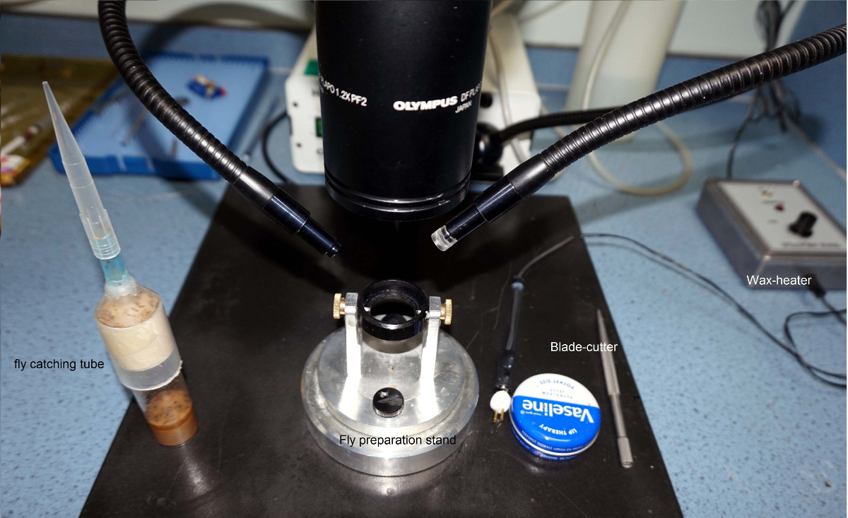
- 构造一个捕蝇管和粉煤灰制备站( 图4)。参见图4的这些自制工具是如何结合在一起的总体思路。
- 为了让苍蝇捕管,切断50毫升的塑料离心管的锥底尖。然后,将和胶水1毫升枪头大底在这个新的开放。
- 最后,切吸管的小端的大小是很容易让一只苍蝇穿行。请教机械车间组装,使2轴旋转和飞持有人不同的位置锁定一个小苍蝇准备阶段。

FIGURË4. 工具并制定所需的制作粉煤灰制备。飞捕管通过胶粘1毫升的塑料枪头50ml塑料离心管中进行。定制蝇制备支架使得能够制备飞优选位置自由旋转和飞保持器的锁定。飞由蜂蜡固定,使用电动蜡加热器。凡士林是由连接在手柄上的厚厚的毛排序做了一个小涂布器。 请点击此处查看该图的放大版本。
- 收集在1ml枪头,它几乎没有使苍蝇,以适应通过实验苍蝇。附加蝇捕捉管中,用在其上的吸移管尖,以飞行管。在追赶一只苍蝇,把他们的内在趋势的优势,向上攀登(antigravitaxis)到枪头。最好选择最大的女性,如大小事S IN电。
注意:飞越大,越大其细胞和更好的高品质细胞内记录的机会。小蝇(包括男性和女性)也能提供优良的记录,但在制备是使更加困难。一旦苍蝇被困在一个大的枪头,记得关闭飞管逃跑阻止其他苍蝇。 - 连接100毫升注射器用柔性的塑料软管枪头较大开口 - 与飞还在呢。
- 放置在大枪头,它被放大只是为了通过让一个果蝇窄端,以在飞保持器的底部的开口,并从注射器挤出的空气的小体积以喷射飞入蝇支架。
- 看通过立体显微镜和直到飞的头从飞支架的锥形端突出轻轻管理更多的空气。确保飞坚定地从其胸部被困的小OPE宁飞保持器的顶部。
- 使用蜡加热到其"肩膀"来飞架固定蜂蜡飞。调整蜡加热器的温度是尽可能低但干净熔化蜡。
注意:当温度是正确的时,蜡会出现透明。过高的温度使得蜡"烧掉"太低保持蜡僵硬。当固定飞,准确,简要作为长期受热可能会损坏它。使用光固化牙科胶这里不推荐作为其应用太慢。

图5. 准备飞 的体内 实验。左 , 果蝇的头部被飞持有人直接定位,并从它的长鼻,右眼和肩部固定带加热是飞持有人eswax 对 ,一个小开口被切断的眼睛最厚的部分,只是在赤道,只有少数小眼从背面角质层远以上,用锋利的剃刀边缘。一块角膜轻轻去除,孔与凡士林,防止眼睛干涸密封。 请点击此处查看该图的放大版本。
- 固定苍蝇的头。适用蜂蜡的长鼻( 图5)和右眼角,避免了角膜,并从这些分飞保持器固定的头部。
- 生产微型刀。钳位非不锈钢剃刀刃带两个刀座/断路器(均为平坦的抓地力),并破解其锐利边缘的一小片。为了健康和安全,请使用保护眼睛护目镜(即使它是极不可能的,当剃刀被破解件会弹)。理想情况下,产生类似于一个塔尖锋利的剃刀边缘。确保这个"塔尖"牢固地连接到刀片持有人,但要小心,以避免自伤!
- 在约4 - - 使用微小刀,准备在苍蝇的左眼几个小眼的一小开口尺寸从背角质层只是眼睛的赤道上空5小眼,以提供用于记录微电极的通路。立体显微镜下进行,查看用高倍率的准备。
注意:由于蝇眼感觉弹性和电阻来探测,洞是一个"塔尖"γ-刀最佳切割。切割技术是相当具有挑战性,因此要密切关注视频演示。保持在一定的方位飞持有人(在飞准备支架)可以使清扫更容易。最初,显微可能会觉得难学,但一旦承诺,神经适应逐步改善研究者的3D感知和灵巧。 - - [Remove仔细小块从开业角膜刚切开,露出下面的视网膜。迅速盖上使用凡士林涂抹器的汗毛凡士林的一个微小的斑点在眼睛的孔中。
注:凡士林这里提供多个角色。它可以防止组织脱水,这会打破插入记录电极血淋巴中的凝血。它也顺便涂覆微电极,降低其壁间电容。这样可以提高在记录系统的频率响应,所以所记录的神经信号的时间分辨率。避免过度眼的其余部分涂抹凡士林作为此模糊的光学器件。
3.从R1-R6光感受器或低收入国家记录
- (通过触摸法拉第笼或抗振动台的金属表面例如)操作微电极放大器时总是接地,因为这排除了从偶然传送一个ING静电荷的头部阶段,这可能损坏电路。
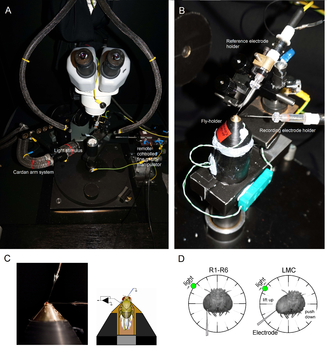
- 由两个鹅颈光导( 图6A)(与法拉第笼内部的冷光源)照射从上方飞制备平台磁极,使得飞保持器所用的优选的位置被放置在磁极附近的视觉控制下。

图6. 定位飞持有者和苍蝇保持器被放置在记录平台还通过珀耳帖元件(A:白色圆形平台在中心)提供的温度控制在电极上的实验(AB)。万向臂能够以相等的距离(通过的x,y旋转)周围的飞光刺激的准确定位,与光源(液体或石英光纤束端)直接指向它的眼睛。在许多的OUř钻机,由LED产生的光刺激(线性电流驱动器)或通过单色仪。因此,他们随身携带的刺激特定的(带通信)频谱内容,300之间选择 - 740 nm和覆盖4 - 6日志强度单位范围(由独立的中性密度滤光片作为衰减)。 (C)的两个微电极,由单独显微控制,被定位在飞头:参考电极(段)通过单眼;记录电极(左)通过在左眼的小开口。 (D)为取得感光体记录的最大数目时,记录微电极被驱动到孔,平行于长鼻-单眼轴。当电极尖端贯通和密封,以感光体,自由旋转光源被固定到那里的细胞产生给定的光刺激的最大电压响应的位置。这点在空间在于细胞的感受野的中心。如果孔我收盘角质层,渗透LMC可以进一步与此相同的电极角度(左)来实现的。如果孔从角质层进一步,另一个有用的电极接近角获得LMC记录也显示(右图)。 请点击此处查看该图的放大版本。
- 安装飞持有人(在它飞!)在飞行中试平台极。旋转蝇保持器,使得蝇左眼直接面对研究者( 图6B)。
- 通过蝇occelli成使用小粗显微同时观察通过立体显微镜( 图6C)的制备头壳轻轻插入钝参考电极。不要推电极太深,否则会损坏苍蝇大脑。
- 可替代地,插入参比电极到胸部的后面。始终,确保飞行出现希西(移动触角),它的眼睛是完整的;不小心损坏。如果准备看起来不到完美无暇的,准备实验新飞。
- 驱动锐记录微电极进入过凡士林的左眼覆盖提前准备的小口。使用高倍率的立体和移动的光导和焦平面从而使电极尖端位置由它的反射模式在3D变得明显。
注意: 图6D显示了飞的头应该略有不同地定位(在相对 于记录微电极进入眼睛的角度)为感光体和LMC的录音。驱动电极到眼睛中不破坏它是在实验的最困难的阶段。如果电极尖端射门在眼的小开口,击中角膜,它典型地断裂。 - 打开微电极放大器一旦这两个电极牢固地制备内,在与飞的体液的电接触。
- 关闭冷光源(法拉第笼子里)以及电源拔掉它。它的插头连接到中央接地,以尽量减少接地回路引起的电气噪音,以及移动鹅颈光导走,使万向臂系统可以绕飞自由移动。关掉房间的灯,以确保飞准备现在处于相对的黑暗。
- 测量在眼睛(按照指示在放大器的用户手册)记录电极的电阻。仅使用记录电极,其中电阻为100 - 250MΩ。
注意:这几乎是不可能的<70MΩ电极来实现高品质的细胞内记录。如果电阻<80兆欧,它很可能是电极头被破坏。在这种情况下,关闭所述放大器和改变记录电极。- 一旦电极被替换,在眼睛,打开功放来测量其电阻。有时,电极头会被阻塞通过一些碎屑在进入组织。这可以通过使用放大器的电容嗡嗡声和电流脉冲函数来补救,通常明确它由快速谐振或排斥。
- 功放设置为电流钳(CC)或桥接录制模式。抵消在记录和参考电极之间的任意电压差,因为两者都现在搁在电互连细胞外的空间,由信号偏移(记录电压)设置为零。按照使用放大器的显示读数或示波器屏幕上的信号偏移变化。
- 等待复眼2-3分钟的暗适应。
- 驱动记录电极尖端逐渐更深地进入眼小0.1至1微米的步骤。与远程控制的微操作或b的x轴压电步进要这样做Ÿ轻轻转动手动机械手的精细分辨率旋钮。
- 刺激短暂复眼(1 - 10毫秒)灯闪烁作为记录电极在组织正在推进。
注意:如果在记录电极被定位在视网膜和眼睛的功能正常,每个光闪光会引起电压的简要和小滴(0.2 - 5毫伏超极化),称为电图(ERG)。在细胞外空间的场电位这种变化是由视网膜细胞'对光集体反应引起的。然而,一旦在电极尖端进入薄层,关闭上低收入国家,ERG的反转,表示去极化响应。 - 通过使用万向接头形臂系统走动复眼光源和找到在光唤起最大ERG响应的位置。
注意:此位置在视觉空间标记的小区域,其中光感受器(或低收入国家),其毗邻于记录电极的端部,品尝他们的光输入。 - 穿透与记录电极的细胞。
注:可以自发进行的渗透,或当电极是微上前。它可以通过轻轻敲击显微系统或者通过使用放大器的嗡嗡声功能进一步简化;这些动作共鸣在组织中的电极末端。当电极刺穿感光膜,在进入细胞内空间中,记录和参考电极之间的电压差下降突然从0 mV至〜-65毫伏(-55和-75毫伏之间);而在LMC渗透,这种下降通常是以下(-30和-50毫伏之间)。这些电压差代表在给定的细胞的负静息电位。根据记录电极(其锐度)和细胞过程它侵入的质量,从记录电极的电压读数能迅速或逐渐稳定至静息电位,作为细胞膜密封到电极的外层。但是,如果渗透仅是局部或差,电极通常滑出与记录的潜在攀登背面朝向零的细胞。 - 本地化侵入细胞的感受野的中心时,电极出现适当密封,显示出稳定的膜电位(暗静止电位)。移动闪烁光刺激周围的复眼,采用万向臂系统,发现在视觉空间,那里的灯闪唤起电池的最大电压响应的地步。锁定卡丹臂当光刺激直接面对(点)的感受野中心。
注:在黑暗中, 果蝇光感受器明亮的光脉冲响应与40 - 65 mV的去极化电压响应4,5,而稳定的LMC唱片展20〜45 mV的超极化9,10的反应。神经胶质细胞渗透可能很少发生,通过<-80 mV的静息电位和慢得多指示和较小的(〜5毫伏)饱和光诱导的去极化。在果蝇光感受器具有不同的眼睛色素沉着,如白眼球7和朱砂,展现媲美响应大小,以野生型。 - ( - 200毫秒100)的电流脉冲进入研究细胞细胞膜充电过程中,尽量减少记录文物使用放大器的电流钳(CC)模式,通过注入小0.1 nA和简要补偿记录电极的电容。
注意:此重要程序是在放大器的用户手册详细地解释,并应与实际实验之前的电小区模型的情况下实施。 - 记录电压响应光脉冲和其他感兴趣的刺激,具有不同的统计或物理性质(如自然光强度的时间序列或随机对比图案)。试验中,例如,所记录的回答与光或暗适应如何变化。
注意:一,可以准确地里由光路4,5上加入中性密度滤光片GHT-适应由连续光预选强度的研究细胞。可替代地,对于延长的暗适应关掉光刺激预设时间。因为记录系统的机械稳定性,记录电极的高品质和制剂的完整性,稳定的记录条件有时可以持续许多小时。因此,在一个很好的一天,有可能在从一个单一的细胞不同适配条件来收集大量的数据。当电极滑出细胞,记录的响应降低,平均电压开始接近零。 - 直到电极进行接触并穿透下细胞小心前进与显微的微细x轴控制记录电极(这通常是最近的神经邻居)。不沿y轴或z轴移动至电极作为这些机动将使电极为"复ough组织"当中,破坏眼的结构!
注意:对于一个好的电极和健康的制剂,可以从许多光感受器(来自许多低收入国家但很少)在经过一段数小时同一飞行记录高质量的反应;偶尔,在整个工作日(> 8小时)没有明确的信号恶化。 - 保存的数据文件周期性地标识信息,如日期,基因型,并且所记录的细胞类型。由于大量可以在一个成功的记录会话收集的数据中,保持良好的书面记录在实验室书为未来的数据分析。
结果
锋利微电极记录方法中,作为此处适于果蝇眼睛,可以用于可靠地量化它们4,5,7,8,10,33之间在视网膜和薄层细胞神经信息采样和处理,以及通信。通过使用它来研究不同的野生型股票,突变或基因工程菌蝇编码,该方法已证明了其价值;不仅在量化的突变,温度,饮食或选定表达3,4,6,9,10,14,30,34的影响,而且也揭示了改变的视觉行为14,34机械的原因。该方法也容易适用于其他昆虫的准备工作35,36,赋予神经行为学研究的视野。接下来,我们展示的其成功的应用的几个例子。

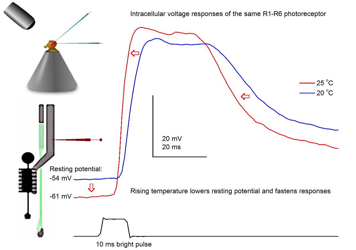
图7. 电压一个果蝇R1-R6感光的反应,在20的光脉冲和25℃。由于尖锐的微电极穿透通常非常稳定,所以可以在同一R1-R6感光体电压响应在记录到一个给定的光刺激不同的环境温度下通过加热或冷却该飞。在我们的调校,蝇保持器被置于一个闭环基于珀尔帖元件的温度控制系统。这使我们能够改变飞的头温度为秒。较高的温度加速电压响应和典型降低R1-R6光感受器的静息电位(用红色箭头所示)。 请点击此处查看该图的放大版本。
研究温度对感光输出的影响
使用一个精心设计和振动隔离的记录系统中,可用于通过变暖测量温度对单个细胞的神经元的输出的影响或冷却飞方法。给出的例子展示了一个明亮的10毫秒长脉冲,在20和25℃( 图7)记录在同一个R1-R6感光电压响应。由于4,9之前量化,气候变暖降低黑暗感光的静息电位,并加速其电压响应。

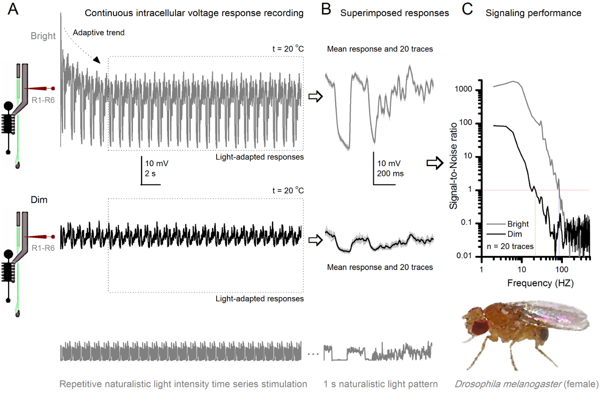
图8. 信令性能果蝇R1-R6感光随光照强度提高 (A)感光输出变暗(下图)和光明(以上; 10,000次亮的光)通过重复同样的微电极记录的自然光强度的时间序列在20℃。在同一小区回应明亮的刺激较大,因为它们集成更多的样本,基本反应(碰撞),单光子4,5,7,8。 (B)连续20个一秒长的电压响应叠加。个体反应(浅灰色)后的自适应趋势采取(以A箭头)已消退(在一个虚线框)。相应的响应的装置(的信号)是较暗的痕迹。信号和单独的响应之间的差异是噪声。 (C)将细胞使用标准方法4,5,7,8信号-噪声比(SNR)的'信令性能通过录音量化"。感光体输出具有在明亮的刺激"比在昏暗的( 明亮 ≥1,高达84赫兹(SNR约64赫兹范围更广可靠的信令的SNR)," 昏暗 ≥1,高达20赫兹),其中signal-信噪比改善大大;从SNR 昏暗 MAX = 87 SNR 亮 MAX = 1868。 请点击此处查看该图的放大版本。
通过反复刺激学习适应和神经编码
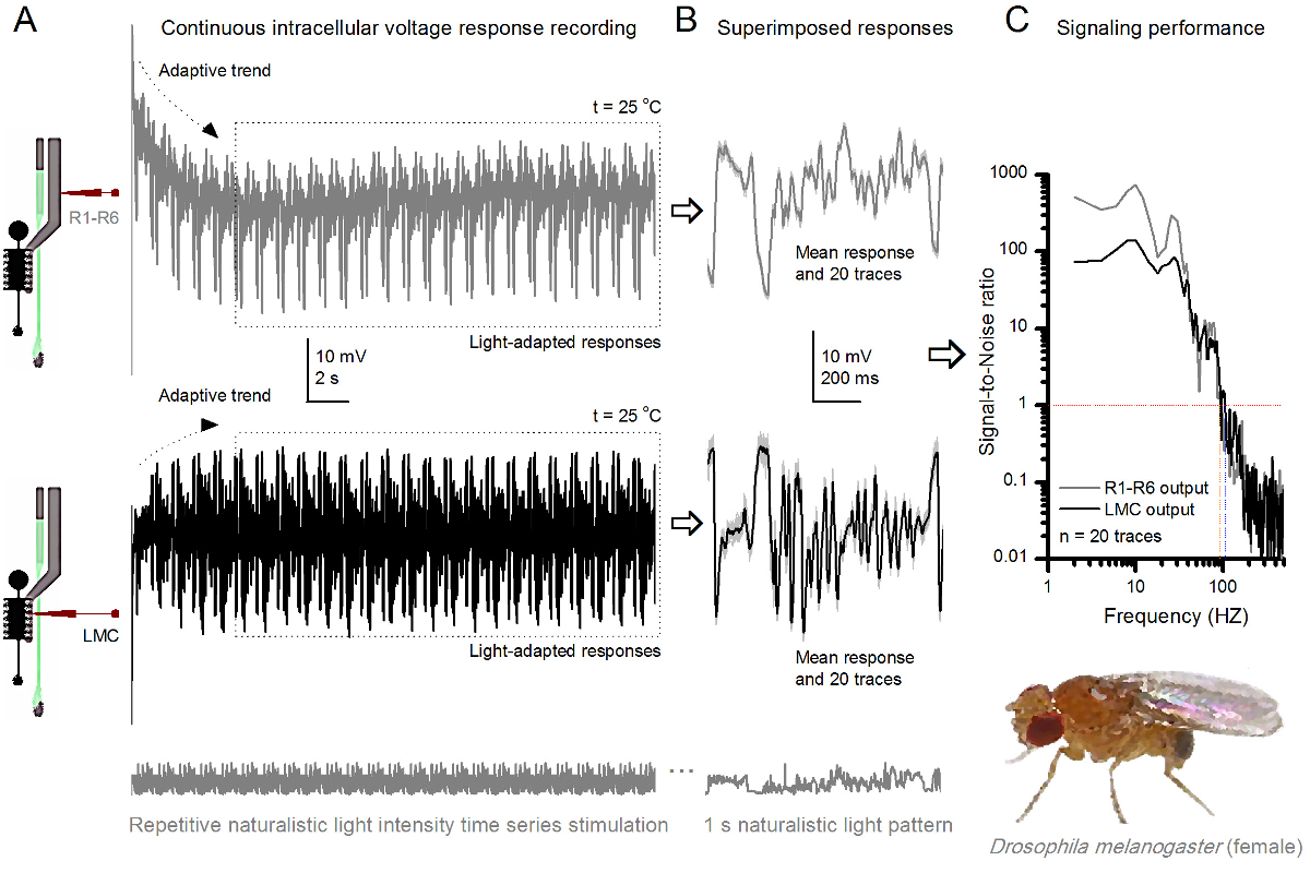
的方法中,使在视网膜和薄层结构相对较少损害的无创性,使得它非常适合研究各个细胞在体内其邻近自然生理状态不同的光刺激的信令性能。 图8示出R1-的电压响应R6光感受器昏暗和明亮的反复自然光强度的时间序列刺激在20℃,而图9 的信息显示,在25 摄氏度的另一个R1-R6光感受器和LMC到不同的自然刺激的反应前和突触后录音被因为同时细胞内记录在同一飞两头尖微电极,一个在视网膜和其它在椎板,太难可行30从两个不同的苍蝇分开执行。

要反复刺激自然主义在25 摄氏度 (A)R1-R6(灰色)和LMC(黑色) 果蝇R1-R6光感受器和LMC 图 9. 电压输出的响应由来自不同苍蝇不同的微电极记录下来。 (B)全光适应连续20前(上图),并与个体反应一样自然的刺激模式突触后(下)的反应,在光显示灰色的D中的相应的响应的装置(的信号)作为暗痕迹。信号和单独的响应之间的差异是噪声。 (C)的细胞信号-噪声比(SNR)的'信令性能通过录音量化"。 LMC输出具有"比R1-R6输出(SNR(LMC≥1,高达104赫兹- [R≥1,高达94赫兹)约10赫兹范围更广的可靠信号的信噪比 )"。这两个信号与噪声的比值高(SNR LMC MAX = 142, 信噪比读取 最大 = 752),并作为记录噪音低,他们之间的分歧反映了细胞之间的真正的编码区别。 请点击此处查看大图这个数字。
刺激发病后,录音典型LY秀快适应了5-6秒内消退主要趋势。从那时起,在细胞产生的每个1秒长刺激呈现(各虚线框包围的这些20)高度一致的反应。当这些叠加( 图8B和图9B)的响应的可重复性变得明显。个体反应是细灰的痕迹,他们的意思是较厚的深色痕迹。平均响应被作为神经信号 ,而神经噪声的平均值和每个单独的响应4,5,9,37,38之间的差。在频域中的相应的信号对噪声比( 图8C和图9C)被傅立叶变换的信号和噪声的数据块到功率谱,并除以对应的平均噪声功率谱4的平均信号功率谱得到5,9,37,38。特征,最大信号 - 噪声比öF中的记录,神经输出到自然的刺激是高(100 - 1000),并且在具有非常低记录噪声最稳定的制剂可达到的值>> 1000( 例如 , 图8C)。还要注意的是气候变暖扩大了细胞的信号的可靠带宽4(SNR' 光明 ≥1);例如,在图8 和9两R1-R6S之间的相对差,分别是10赫兹(84在20℃,并在25℃下94赫兹)。
一个可以通过使用香农公式32,或通过三重外推法39计算的响应"熵和噪声熵率之间的差进一步估计距其信噪比信息传输的每个细胞的速率。有关信息理论分析的更多细节,以及它们的使用和限制š专门用这种方法在以前的出版物7,8,39中给出。

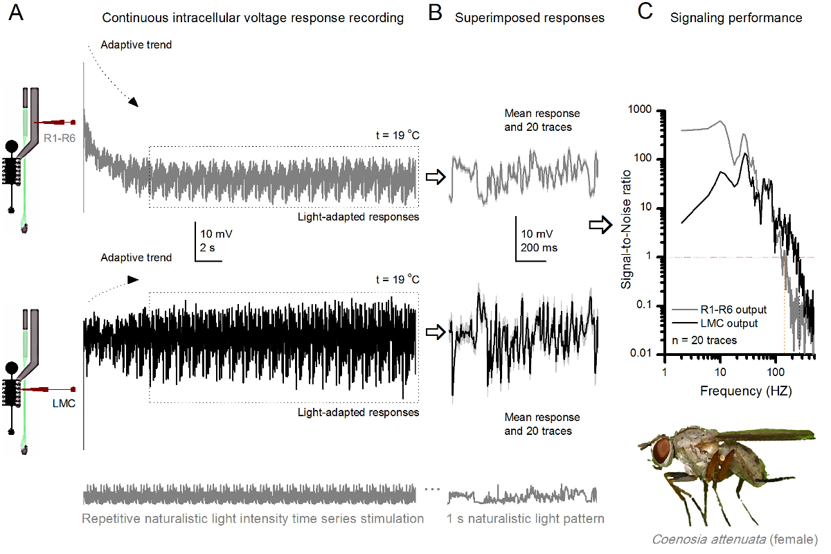
杀手粉煤灰,R1-R6光感受器和LMC的 图10 的电压响应反复自然主义刺激在19℃。(A)中,R1-R6(灰色)和LMC(黑色)输出从同一飞同一微电极记录;第一突触后和突触前后,作为电极是在眼推进。 (B)连续20前(上)和突触后(下)的反应(浅灰色的痕迹),以同样的自然刺激模式进行了初步适应(在一个虚线框)后抓获。他们的手段是信号(在顶部的暗的痕迹),而他们各自的个体反应的差异给出的噪音。 (C)的相应的Signa1对噪声比(SNR),计算为在图8C和9C所示 。 LMC输出有关于"比R1-R6输出(LMC MAX≥1,高达234赫兹(SNR 100赫兹范围更广的可靠信号的信噪比 )'R MAX≥1,最高134赫兹)。两个信号-噪声比是高信噪比(SNR LMC MAX = 137, 信噪比读取 最大 = 627),并作为同一微电极是在录音使用时,它们的差异反映了前和突触后神经输出的实际差别。这些结果表明,该系统记录了低噪音,及其对分析的影响是微不足道的。 请点击此处查看该图的放大版本。
神经行为学研究视野
该方法也可以用来从不同的昆虫物种7,8,35,36的复眼( 图10)记录前和突触后电压响应,允许可视信息处理的比较神经行为学研究。对于所提出的记录系统中,唯一需要的适应是新制备持,各与用于研究的物种适宜尺寸的开口。这些示范录音是从女杀手飞( 秽蝇attenuata)的。它们表现出R1〜R6感光体和LMC到相同的重复光刺激的细胞内电压响应,作为用于果蝇对应于图9中 ,但在19℃。在这种情况下,无论是前和突触后的数据是从同一飞行记录;一前一后,用同样的记录电极(填充用3M KCl)中通过侧面薄层第一前进之前进入ING额视网膜。在25℃时, 秽蝇数据相比于果蝇数据-即使在冷却器温度-示出了具有更快的动力学响应;扩大可靠的信令(信噪比>> 1)在较宽的频率范围内的范围。在自然刺激神经 编码这种功能的修改与秽蝇的掠夺性生活36,这需要高精度的时空信息,以实现快速的空中狩猎行为是一致的。
讨论
We have presented the basic key steps of how to use sharp conventional microelectrodes to record intracellular responses of R1-R6 photoreceptors and LMCs in intact fly eyes. This method has been optimized, together with bespoke hardware and software tools, over the last 18 years to provide high-quality long-lasting recordings to answer a wide range of experimental questions. By investing time and resources to construct robust and precise experimental set-ups, and to produce microelectrodes with favorable electrical properties, high-quality recordings can become the norm in any laboratory working on Drosophila visual neurophysiology. Whilst well-designed recording and light stimulation systems are important for swift execution of different experimental paradigms, there are three procedural steps that are even more critical to achieving successful recordings: (i) to make the fly preparation with minimal eye damage, (ii) to pull microelectrodes with the right electrical properties, and (iii) to drive the recording electrode into the eye without breaking its tip. Ultimately, to record meaningful data, the investigator has to understand the physical basis of electrophysiology and how to fabricate suitable microelectrodes for the targeted cell-types.
Therefore, the limitations of this technique are primarily set by the patience, experience and technical ability of the investigator. Because this technique can take a long time to master for small Drosophila cells, it is advisable for trainee electrophysiologists to first practice with larger insect eyes, such as the blowfly36 or locust35, using the same rig. Once performing high-quality intracellular recordings from the larger photoreceptors and interneurons becomes routine, it is time to move on to the Drosophila eye. Another limitation of the technique concerns cellular identification. Penetrated Drosophila cells can be loaded electrophoretically with dyes, including Lucifer yellow or neurobiotin. However, because of the small tip size of the microelectrodes, electrophoresis works less efficiently than with lower resistance electrodes, such as patch-electrodes. Furthermore, the dye-filled microelectrodes characteristically have less favorable electrical properties, making it much harder to record high-quality responses with them from Drosophila photoreceptors and LMCs.
A technical problem that occurs sometimes is unstable input signal, or a complete lack of it. This is often associated with the voltage signal being either constantly drifting or higher/lower than the amplifier's recording range. On most occasions, this behavior is caused by the recording electrode being blocked (or its tip being too fine - having too high a resistance or intramural capacitance - to properly conduct fast signal changes). Although one can try to unblock the tip by buzzing the electrode capacitance, which sometimes works, often the situation is best resolved by simply changing the recording electrode. This may further require parameter adjustments in the microelectrode puller instrument to lower the tip resistance of the new electrodes. The electrode tip can also become blocked in preparations, for which it took too much time to cover the corneal hole by petroleum jelly. Prolonged air-contact can dry up the freshly exposed retinal tissue, turning its surface layer into a glue-like substance. If this is the case, the investigator typically sees a red blob of tissue stuck on the recording electrode when pulling it out of the eye. The only solution here is to make a new preparation. Petroleum jelly may provide many benefits for electrophysiological recordings: (i) it prevents the coagulation of the hemolymph that could break the electrode tip; (ii) it coats the electrode tip reducing its intramural capacitance, which lowers the electrode's time constant, and thus has the potential to improve the temporal resolution of the recorded neural signals40,41; (iii) it keeps the electrode tip clean, facilitating penetrations; and after penetration, (iv) it may even help to seal the electrode tip to the cell membrane42.
The signal can further be unstable or lost when the silver-chloride wire of the electrode-holder is broken or dechloridized; in which case just replace or rechloridize the old wire. The missing signal can also result from one (or both) of the electrode-holders not being securely connected to their jacks. However, it is extremely unusual that a piece of equipment would be malfunctioning. If signal is undetectable and all other possibilities have been exhausted, test that each part of the recording apparatus, including the headstage, amplifier, low-pass filters and AD/DA-converters, are connected properly and functioning normally. One way to achieve this is to replace each instrument with another from a rig that is known to operate normally. Alternatively, use a signal generator to check the performance of the electronic components one by one.
But perhaps the most common technical problem facing the electrophysiologist is that of recording noise. Broadly, recording noise is the observed electrical activity other than the direct neuronal response to a given stimulus. Because the fly preparation, when properly done, is very stable, the observed noise (beyond the natural variably of the responses) most often results from ground-loops in the recording equipment, or is picked up from nearby electrical devices. Such noise is typically 50/60 Hz mains hum and its harmonics; but sometimes composed of more complex waveforms. To work out the origin of the noise, remove the fly preparation holder from the set-up, connect the recording and reference electrodes through a drop of fly Ringer (or place them in a small Ringer's solution bath; see step 1.2.6) and record the signal in CC- or bridge-mode. If noise is observable on the recorded signal, this likely means that the noise is external to the fly preparation.
Another good test for identifying the origin of noise is to replace the electrode-holders with an electric cell model connected to the amplifier. In an ideally configured and grounded set-up, the recorded signal should now be practically noise-free, showing only stochastic bit-noise from the AD-converter (in the best case not even that!). If noise is still present, then recheck that all rig equipment is properly grounded. A convenient approach to detect ground-loops is to: (i) disconnect all the grounding wires from all the parts within the rig; (ii) ensure that, after doing this, every single part is actually isolated from ground, by means of an ohm-meter; (iii) connect the parts, one by one, to the central ground directly, not through any other part of the rig. Try also changing the equipment configurations. For example, sometimes moving the computer and monitor further away from the rig can reduce noise; yet at other times, moving the computer inside the equipment rack reduces noise. It is also worth unplugging nearby equipment to see if noise is reduced, or shield additional components. Furthermore, try unplugging or replacing different components of the recording equipment, especially BNC cables (which can have faulty ground connections). If only bit-noise is observed when using the cell model, the initial noise source is either the electrodes or the fly preparation itself. For example, it could be that the reference electrode is inadvertently touching a motor nerve or active muscle fibers inside the head capsule (or disturbing flight muscles in the thorax - if placed there). It is usually simplest to prepare a new fly for recording, taking care to minimize damage to the fly. But if the noise persists and is broadband, it is likely that the electrodes are suboptimal for the experiments; too sharp/fine (hence too noisy) or just wrong for the purpose; we have even seen quartz-electrodes acting as antennas - picking up faint broadcasting signals! Although iteration of the puller-instrument parameter settings to generate the just right microelectrodes for consistent high-quality recordings from specific cell-types can take a lot of effort, it is worth it. Once the recording electrodes are well-tailored for the experiments, they can provide long-lasting recordings of outstanding quality.
Sharp microelectrode recording techniques can be similarly applied to study neural information processing in multitude of preparations, including different processing layers in the insect eyes and brain43,44. Because the microelectrode tips can be made very fine, these typically damage the studied cells less than most patch-clamp applications. Importantly, the modern sample-and-hold microelectrode amplifiers enable good control of the tips' electrical properties40,45-47. Thus, when correctly applied, this technique can provide reliable data from both in vivo3,5,7-10,44 or in vitro48 preparations with high signal-to-noise ratio at sub-millisecond resolution. Such precision would be impossible with today's optical imaging techniques, which are noisier and slower. Moreover, the method can be used to characterize small cells' electrical membrane properties both in current- and voltage-clamp configurations5,29,33,36,40-42,49, providing valuable data for biophysical and empirical modeling approaches7,8,11,33,49-54 that link experiments to theory.
披露声明
The authors have nothing to disclose
致谢
The authors thank Mick Swann, Chris Askham and Martin Gautrey for their important contributions in designing and building many electrical and mechanical components of the rigs. MJ's current research is supported by the Biotechnology and Biological Sciences Research Council (BBSRC Grant: BB/M009564/1), the State Key Laboratory of Cognitive Neuroscience and Learning open research fund (China), High-End Foreign Expert Grant (China), Jane and Aatos Erkko Foundation Fellowship (Finland), and the Leverhulme Trust grant (RPG-2012-567).
材料
| Name | Company | Catalog Number | Comments |
| Stereo Zoom Microscope for making the fly preparation | Olympus | SZX12 DFPLFL1.6x PF eyepieces: WHN30x-H/22 | Capable of ~150X magnification with long working distance; bespoke heavy steel table mount stand |
| Stereomicroscope in the intracellular set-up | · Olympus | Olympus SZX7; eyepieces: WHN30x-H/22 | 30X eyepieces are needed for seeing the electrode tip reflections well when driving it through the small corneal hole into the eye |
| Nikon microscope | Nikon SMZ645; eyepieces: C-W30x/7 | ||
| Anti-vibration Table | Melles Griot | With metric M6 holes on the breadboard | Our bespoke rigs have a large hole drilled through the thick breadboard that lets in the fly preparation platform pole (houses a copper heatsink with electronics) from below |
| Newport | |||
| Micromanipulators | Narishige | Narishige NMN-21 | In our intracellular set-ups, different micromanipulator systems are used for driving the shap recording electrodes into the fly eye. All the listed manipulators are succesfully providing long-lasting stable recordings from Drosophila photoreceptors and LMCs. |
| Huxley Bertram | Huxley xyz-axis with fine manual control | ||
| Sensapex | Sensapex triple axis | ||
| Märzhäuser | Märzhäuser DC-3K with additional x-axis piezo stepper and MS 314 controller | ||
| Magnetic Stands | Any magnetic base with on/off switch will do | For example, to manage cables inside the Faraday cage | |
| Electrode Holders | Harvard Apparatus | ESP/W-F10N | |
| Silver Wire | World Precision Instruments | AGW1510 | 0.3 - 0.5 mm diameter; needs to be chloridized for the electrode holders |
| Fiber Optic Light Source | Many different, including Olympus | ||
| Fiber Optic Bundles | UltraFine Technology | To deliver the LED light stimulus to the Cardan arm system. We use both liquid and quartz light guides (range from UV to IR) | |
| Thorn Labs | |||
| Fly Cathing Tube | P80-50P 50ml Cent. Tube PP., Pack of 100 Pcs | Cut the conical bottom off from 50 ml Plastic Centrifuge Tube and glue a 1 ml pipette tip on it. | |
| Digital Acquisition System | National Instruments | ||
| Single-electrode current/voltage-clamp microelectrode amplifier | npi SEC-10LX | http://www.npielectronic.de/products/amplifiers/sec-single-electrode-clamp/sec-10lx.html | Outstanding performer! |
| Head-stage | Standard (+/- 150 nA) | For npi SEC-10LX | |
| LED light sources and drivers | 2-channel OptoLED (Cairn Research Ltd., UK) | Many of our stimulus systems are in-house built | |
| Self-designed and constructed | |||
| Acquisition and Analyses Software | Many companies to choose from | Biosyst; custom written Matlab-based system for experimental and theoretical work in the Juusola laboratory | |
| Personal Computer or Mac | Ensure that PC or Mac is compatible with data acquisition system and software | ||
| Cardan arm system | Self-designed and constructed | Providing accurate x,y,z-positioning of the light stimuli | |
| Peltier temperature control system | Self-designed and constructed | ||
| Faraday Cage | Self-constructed | Electromagnetic noise shielding | |
| Filamented Borosilicate Glass Capillaries | Outer diameter: 1 mm | ||
| Inner diameter: 0.5 - 0.7 mm | |||
| Filamented Quartz Glass Capillaries | Outer diameter: 1 mm | ||
| Inner diameter: 0.5 - 0.7 mm | |||
| Pipette Puller | Sutter Instrument Company | Model P-2000 laser Flaming/Brown Micropipette Puller | For borosilicate reference electrodes, use the preset program #11 (patch electrodes): Heat = 350; Filament = 4; Velocity 36; Delay = 200).1.2.1). For borosilicate recording electrodes, use the preset program #12 (this typically pulls good conventional sharps for photoreceptor recordings): Heat = 355; Filament = 4; Velocity 50; Delay = 225; Pull = 150. For LMC recordings, which require electrodes with finer tips, these values need to be adjusted. For pulling quartz capillaries, P-2000 manual suggests programs for fine tipped microelectrodes. These programs’ preset parameters serve as useful starting points for systematic modifications to generate electrodes with good penetration success and low recording noise. |
| Extracellular Ringer Solution for the reference electrode | Chemicals from Fisher Scientific | 10326390, NaCl 10010310, KCl 10147753, TES 10161800, CaCl2 10159872, MgCl2 10000430, sucrose | See the recipe in the protocol section |
| 3 M KCl solution for filling the filamented recording microelectrode | Salts from Fisher Scientific | 10010310, KCl | |
| Petroleum jelly | Vaselin | ||
| Non-stainless steel razor blades | |||
| Blade holder/breaker | Fine Science Tools By Dumont | 10053-09 | 9 cm |
| Blu-tack | Bostik | Alternatively, use molding clay | |
| Forceps | Fine Science Tools By Dumont | 11252-00 | #5SF (super-fine tips) |
参考文献
- Meinertzhagen, I. A., O'Neil, S. D. Synaptic Organization of Columnar Elements in the Lamina of the Wild-Type in Drosophila-Melanogaster. J Comp Neurol. 305, 232-263 (1991).
- Rivera-Alba, M., et al. Wiring Economy and Volume Exclusion Determine Neuronal Placement in the Drosophila Brain. Curr Biol. 21, 2000-2005 (2011).
- Abou Tayoun, A. N., et al. The Drosophila SK Channel (dSK) Contributes to Photoreceptor Performance by Mediating Sensitivity Control at the First Visual Network. J Neurosci. 31, 13897-13910 (2011).
- Juusola, M., Hardie, R. C. Light adaptation in Drosphila photoreceptors: II. Rising temperature increases the bandwidth of reliable signaling. J Gen Physiol. 117, 27-41 (2001).
- Juusola, M., Hardie, R. C. Light adaptation in Drosophila photoreceptors: I. Response dynamics and signaling efficiency at 25 degrees. C. J Gen Physiol. 117, 3-25 (2001).
- Pantazis, A., et al. Distinct roles for two histamine receptors (hclA and hclB) at the Drosophila photoreceptor synapse. J Neurosci. 28, 7250-7259 (2008).
- Song, Z., Juusola, M. Refractory sampling links efficiency and costs of sensory encoding to stimulus statistics. J Neurosci. 34, 7216-7237 (2014).
- Song, Z., et al. Stochastic, Adaptive Sampling of Information by Microvilli in Fly Photoreceptors. Curr Biol. 22, 1371-1380 (2012).
- Zheng, L., et al. Feedback network controls photoreceptor output at the layer of first visual synapses in Drosophila. J Gen Physiol. 127, 495-510 (2006).
- Zheng, L., et al. Network Adaptation Improves Temporal Representation of Naturalistic Stimuli in Drosophila Eye I Dynamics. Plos One. 4, (2009).
- Hardie, R. C., Juusola, M. Phototransduction in Drosophila. Curr opin neurobiol. 34, 37-45 (2015).
- Clandinin, T. R., Zipursky, S. L. Making connections in the fly visual system. Neuron. 35, 827-841 (2002).
- Wernet, M. F., et al. Homothorax switches function of Drosophila photoreceptors from color to polarized light sensors. Cell. 115, 267-279 (2003).
- Wardill, T. J., et al. Multiple Spectral Inputs Improve Motion Discrimination in the Drosophila Visual System. Science. 336, 925-931 (2012).
- Hardie, R. C. Progress in Sensory Physiology. Ottoson, D. 5, Springer. 1-79 (1985).
- Borst, A. Drosophila's View on Insect Vision. Curr Biol. 19, 36-47 (2009).
- Kirschfeld, K. Die Projektion Der Optischen Umwelt Auf Das Raster Der Rhabdomere Im Komplexauge Von Musca. Exp Brain Res. 3, 248-270 (1967).
- Morante, J., Desplan, C. Photoreceptor axons play hide and seek. Nat Neurosci. 8, 401-402 (2005).
- Fischbach, K. F., Hiesinger, P. R. Optic lobe development. Adv Exp Med Biol. 628, 115-136 (2008).
- Shaw, S. R. Early Visual Processing in Insects. J Exp Biol. 112, 225-251 (1984).
- Joesch, M., Schnell, B., Raghu, S. V., Reiff, D. F., Borst, A. ON and OFF pathways in Drosophila motion vision. Nature. 468, 300-304 (2010).
- Clark, D. A., Bursztyn, L., Horowitz, M. A., Schnitzer, M. J., Clandinin, T. R. Defining the Computational Structure of the Motion Detector in Drosophila. Neuron. 70, 1165-1177 (2011).
- Rister, J., et al. Dissection of the peripheral motion channel in the visual system of Drosophila melanogaster. Neuron. 56, 155-170 (2007).
- Vogt, N., Desplan, C. The first steps in Drosophila motion detection. Neuron. 56, 5-7 (2007).
- Strausfeld, N. J., Braitenberg, V. Compound Eye of Fly (Musca-Domestica) - Connections between Cartridges of Lamina Ganglionaris. Z Vergl Physiol. 70, 95-104 (1970).
- Strausfeld, N. J., Campos-Ortega, J. L4-Monopolar Neuron - Substrate for Lateral Interaction in Visual System of Fly Musca-Domestica (L). Brain Res. 59, 97-117 (1973).
- Takemura, S. Y., et al. Cholinergic Circuits Integrate Neighboring Visual Signals in a Drosophila Motion Detection Pathway. Curr Biol. 21, 2077-2084 (2011).
- Shaw, S. R., Frohlich, A., Meinertzhagen, I. A. Direct Connections between the R7/8 and R1-6 Photoreceptor Subsystems in the Dipteran Visual-System. Cell Tissue Res. 257, 295-302 (1989).
- Wolfram, V., Juusola, M. Impact of rearing conditions and short-term light exposure on signaling performance in Drosophila photoreceptors. J Neurophysiol. 92, 1918-1927 (2004).
- Nikolaev, A., et al. Network Adaptation Improves Temporal Representation of Naturalistic Stimuli in Drosophila Eye II Mechanisms. Plos One. 4, (2009).
- Land, M. F. Compound eye structure: Matching eye to environment. Adaptive Mechanisms in the Ecology of Vision. , Springer. Netherlands. (1999).
- Shannon, C. E. A Mathematical Theory of Communication. At&T Tech J. 27, 379-423 (1948).
- Niven, J. E., et al. The contribution of Shaker K+ channels to the information capacity of Drosophila photoreceptors. Nature. 421, 630-634 (2003).
- Randall, A. S., et al. Speed and sensitivity of phototransduction in Drosophila depend on degree of saturation of membrane phospholipids. J Neurosci. 35, 2731-2746 (2015).
- Faivre, O., Juusola, M. Visual Coding in Locust Photoreceptors. Plos One. 3, e2173(2008).
- Gonzalez-Bellido, P. T., Wardill, T. J., Juusola, M. Compound eyes and retinal information processing in miniature dipteran species match their specific ecological demands. P Natl Acad Sci USA. 108, 4224-4229 (2011).
- Juusola, M., Kouvalainen, E., Järvilehto, M., Weckström, M. Contrast Gain, Signal-to-Noise Ratio, and Linearity in Light-Adapted Blowfly Photoreceptors. J Gen Physiol. 104, 593-621 (1994).
- Juusola, M., Uusitalo, R. O., Weckstrom, M. Transfer of Graded Potentials at the Photoreceptor Interneuron Synapse. J Gen Physiol. 105, 117-148 (1995).
- Juusola, M., de Polavieja, G. G. The rate of information transfer of naturalistic stimulation by graded potentials. J Gen Physiol. 122, 191-206 (2003).
- Weckstrom, M., Kouvalainen, E., Juusola, M. Measurement of Cell Impedance in Frequency-Domain Using Discontinuous Current Clamp and White-Noise-Modulated Current Injection. Pflug Arch Eur J Phy. 421, 469-472 (1992).
- Juusola, M. Measuring Complex Admittance and Receptor Current by Single Electrode Voltage-Clamp. J Neurosci Meth. 53, 1-6 (1994).
- Juusola, M., Seyfarth, E. A., French, A. S. Rapid coating of glass-capillary microelectrodes for single-electrode voltage-clamp. J Neurosci Meth. 71, 199-204 (1997).
- Haag, J., Borst, A. Neural mechanism underlying complex receptive field properties of motion-sensitive interneurons. Nat Neurosci. 7, 628-634 (2004).
- Rien, D., Kern, R., Kurtz, R. Synaptic transmission of graded membrane potential changes and spikes between identified visual interneurons. Eur J Neurosci. 34, 705-716 (2011).
- Muller, A., et al. Switched single-electrode voltage-clamp amplifiers allow precise measurement of gap junction conductance. Am J Physiol-Cell Ph. 276, C980-C987 (1999).
- Polder, H. R., Swandulla, D., Konnerth, A., Lux, H. D. An Improved, High-Current Single Electrode Current Voltage Clamp System. Pflug Arch Eur J Phy. 402, R35-R35 (1984).
- Richter, D. W., Pierrefiche, O., Lalley, P. M., Polder, H. R. Voltage-clamp analysis of neurons within deep layers of the brain. J Neurosci Meth. 67, 121-131 (1996).
- Juusola, M., French, A. S. The efficiency of sensory information coding by mechanoreceptor neurons. Neuron. 18, 959-968 (1997).
- Vähäsöyrinki, M., Niven, J. E., Hardie, R. C., Weckström, M., Juusola, M. Robustness of neural coding in Drosophila photoreceptors in the absence of slow delayed rectifier K+ channels. J Neurosci. 26, 2652-2660 (2006).
- Friederich, U., Coca, D., Billings, S., Juusola, M. Data Modelling for Analysis of Adaptive Changes in Fly Photoreceptors. Lect Notes Comput Sc. 5863, 34-48 (2009).
- Asyali, M. H., Juusola, M. Use of Meixner functions in estimation of Volterra kernels of nonlinear systems with delay. Ieee T Bio-Med Eng. 52, 229-237 (2005).
- French, A. S., et al. The Dynamic Nonlinear Behavior of Fly Photoreceptors Evoked by a Wide-Range of Light Intensities. Biophys J. 65, 832-839 (1993).
- Juusola, M., French, A. S. Visual acuity for moving objects in first- and second-order neurons of the fly compound eye. J Neurophysiol. 77, 1487-1495 (1997).
- Juusola, M., Weckstrom, M., Uusitalo, R. O., Korenberg, M. J., French, A. S. Nonlinear models of the first synapse in the light-adapted fly retina. J Neurophysiol. 74, 2538-2547 (1995).
转载和许可
请求许可使用此 JoVE 文章的文本或图形
请求许可探索更多文章
This article has been published
Video Coming Soon
版权所属 © 2025 MyJoVE 公司版权所有,本公司不涉及任何医疗业务和医疗服务。