
Method Article
の記録細胞内の電圧応答のための電気生理学的手法
要約
Sharp microelectrodes enable accurate electrophysiological characterization of photoreceptor and visual interneuron output in living Drosophila. Here we show how to use this method to record high-quality voltage responses of individual cells to controlled light stimulation. This method is ideal for studying neural information processing in insect compound eyes.
要約
Voltage responses of insect photoreceptors and visual interneurons can be accurately recorded with conventional sharp microelectrodes. The method described here enables the investigator to measure long-lasting (from minutes to hours) high-quality intracellular responses from single Drosophila R1-R6 photoreceptors and Large Monopolar Cells (LMCs) to light stimuli. Because the recording system has low noise, it can be used to study variability among individual cells in the fly eye, and how their outputs reflect the physical properties of the visual environment. We outline all key steps in performing this technique. The basic steps in constructing an appropriate electrophysiology set-up for recording, such as design and selection of the experimental equipment are described. We also explain how to prepare for recording by making appropriate (sharp) recording and (blunt) reference electrodes. Details are given on how to fix an intact fly in a bespoke fly-holder, prepare a small window in its eye and insert a recording electrode through this hole with minimal damage. We explain how to localize the center of a cell's receptive field, dark- or light-adapt the studied cell, and to record its voltage responses to dynamic light stimuli. Finally, we describe the criteria for stable normal recordings, show characteristic high-quality voltage responses of individual cells to different light stimuli, and briefly define how to quantify their signaling performance. Many aspects of the method are technically challenging and require practice and patience to master. But once learned and optimized for the investigator's experimental objectives, it grants outstanding in vivo neurophysiological data.
概要
ミバエ( キイロショウジョウバエ )複眼は、神経画像サンプリングおよび処理のための感光体と介在ニューロンの配列の機能的な組織を調査するのに最適なモデルシステムであり、動物のビジョンのために。システムは、最も完全な配線図1,2を有しており、遺伝子操作および3-10(高い信号対雑音比と時間分解能の)正確な神経活動の監視に愛想です。
ショウジョウバエの目は一緒にその頭の周りのほぼすべての方向をカバーするパノラマ視野を飛ぶ提供個眼と呼ばれる〜750一見、通常のレンズキャップされた構造を含む、モジュール化されています。目の一次情報サンプリングユニットは、そのrhabdomeric光受容体7,8,11です。それぞれの個眼は、同じファセットレンズを共有する8光受容体細胞(R1-R8)を含むが、7つの異なる方向に整列されます。外光受容体R1-R6 ARながら青緑色の光、同じ方向に互いの上部と点に横たわる内側の細胞R7およびR8の分光感度、展示3独特のサブタイプに電子最も敏感:、淡い黄色と背側リムエリア(DRA)12- 15。

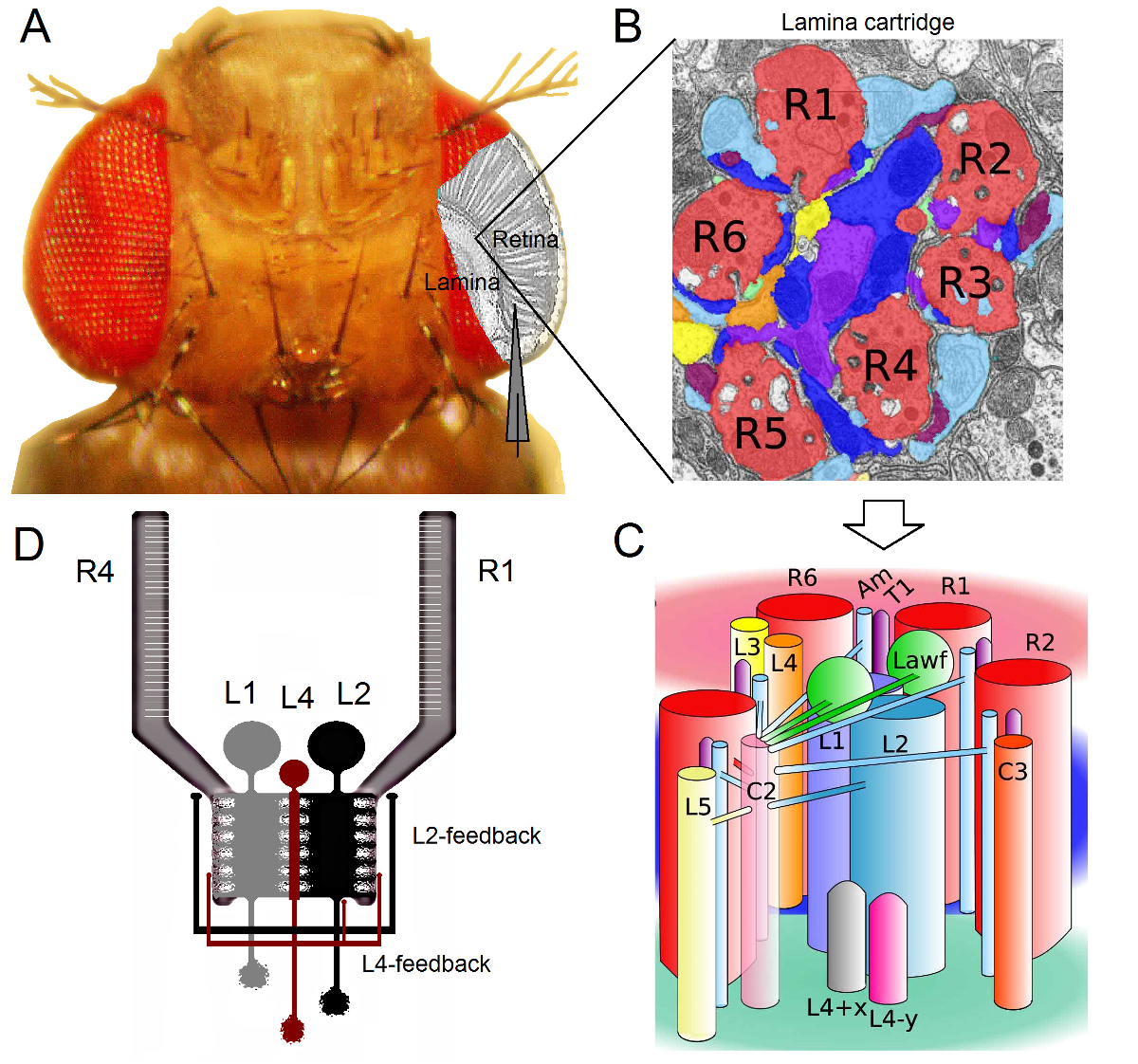
図1. ショウジョウバエ の目 の機能組織 。 (A)は、2つの第1の光学要素神経節、網膜およびラミナは、フライアイ内側の灰色で強調されています。網膜R1-R6の光受容体とラミナ大モノポーラ細胞(LMCS:L1-L3)は、従来の鋭い微小電極記録に生体内で容易にアクセスできます。模式電極は、網膜にR1-R6から記録するために通常のパスを強調しています。ラミナにLMCSから録音するための一つのパスを左に平行電極にシフトすることです。 (B)ラミナはretinotopically臓器のマトリックスであります視覚空間内の特定の小さな領域からの情報を処理するニューロンが詰め込まれて、それぞれが化さカートリッジ。神経重ね合わせのために、異なる隣接個眼から6の感光体は、L1〜L3とアマクリン細胞(アム)のヒスタミン出力シナプスを形成し、同じラミナカートリッジにその軸索(R1-R6)を送信します。ラミナカートリッジ内の(C)R1-R6の軸索末端と(L4、L5、Lawf、C2、C3とT1を含む)視覚介在ニューロン間の神経情報の普及は、複雑です。 (D)R1-R6の感光体の軸索は、L2とL4単極細胞からシナプスフィードバックを受けます。リベラ・アルバら2から変更された(B)及び(C)。 この図の拡大版をご覧になるにはこちらをクリックしてください。
ショウジョウバエの目は、神経重畳型16です。これは、トンを意味します帽子空間内の同じ点を見て7、隣接個眼に属する8の光受容体の神経信号は、次の2 neuropils内の1つの神経カートリッジで一緒にプールされていますラミナおよび髄質。 6外光受容体R1-R6プロジェクトラミナにおける神経の列への軸索の端末( 図1)が、R7およびR8細胞は、この層をバイパスし、それらに対応する髄質列17-19とのシナプス接触を行います。これらの正確な配線はすべてのラミナ( 図1A-C)その後、フライ初期視覚の網膜マッピングのための神経基盤を生成し、髄質カラム(カートリッジ)は、空間内の単一の点を表します。
ラミナ1,2,20およびアマクリン細胞(アム):R1-R6の光受容体からの直接入力が大型単極細胞(L1、L2とL3 LMCS)によって受信されます。これらのうち、L1、L2は、( 図1D)の主要な情報伝達経路を媒介する、WHIの最大の細胞でありますchのエッジをオンとオフの移動に応答し、したがって、動き検出器21,22の計算基礎を形成します。 L2細胞23,24におけるL1中にフロント、バックとフロントツーバック:行動実験は、中間対照的に、二つの経路が反対方向の運動知覚を促進することを示唆しています。接続は、さらにL4ニューロンは、隣接カートリッジ25,26間の横方向の通信において重要な役割を果たし得ることを意味します。逆数シナプスは、L2とL4同じに位置するセルと隣接する二つのカートリッジの間で発見されました。下流では、各L2細胞およびその関連する3つのL4細胞は、共通の目標に隣接カートリッジからの入力は、前面から背面への運動27の処理のために統合されると考えられている髄質、中Tm2がニューロンをその軸索を投射します。 L1のニューロンは、両方のギャップ結合とシナプスを介して、同じカートリッジL2Sからの入力を受け取るが、それらは直接L4sので、隣接するラミナカートリッジに接続されていません。
R1-R6の感光体の軸索へのシナプスのフィードバックは、L2 / L4回路に属するニューロンによってのみ提供されていなく、L1経路1,2( 図1D)。同じカートリッジの接続は、L2からR1とR2およびL4からR5に選択されている一方で、すべてのR1-R6の光受容体は、いずれかのL4または両方の隣接カートリッジからシナプスフィードバックを受けます。また、R1、R2、R4及びR5の時から強いシナプス結合が存在し、およびグリア細胞は、シナプスネットワークに接続され、従って、神経画像処理6に参加することができます。最後に、薄層に隣接したR1-R6をリンクし、R6およびR7 / R8光受容体との間に、ギャップジャンクション軸索は、各カートリッジ14,20,28における非対称情報の表現と処理に貢献しています。ほぼ無傷のショウジョウバエの個々の光受容体と視覚介在ニューロンからの細胞内の電圧の記録は高い信号対雑音Rを提供します接続されたニューロン間の高速神経計算の意味を理解するために必要なサブミリ秒の分解能3,5,7-10,29、のデータatio。 100ミリ秒の解像度 - 高精度のこのレベルは、有意に騒々しいであり、典型的には10で動作する現在の光イメージング技術によっては不可能です。電極は非常に小さく、鋭い先端を有するのでさらに、方法は、細胞体に限定されるものではないが、小さなアクティブ神経構造からの直接録音を提供することができます。このようなパッチクランプ電極のはるかに大きなヒントがアクセスすることはできませんLMCS「樹状突起や感光体の軸索、など。重要なことは、この方法は、ほとんどのパッチクランプのアプリケーションよりも構造的に低侵襲性および損傷であるので、あまり研究され、細胞の細胞内環境と情報のサンプリングに影響を与えます。このように、従来の鋭い微小電極技術が貢献し、かつ神経フォアに寄与し、基本的な発見やオリジナルの洞察に維持しています適切な時間スケールでの報処理;ビジョン3-10の我々のメカニズムの理解を向上させることができます。
この記事では、ショウジョウバエ R1-R6の光受容体とLMCSからin vivoでの細胞内記録はJuusolaの実験室で行われている方法について説明します。このプロトコルは、適切な電気生理学リグを構築する方法について説明フライを準備し、録音を行います。いくつかの代表的なデータが提示され、いくつかの一般的な問題や潜在的な解決策は、この方法を使用するときに遭遇する可能性があるという議論されています。
プロトコル
以下のプロトコルは、シェフィールド大学と北京師範大学の全ての動物保護ガイドラインに準拠しています。
1.試薬および器具の準備
- 記録と光刺激機器のセットアップ
- 規制湿度の空調を有しており、暗い記録条件を提供するために、意味の部屋で電気生理学的実験を行うために、少なくとも2.5×2.5メートルの記録領域を選択してください。すべてで囲まれ、リグは、2つのガチョウの首で、実体顕微鏡および冷光源[刺激と記録装置を飛ぶ]収容(ⅰ)1×1メートル振動絶縁表:このエリアは快適にフィットするのに十分な大きさであることを確認してください大> 180センチメートル背の高いファラデーケージ。 (ⅱ)を収容するための38Uのラックフラット液晶モニター、微小電極アンプ、LEDドライバ、フィルタ、温度制御ユニット、オシロスコープやその他の必要な電気機器を備えたパーソナルコンピュータ。および(iii)A小さな机や研究者のための椅子。
- このような冷蔵庫、遠心分離機やエレベーターのように、遠く離れた電気的、機械的ノイズ源からリグを置きます。主に発生する電圧スパイクからリグの電気機器を保護するために、個別のサージプロテクタを使用してください。理想的には、ノイズを最小限にするために、独自の無停電電源装置(UPSのバッテリ)にリグを接続します。
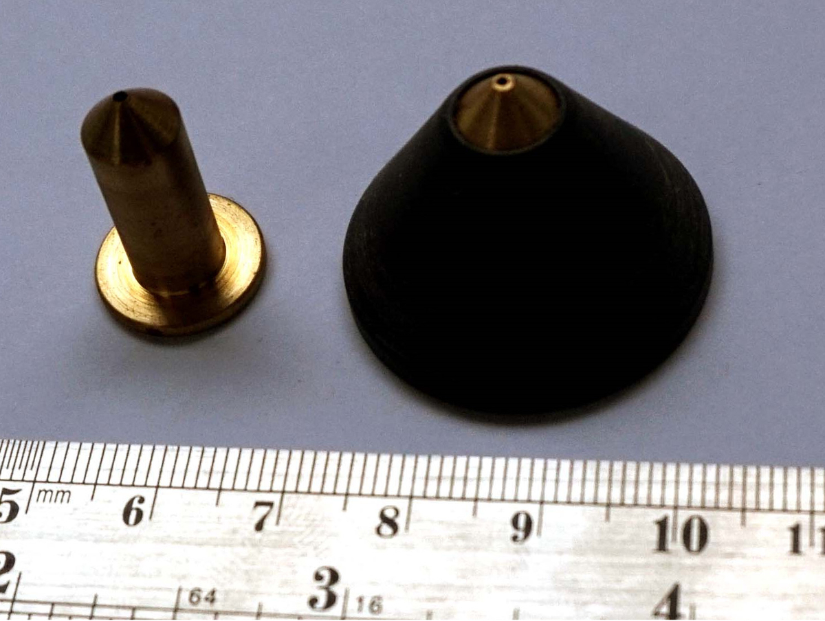
- 真鍮と黒のプラスチック( 図2)のうち、円錐形のフライホルダーを構築します。その外部リム狭小化へ〜(典型的なハエの胸部幅と一致する)0.8ミリメートル径の真鍮ユニットを介して小テーパ穴を開けます。
注:この穴は、空気の流れによって下から投射され、平均よりも大きいショウジョウバエは 、上部縁にこだわっ肩の深いなるだろうように、フライホルダーの先端に向かって先細にする必要があります。 - 設計・フライ、機械的に堅牢で、まだ正確な刺激と記録装置( 図3)を構築。 Oを構築埋め込まれたボールベアリングのFアルミニウムや真鍮(導電率の高い金属)フライ準備プラットフォーム極とその周囲のカルダンアームシステムは、滑らかで正確なX、Y、位置決めと光刺激のロックを提供します。
注:この統合コンポジットデザインが他の研究細胞から記録電極先端を取り除くことができ、機械的な振動を、最小限に抑えることができます。さらに、研究者は、シナプス回路の計算を9,30を評価するために 、例えばshibire TSのような温度感受性遺伝子構築物を使用することができるように、ペルチェ素子に基づく閉ループ温度制御システムを組み込むことができます。装置の陽極酸化や光刺激の散乱を最小限に抑えるために、それは黒ペイント。- 除振台のブレッドボード上のフライ刺激と記録装置を修正しました。 M6ボルトによって、例えば、そのメトリックネジ穴を使用して。黒のブレッドボードを使用するか、実験中に光散乱を最小限に抑えるために黒い布でそれをカバーしています。
- Positionおよびロックカルダンアームシステムの中心に垂直方向に調整フライ準備プラットフォーム・ポール(ロックねじを使用して)。カルダン・アームに取り付けられた光源が放射状にハエの頭を指すようにプラットフォーム・ポール(フライホルダー内に、ステップ2を参照)フライの準備を置きます。これは正確なXを可能として、ハエの内の任意の点に光刺激のyポジショニング、カルダン・アームのx軸とy軸の(0、0)フライの目の中心が正確に交点であることを確認します視野。
注:この機能は、特定の目の位置に個々の細胞の応答特性をマッピングするために必要であり、 例えば 、ときにそれぞれ31、感度や解像度を高める示すであろう、そのような明るいまたは急性ゾーンなどの構造適応のための電気生理学的証拠を探して。
- 除振台上のフライ刺激の背後にある実体顕微鏡や記録装置をマウントしますので、それがフライアイの快適な高倍率視野を提供すること。
- 光源のデュアルヘッドフライ準備ホルダーに向かって下向き半硬質グースネックライトガイドと顕微鏡の上に冷光源をマウントします。自由に移動可能な2光照射は、フライアイに小さな開口部を介して駆動する場合、それが簡単に記録電極先端を可視化することができます。
- M6ボルトまたは磁気を使用して、フライ刺激と記録装置の右側に、除振台上に記録電極とヘッドステージのために適切なX、Y、Z-マイクロマニピュレーターセット(粗い&細かい)を取り付け立っています。
注:Juusolaの研究室では、別のリグが異なるマニピュレータが装備されています。詳細については、材料および試薬の表を参照してください。これらはすべて高品質の細胞内記録を提供しています。 - 垂直方向に調整F上の基準電極ホルダ用の小型マニュアル3軸マイクロマニピュレーターをマウントLY準備プラットフォームポール。それがフライの準備に向かって指しているように、基準電極を向けます。
- 外部の電磁干渉を防止するために、フライ刺激と記録装置を囲む、除振台の周り鋼のパネルのうち自立遮光ファラデーケージを構築します。実験のためのフライの準備を輸送するためのアクセスを提供し、ケージのオープンの前にしておきます。ノイズと光を遮蔽するために前面に(銅または接地のためにそれらの内部に注入されたアルミニウムメッシュを有する)を黒布のカーテンを取り付けます。光散乱を最小限に抑え、振動を防止するために、床の上にケージの足をボルトするケージブラックの内部をペイントします。
- BNC-ケーブルを使用して、2つの独立した低域通過フィルタ(ベッセルまたは類似)の入力にハイインピーダンス細胞内微小電極増幅器の電圧と電流出力を接続します。同様に、AD-コネクタBLOの適切なチャネルにフィルタ出力を接続しますデータ収集システム(DA / ADカード)のCKS /ボード。サプライヤーのマニュアルによれば、特殊なケーブルでパソコンにDA / ADカード(複数可)を接続します。
- パソコン上で選択したデータ収集システムのための適切な収集ソフトウェアをインストールします。データ取得ドライバは、パーソナルコンピュータのオペレーティングシステムと互換性があることを確認してください。
- 地面電気フライ刺激と記録装置、ファラデーケージ、(カーテン以内)銅メッシュ、顕微鏡、マイクロマニピュレーター、冷光源、そのすべての器具と38Uのラック(細胞内のアンプ、フィルタ、温度制御装置、PCと液晶モニター等)リング接地端を圧着機器のアース線とM6を使用して、単一の中央接地点に。すべての部品が同じ地面にあることをテストするために、電気マルチメータを使用してください。
注:可能な限り最高の低ノイズ記録条件を達成するために、接地構成は、典型的に往復異なります別メートル1セットアップ。- 必要に応じて、建物のグランドに、中央接地点に接続し、かつ/または微小電極アンプの中央グラウンド。実際の電気生理学的実験の間に完全に機能するシステムをテストした後、録音のノイズを最小化するために、必要に応じて接地構成を変更できるように準備してください。
- 、信号フィルタリング(両方R1-R6とLMCデータに適して500ヘルツに設定典型的には低域通過フィルタ)、およびサンプリングレート(少なくとも1キロヘルツ) - ソフトウェアの増幅(10×1)を設定します。設定はナイキスト・シャノンのサンプリング定理32に従うことを確認してください。 500Hzのローパスフィルタリングされたデータを取得する際、例えば、エイリアシングの影響を最小にするために1 kHz以上のサンプリング周波数を使用します。
- 65 mVの、およびLMCS 20のもの - - R1-R6の光受容体の特性電圧応答が40あるとして45 mVでは、高解像度のsampliを有効にするには、それに応じて増幅し、表示スケールを設定しますNGとデータの視覚化。

図2. コニカルフライホルダーフライホルダが2枚から構成されています。中央真鍮ユニットとその円錐形の黒いプラスチック製のコート。真鍮ユニット内部の中央の穴がやっとを通してフライをすることができます小径に先細になっている。 この図の拡大版をご覧になるにはこちらをクリックしてください。

電気生理学的リグの 図3. 概要。セットアップは、銅やアルミニウムメッシュのために内部で自立遮光ファラデーケージ、除振台、フライ刺激と記録装置、および黒の生地のカーテンが含まれています接地。インtrumentラックは、ファラデーケージ内のすべての機器と同じ中央グランドに電気的に接続されている。 この図の拡大版をご覧になるにはこちらをクリックしてください。
- 微小電極を製造します
- filamentedホウケイ酸からの基準微小電極を引き出します(外径:1.0ミリメートル、内径0.6ミリメートル)または石英ガラス(外径:1.0ミリメートル、内径0.5、0.6または0.7ミリメートル)ピペットプラー装置を用いてチューブ。短い緩やかなテーパを達成してみてください。
注:ピペットプラープログラムの正確な設定は、楽器から楽器に変わります。材料と試薬の表で詳細。参照電極の先端がフライ製剤中に挿入される前に破壊されるため、先端の孔サイズは重要ではありません。 - filamentedホウケイ酸(外径からの記録微小電極を引き出し:1.0ミリメートル;内径0.6 mm)で、または石英ガラス(外径さ1.0mm、ピペットプラー装置を使用して管内径0.5、0.6 0.7 mm)です。細かい緩やかなテーパを - (15ミリメートル10)の長さを達成してみてください。
- 記録電極が正しい漸減を示す光学顕微鏡で検査します。成形可能な粘着剤でガラススライド上に電極を取り付け、その先端を検査するために40Xの空気対物レンズを使用しています。
注:良い電極は、連続的な並列暗いと軽い干渉パターンを見ることができるの周りにその目に見えない小さな先端まで滑らかに先細になっています。一部のプラーの設定はそれらの先端が「トランペット」に似ているので、成功した細胞侵入をもたらすことができない高抵抗電極を、生成します。したがって、電極の目視検査は重要です。 - 電気生理学リグへの安全な保管や輸送のためのモデリング粘土(または類似の成形可能な接着剤)を持つ大規模なペトリ皿上に水平に電極を取り付けます。電極チップのAことを確認してください空気中で常に再と誤って何も触れていません。
- ちょうど適切な塩溶液を用いた実験前の記録と参照電極をバックフィル。 (例えばmicroloaderなど)細かいプラスチックチップで小粒子フィルタに接続されている小5ミリリットル注射器を使用してください。
- このソリューションは、記録された電圧に液体接合部電位の影響を最小限に抑えるように光受容体実験のために、3 MのKClとの完全なまでの記録電極(その大端での液滴の形を)埋めます。
- 塩化コンダクタンスの変化によって、R1-R6の光受容体からのシナプス入力に応答ヒスタミンLMCSを調査するために、このソリューションは、セルの塩化バッテリーにあまり影響を与えたように、3 M酢酸カリウムおよび0.5mM KClで記録電極を埋めます。 MgCl 2のCaCl 2、4のNaCl、5 KClを、10 TES(C 6 H 15 NO 6 S)、1.5 120、および30、スクロース:MMに含むフライリンガー有する基準電極を埋めます
5アップ。
記録システムで新たに引き込ま記録電極の抵抗をテストします。- 電極ホルダー内部の銀線を均等に塩化銀でコーティングされていることを確認します(パープルグレー表示されて - いない光沢のある銀色)(そのような接合部電位のドリフトなど)記録アーチファクトを最小限にするために。そうでない場合、適切に塩素化配線に置き換えます。
- 必要に応じて、新たな銀線を塩化物にします。慎重にこれらの色が明るい銀色に見えるように(すぐに炎に通して)ワイヤーを清掃してください。 AgClさえ層の上に堆積させるために、指でそれらを触れないでください。彼らはパープルグレー色を表示されるまで30分 - 15のための完全な強さの家庭用漂白剤でワイヤーを浸し。適切にコーティングされるまで、15秒-あるいは、10(3 M KClを含む表面積1 MA / cm 2の速度で電流を流す溶液に対して、それが肯定することによって)、各ワイヤを電気めっき。
- その電極ホルダーに戻すに満ちた記録と参照電極を接続します。垂直方向に調整フライ準備プラットフォームポールの小さなリンゲル液槽を配置します。リンゲル液に電極チップを駆動し、記録電極の先端抵抗を測定します。
ガラス管の新しいバッチから引き出された電極の抵抗特性をテストするときにこの手順はのみ必要とされる、または反復を通じて微小電極プラー機器のプログラムを最適化する際:注意してください。 - 抵抗測定を行う前に、適切な測定設定用のアンプの製造者のユーザーマニュアルの指示を読んで下さい。 220MΩ - 良い記録電極のために、〜100の先端抵抗を有しています。
- filamentedホウケイ酸からの基準微小電極を引き出します(外径:1.0ミリメートル、内径0.6ミリメートル)または石英ガラス(外径:1.0ミリメートル、内径0.5、0.6または0.7ミリメートル)ピペットプラー装置を用いてチューブ。短い緩やかなテーパを達成してみてください。
2.ショウジョウバエの準備
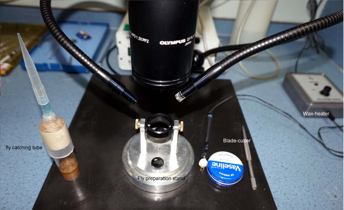
(羽化後)10日齢のハエとSTを含むきれいなフライチューブに配置します - 5を収集andard食品。それも、「新生児」よりも若いハエより良い記録を達成することが可能です。しかし、それらの柔らかい目で、記録電極のため角膜の開口部を切断することはより困難です。チューブをキャッチフライとフライの準備スタンド( 図4)を構築します。これらの自己製のツールがまとめたかの一般的な考え方については、 図4を参照してください。- チューブをキャッチフライを作るために、50ミリリットルのプラスチック遠心分離管の円錐形の底の先端を切り落としました。そして、この新たな開度に1ミリリットルピペットチップの大端を挿入し、接着剤。
- 最後に、容易にフライスルー歩くことができますサイズにピペットの小端をカット。 2軸回転と異なる位置へのフライホルダーのロックを可能にする小さなフライ準備段階を組み立てるために機械的なワークショップを参照してください。

Figur電子4. ツールとクレビスはフライの準備を作成するために必要です。キャッチチューブを50mlプラスチック遠心管に1ミリリットルプラスチックピペットチップを接着することにより行われるフライ。別注フライ準備スタンドはフライを調製するための好ましい位置にフライホルダーの自由な回転とロックを可能にします。ハエは、電気ワックスヒーターを用いて、蜜蝋により固定されています。ワセリンは、ハンドル上に厚いソート髪を接続することによって作られた小さなアプリケータによって適用されている。 この図の拡大版をご覧になるにはこちらをクリックしてください。
かろうじてを通して合うようにフライを可能にする1ミリリットルピペットチップで実験用のフライを収集します。フライチューブに、その上にピペットチップで、フライキャッチチューブを取り付けます。フライをキャッチするには、ピペット先端に上向き(antigravitaxis)を登るために彼らの固有の傾向を利用します。好ましくは、サイズの問題として、最大の女性を選択電気生理学での。
注意:高品質の細胞内記録の可能性の細胞より大きく、フライ大きくて良いです。小さいハエ(雌雄両方)は、優れた録音を提供することができますが、準備は作るのがより困難です。フライは、大きなピペットチップの中に閉じ込められると、逃げるの他のハエを停止するフライ管を閉じることを忘れないでください。ピペットチップの大きな開口への柔軟なプラスチック製のホースと100ミリリットルの注射器を接続 - まだそれでフライに。フライホルダーの底部の開口部に、ちょうどを通してショウジョウバエをできるように拡大され、大きなピペットチップ、上の狭い端部を置き、フライホルダーにフライを排出するために、注射器から空気の小容量を圧迫。- 実体顕微鏡を通して見て、静かにハエの頭がフライホルダーの円錐形の端から突出するまで、より多くの空気を管理します。ハエがしっかりと小さなOPEにその胸部からトラップされていることを確認してくださいフライホルダーの上に寧。
フライホルダーにその「肩」からミツロウでハエを固定するために、ワックスヒーターを使用してください。ワックスを溶融まだきれいに可能な限り低くなるようにワックスヒーターの温度を調整します。
注:温度が正しい場合、ワックスは透明に見えます。温度の高すぎるワックスは「燃え尽きる」になります。低すぎるワックス硬いを保持します。ハエを固定する際に長時間の熱暴露がそれに損傷を与える可能性がある、正確かつ簡潔であること。そのアプリケーションが遅すぎるなどの光硬化歯科用接着剤を使用すると、ここで推奨されていません。

in vivo 実験 のためにフライを準備 図5.。 左 、 ショウジョウバエの頭はまっすぐフライホルダー内に配置し、加熱することで、フライホルダーにその口吻、右眼と肩から固定されています。eswax。 右は 、小さな開口部が鋭利なカミソリのエッジを使用して、ちょうど赤道と離れて戻ってキューティクルからわずか数個眼の上に、目の最も厚い部分で切断されています。角膜の一部を穏やかに除去され、穴は、最大乾燥から目を防ぐために、石油ゼリーで封止されている。 この図の拡大版をご覧になるにはこちらをクリックしてください。
ハエの頭を固定。角膜を避け、吻( 図5)と右眼の隅に蜜蝋を適用し、フライホルダーにこれらの点から頭部を固定します。マイクロナイフを生産します。 2ブレードホルダー/ブレーカ(フラットグリップの両方)を有する非ステンレス製のカミソリの刃をクランプし、その鋭いエッジの小さなストリップをクラック。健康と安全のために、(かみそりが割れているときにピースが跳ね返ることになる可能性はほとんどありませんが)目の保護用ゴーグルを使用します。理想的には、尖塔に似た鋭いカミソリのエッジを生成します。この「尖塔」がしっかりとブレードホルダに装着されていることを確認しますが、任意の自傷しないように注意してください!記録微小電極のための通路を提供するために、ちょうど目の赤道上空背側クチクラから5個眼 - 約4で - マイクロナイフを使用して、フライ左目のいくつかの個眼の小さな開口サイズを用意。高倍率での準備を見て、実体顕微鏡下で実行します。
注:フライアイプロービングに弾性と抵抗感じるので、穴は「尖塔」-knifeで最高のカットです。切断技術は非常に困難であるため、ビデオ・デモに細心の注意を払います。 (フライ準備スタンドに)一定の向きでフライホルダーを保つことは解剖を容易にすることができます。当初、顕微は、学ぶことは難しいと感じるかもしれませんが、コミットされると、神経適応が徐々に研究者の3次元認識と器用さを向上させます。Removeちょうど下に網膜を露出させ、切断した開口部から角膜の慎重小片。迅速にワセリンアプリケータの細かい毛を使用して、石油ゼリーの小さなブロブと目の穴をカバーしています。
注:石油ゼリーは、ここで複数の役割を提供しています。これは、挿入された記録電極を破る体液の組織脱水および凝固を防ぐことができます。それはまた、その壁内の容量を減少させる、微小電極をコートをところで。これは、記録システムの周波数応答を改善し、そのように記録された神経信号の時間分解能ができます。これは光学系をあいまいとして、目の残りの部分の上にワセリンを塗りつけ避けます。
R1-R6感光体またはLMCS 3.録音
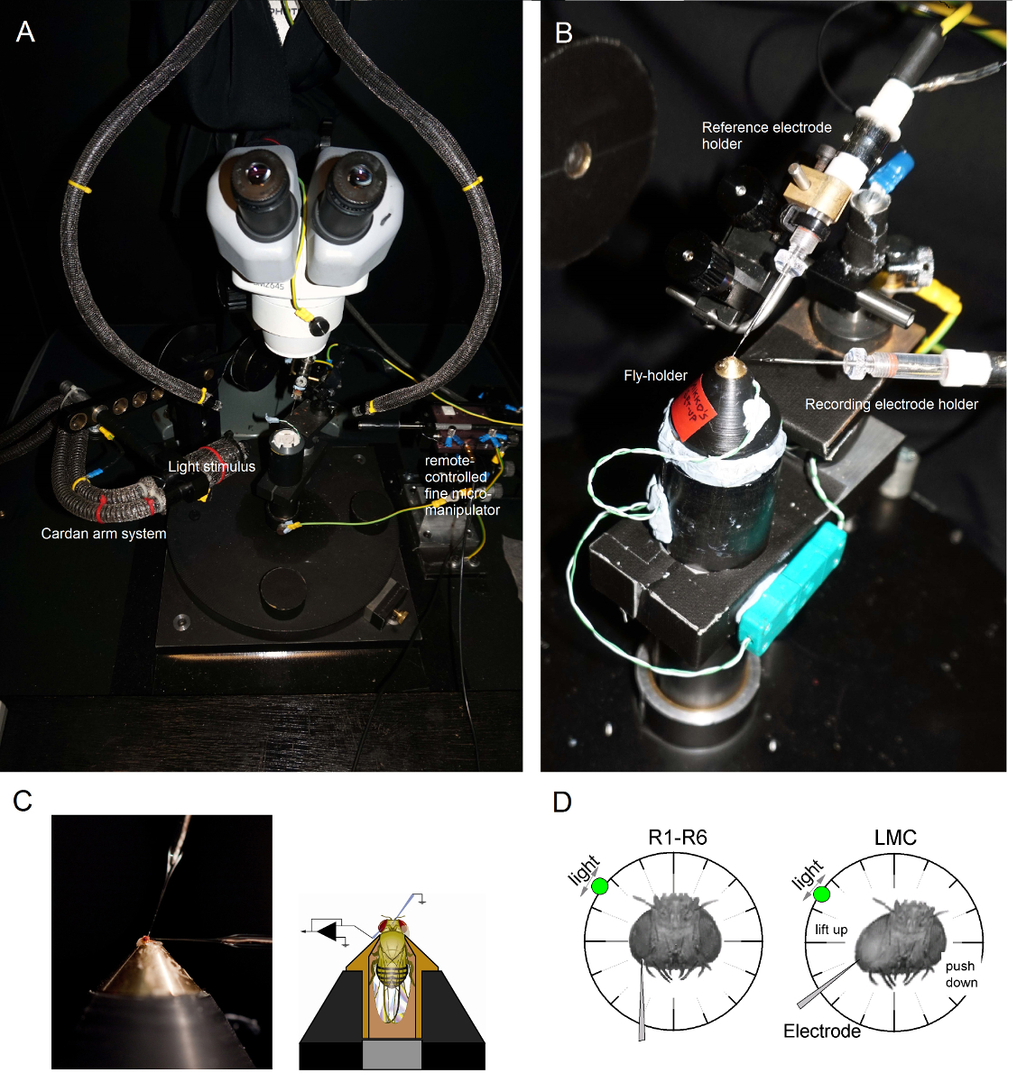
(ファラデーケージや除振台の金属面に触れて、例えば)微小電極アンプを操作するとき、これは誤ってお届けから1を排除するよう、常に、接地します回路が損傷する恐れがヘッドステージに静電荷をる。フライホルダが近い視覚制御下に好ましい位置にポール上に配置することができるように(ファラデーケージの中に冷光源を持つ)2ガチョウの首のライトガイド( 図6A)によって上からフライ準備プラットフォームのポールを照らします。

図6. ポジショニングフライホルダーと実験のための電極 (AB)フライホルダーはまた、ペルチェ素子(A:中央に白い丸いプラットフォーム)を介して温度制御を提供する記録プラットフォーム上に配置されます。カルダン・アームは、光源(液体又は石英光ファイバ束の端)が直接その目を指しているとフライの周りの(x、y-回転を介して)等しい距離での光刺激の正確な位置決めを可能にします。 OUの多くでrのリグは、光刺激が(リニア電流ドライバと)またはモノクロメータによりLEDによって生成されます。このように、彼らの刺激は300の間で選択された特定の(バンド渡された)スペクトル内容、運ぶ - 740 nmのをし、4カバー - 6対数強度ユニットの範囲を(別々のNDフィルターによって減衰されるように)。別々のマイクロマニピュレーターによって制御される(C)二つの微小電極は、ハエの頭の中に配置されている:単眼を介して基準電極を(上記);左目の小さな開口部を介して記録電極(左)。感光記録の最大数を得るために(D)は 、記録用微小電極を穴に駆動され、吻-単眼軸に平行です。感光体への電極チップが貫通及びシールは、自由に回転可能な光源は、セルが所定の光刺激に対する最大電圧応答を生成する位置に固定されているとき。空間でのこの点は、細胞の受容野の中心に位置しています。穴私の場合キューティクルに近いのは、LMCの貫通部は、さらに、この同じ電極角(左)を用いて達成することができます。穴はキューティクルから遠い場合は、LMCの録音を得るための別の有用な電極進入角も(右)が示されている。 この図の拡大版をご覧になるにはこちらをクリックしてください。
フライ準備プラットフォームポールに(その中にフライで!)フライホルダーをマウントします。フライ左目が直接捜査官( 図6B)を向くようにフライホルダーを回転させます。実体顕微鏡( 図6C)を介しての準備を観察しながら、小さな粗いマイクロマニピュレーターを用いて、頭部カプセルにフライoccelliを通して穏やか鈍参照電極を挿入します。これはハエの脳に損傷を与えることができるよう、あまりにも深い電極を押さないでください。- 代替的に、胸部の背面に参照電極を挿入します。常に、フライはヒースが多く生えた表示されます(そのアンテナを移動させ)、その目は無傷であることを確認してください。誤って破損していません。準備が真っ白未満に見える場合は、実験のための新しいフライを準備します。
ワセリンを介して左眼に鋭い記録微小電極を駆動するには、先に用意小さな開口部をカバーしました。実体顕微鏡で高倍率を使用し、電極先端の位置は、その反射率パターンによって3Dで明らかになるように光ガイドと焦点面を移動します。
注: 図6Dは、感光体とLMC録画に(角度 に対する記録微小電極が目に入った)ハエの頭がわずかに異なる位置に配置する方法を示しています。それを壊すことなく、目の中に電極を駆動すると、実験の最も困難な段階です。電極先端が角膜を打つ、眼の中の小さな開口部をミスした場合、それは一般的に破壊します。微小電極増幅器をオンにします一度両方の電極は、フライの体液と電気的に接触して、製剤の内部にしっかりとしています。(ファラデーケージ内)冷光源の電源を切り、コンセントからプラグを抜きます。グラウンド・ループ誘導される電気ノイズを最小限に抑えるために中央の地面にそのプラグを接続し、カルダンアームシステムが自由にフライの周りに移動させることができるように離れたガチョウの首の光ガイドを移動します。フライの準備が相対暗闇の中であることを保証するために、部屋の照明のスイッチをオフにします。(アンプのユーザーマニュアルの指示通り)の目に記録電極の抵抗値を測定します。 250MΩ - 抵抗値が100であるだけ記録電極を使用してください。
注:<70MΩ電極により、高品質な細胞内記録を達成することは事実上不可能です。抵抗値が<80MΩである場合には、電極チップが壊れている可能性があります。この場合は、アンプの電源を切り、記録電極を変更します。- 電極いったん置き換えと目で、その抵抗を測定するために、アンプのスイッチをオンにされています。それが組織に入るように時々、電極先端は、いくつかの残骸によってブロックされてしまうことができます。これは、典型的には、急速な共振や反発によってそれをクリアし、アンプの容量話題と電流パルスの関数を使用することによって改善することができます。
電流クランプ(CC)またはブリッジの記録モードにアンプを設定します。両者は現在ゼロオフセット信号(記録用電圧)を設定することにより、電気的に相互接続された細胞外空間に載っているように、記録と参照電極の間の任意の電圧差を打ち消します。アンプの表示読み出しまたはオシロスコープの画面を使用して、信号オフセットの変更に従ってください。暗適応へのフライアイのために2〜3分待ちます。小さな0.1から1ミクロンの手順で眼内に徐々に深く記録電極チップを駆動します。リモートコントロールマイクロマニピュレーターまたはbのx軸ピエゾステッパーでこれを行いますyは静かに手動マニピュレーターの細かい解像度ノブを回し。記録電極は、組織内で進められているように - (10ミリ秒1)光点滅短いとフライアイを刺激します。
注:記録電極は、網膜内に配置され、目の機能は、通常、各光フラッシュは電圧が短時間と小滴原因となります場合(0.2から5 mVの過分極)、(ERG)電と呼ばれます。細胞外空間の電場電位の変化は、光に網膜細胞の集団応答によって引き起こされます。電極の先端が薄層に入るとしかし、LMCSに閉じ、ERGは、脱分極応答を示す、反転させます。カルダンアームシステムを使用して、フライアイ周りに光源を移動し、光が最大のERG応答を呼び起こす位置を見つけます。
注:この位置は、次の記録電極の先端に位置している光受容体(またはLMCS)視覚空間の小さな領域をマーク、それらの光入力をサンプリング。記録電極を細胞に浸透します。
浸透が自然に発生する可能性があり、または電極である場合、前方マイクロ段:注意してください。さらに静かにマイクロマニピュレータシステムをタップするか、または増幅器のバズ関数を使用することによって容易にすることができます。これらのアクションは、組織内の電極先端を共振します。電極は、感光膜をimpalesとき、その細胞内空間、記録と参照電極との間の電圧差を入力すると、急激に低下0 mVでのmVの〜-65(-55及び-75 mVの間)。 LMCの貫通中のに対し、このドロップは(-30〜-50 mVの間)は、典型的には、以下です。これらの電圧差は、与えられた細胞の負の静止電位を表します。記録電極(その鋭さ)、それを貫通細胞プロセスの品質に応じて、記録電極からの電圧読み出しは、細胞膜のように、静止電位に迅速にまたは徐々に安定させることができます電極の外側の層にシール。浸透は部分的にしか、または悪い場合でも、電極は、通常、バック、ゼロに向かって記録された潜在的な登山を有する細胞の外に滑ります。安定した膜電位(ダーク静止電位)を示す、電極が適切に密封された表示され浸透し、細胞の受容野の中心をローカライズ。光フラッシュは、セルの最大電圧応答を呼び起こす視覚空間内のポイントを見つけるために、カルダンアームシステムを使用して、フライアイの周りに点滅する光刺激を移動します。光刺激が直接受容野中心(点を)対向したときカルダンアームをロックします。
注:暗闇の中では、 ショウジョウバエの光受容体は、40で明るい光パルスに反応する-安定LMC記録は20〜45 mVの過分極応答9,10,14を示しながら、65 mVの脱分極電圧応答4,5。グリア貫通は、めったに起こらない<-80 mVの休止電位によって示され、はるかに遅いことがあり小さい(〜5 mVの)光誘起脱分極を飽和させました。このような白い目7と朱色など、さまざまな眼の色素沈着、とショウジョウバエの光受容体は、野生型に匹敵する応答の大きさを示しています。その膜の充電中に記録アーチファクトを最小限にするために研究し細胞内に - (200ミリ秒100)電流パルスアンプの電流クランプ(CC)モードを使用して、小さな0.1 nAのと簡単なを注入することにより、記録電極の静電容量を補償します。
注:この重要な手順は、アンプの取扱説明書で詳細に説明されており、実際の実験の前に、電気的な細胞モデルを用いて実施されるべきです。(このような自然光強度の時系列またはランダムなコントラストパターンなど)様々な統計的または物理的性質を有する光パルス及び関心のある他の刺激に対するレコード電圧応答。試験は、例えば、どのように記録された応答は、軽または暗順応に変更します。
注:一つは李正確にすることができます光路4,5にNDフィルターを追加することにより、予め選択された強度の連続光によって研究細胞をGHT-適応させます。また、長時間の暗順応のために予め設定された時間のための光刺激をオフにします。そのため記録システムの機械的安定性、記録電極の高品質と準備の無傷の、安定した記録条件は、時には何時間も続くことができます。従って、良好な日には、単一のセルとは異なる適応条件で大量のデータを収集することが可能です。電極は、セルのうちスリップ時、記録された応答が減少し、平均電圧はゼロに近づき始めます。電極が接触すると、次のセルを貫通するまで(これは一般的に最も近い神経隣人である)を慎重にマイクロマニピュレータの微細なx軸制御と記録電極を進めます。これらの演習は、PL」電極になるだろうとして、y軸またはz軸に沿って電極を移動しないでください組織「横ウワーッ、眼の構造に損傷を与えます!
注:良い電極と健康的な準備で、1は数時間にわたって同じフライで多くの光受容体からの(まれに多くのLMCSから)高品質の応答を記録することができます。時折、クリア信号劣化させることなく、全体の営業日(> 8時間)を超えます。定期的に、日付、遺伝子型、および記録された細胞型として、識別情報とデータファイルを保存します。ために成功記録セッション中に収集することができ、大量のデータを、将来のデータ分析のためのラボブックに良い書かれた記録を保持。
結果
鋭い微小電極記録方法は、 ショウジョウバエの眼のためにここに適合したように、確実に神経情報サンプリングおよび処理網膜および薄層細胞において、それらの間の通信4,5,7,8,10,33を定量化するために使用することができます。別の野生型株、変異体または遺伝子操作フライ株における符号化を研究するためにそれを使用することにより、この方法は、その価値を証明しています。だけでなく、突然変異、温度、食事または選択した式3,4,6,9,10,14,30,34の効果を定量化ではなく、変更された視覚的な行動14,34のための機構的な理由を明らかにしました。この方法はまた、neuroethologicalビジョンの研究に力を与える他の昆虫の製剤35,36、に容易に適用可能です。次に、その成功したアプリケーションのいくつかの例を紹介しました。

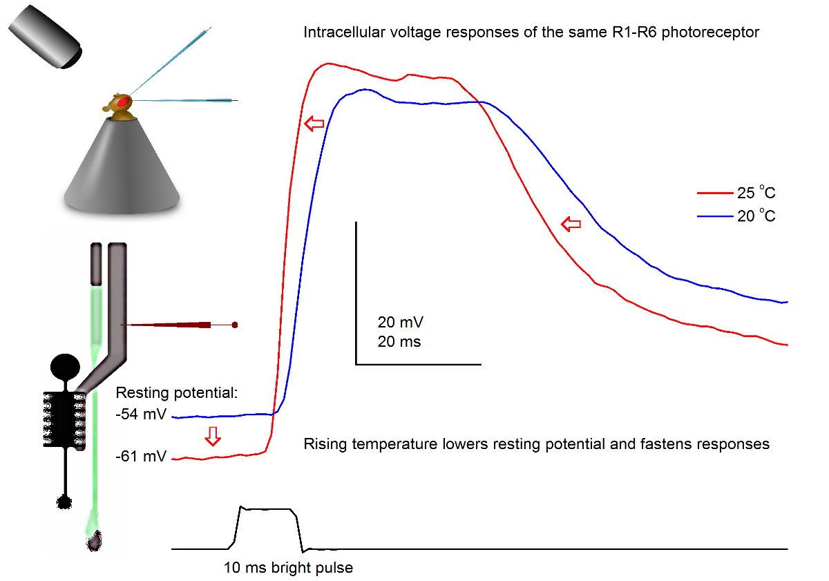
図7. 電圧20および25 O℃で光パルスにミバエR1-R6感光体の応答鋭い微小電極の貫通部には、多くの場合、非常に安定しているので、で与えられた光刺激に対して同じR1-R6の感光体の電圧応答を記録することができますハエを温めるまたは冷却することにより、異なる周囲温度。我々のセットアップでは、フライホルダーは閉ループペルチェ素子に基づく温度制御システムに配置されています。これは、秒単位でハエの頭の温度を変更することを可能にします。より高い温度は、電圧応答を加速し、特徴(赤い矢印で示されているように)R1-R6の光受容体の静止電位を低下させる。 この図の拡大版をご覧になるにはこちらをクリックしてください。
感光体の出力に及ぼす温度の影響を研究
うまく設計及び振動絶縁記録システムでは、この方法は、加温することにより、個々の細胞の神経出力に対する温度の影響を測定するか、フライを冷却するために使用することができます。与えられた例では、20と25°Cの ( 図7)で同じR1-R6の感光体に記録された明るい10ミリ秒の長パルス、に電圧応答を示します。 4.9前に定量化されるように、温暖化は暗闇の中で光受容体の静止電位を低下させ、その電圧応答を加速します。

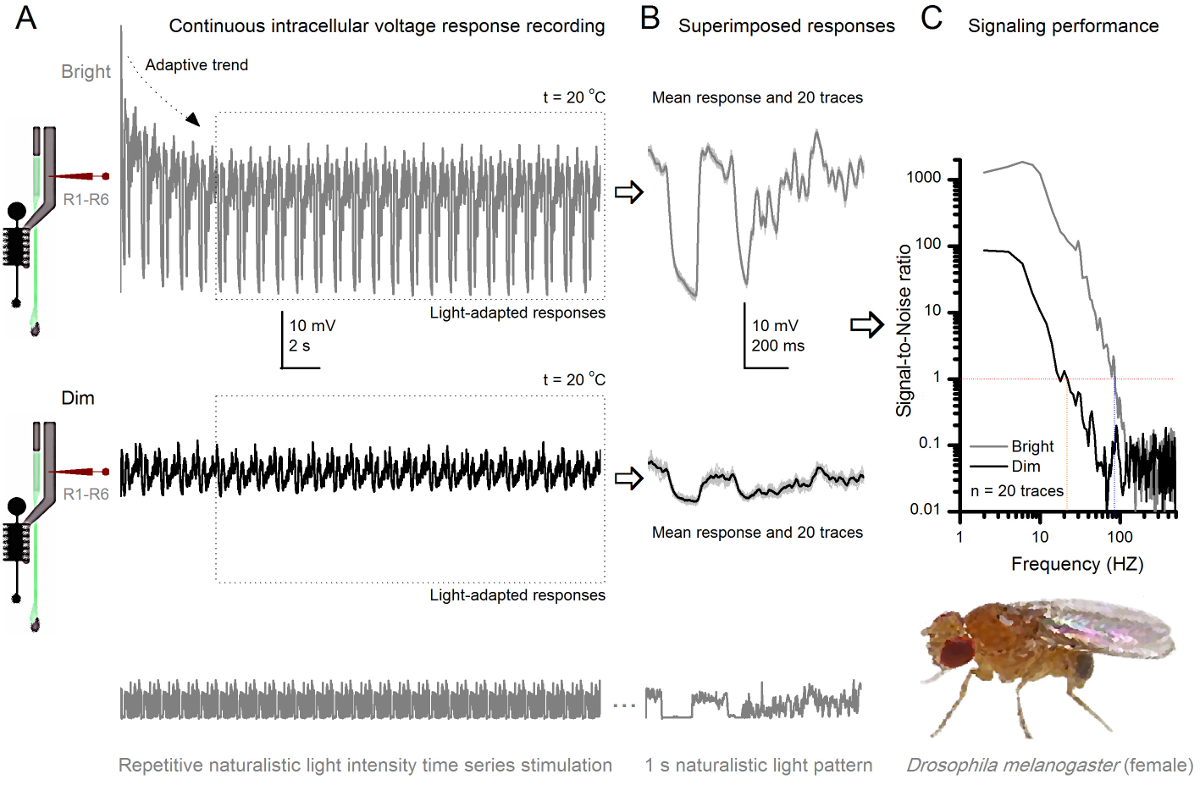
フルーツフライR1-R6感光体は、光強度に向上しました 図8. シグナリングパフォーマンス (A)感光体の出力(下)暗くし、明るい(上記; 10,000倍明るい光)。同じ微小電極によって記録された自然光強度の時系列を繰り返します20 O℃で同一セル内彼らはより多くのサンプル、単一光子4,5,7,8に基本応答(バンプ)を統合するので、明るい刺激に対する応答は、大きくなっています。 (B)20の連続した1秒の長電圧応答が重畳されています。適応傾向は(Aの矢印)(Aの破線ボックス)後退した後、個々の応答(ライトグレー)を採取しました。対応する応答手段(信号)が暗くトレースです。信号と個々の応答との間の差は、ノイズです。 (C)細胞を、標準的な方法4,5,7,8を用いて信号対雑音比(SNR)」シグナリング性能を記録することによって定量化しました」。感光体の出力がsで、 '(20ヘルツまでの薄暗い ≥1、薄暗いSNR)よりも(84ヘルツまでの明るい ≥1、明るい刺激SNR)'での信頼性のシグナル伝達の約64 Hzの広い範囲を持っていますignal対雑音比が大幅に向上します。 SNR 薄暗い MAX = 87からのSNR ブライト MAX = 1868へ。 この図の拡大版をご覧になるにはこちらをクリックしてください。
反復刺激によって適応と神経エンコーディングを学びます
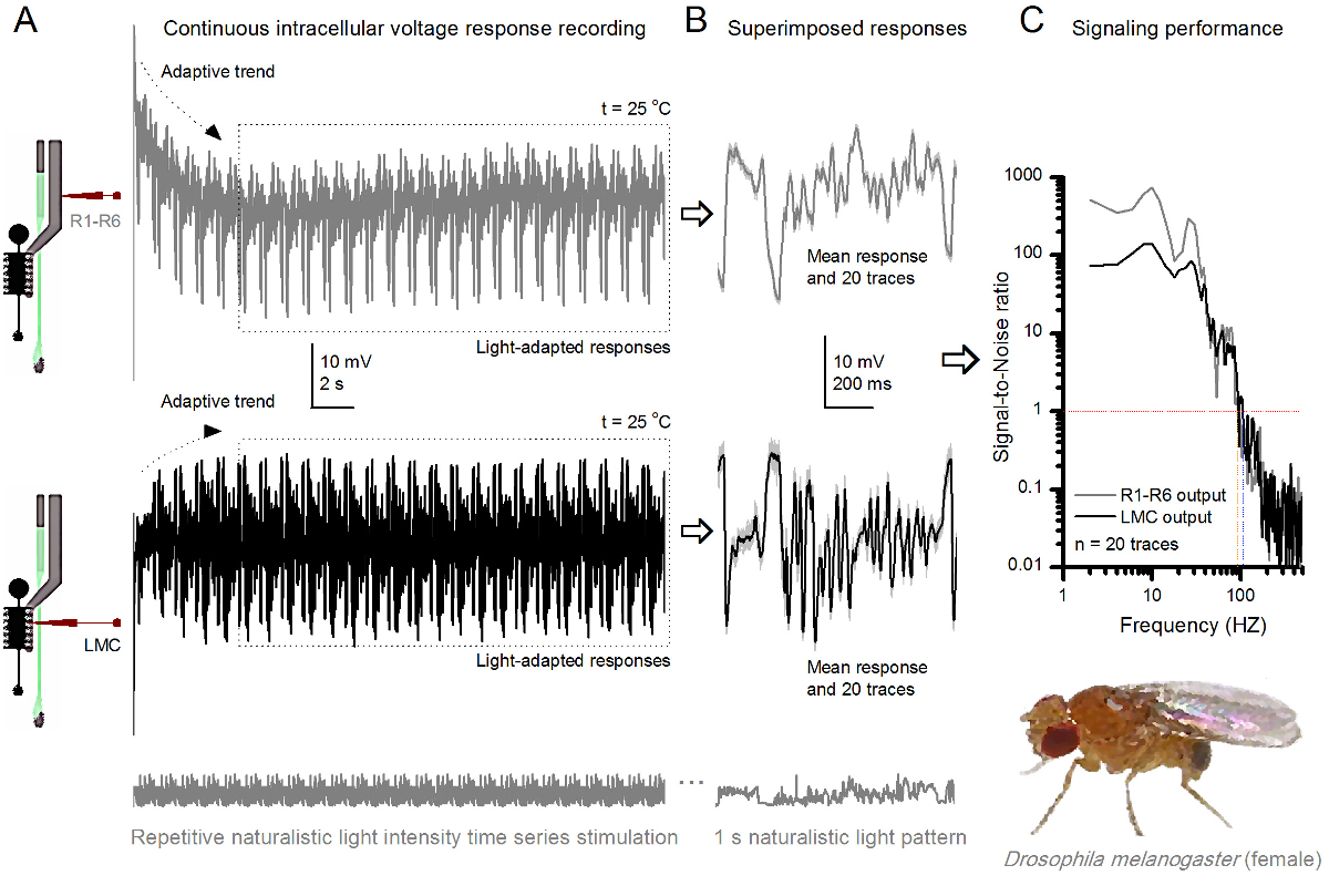
網膜およびラミナ構造で比較的少ない損傷を引き起こす方法の非侵襲性は、in vivoでの彼らの近くに自然の生理的状態の異なる光刺激に対する個々の細胞の信号伝達性 能を研究するために理想的です。8に示すR1-の電圧応答を図 20°Cので暗く、明るい繰り返さ自然光強度の時系列刺激に対するR6の感光体、 図9のに対し、 25 O℃で異なる自然刺激に別のR1-R6の感光体とLMCの応答を示します同じフライで2鋭い微小電極、網膜内の1とラミナ内の他の同時細胞内記録は、30生存可能であるには余りにも困難であるため、前とシナプス後録音は、二つの異なるハエとは別に行われました。

別のハエとは異なる微小電極によって記録された25℃。(A)R1-R6(灰色)およびLMC(黒)出力で繰り返さ自然主義的刺激へのミバエR1-R6感光体とLMCの 図9 の電圧応答 。 (B)光に示す完全に明順応連続20前(上)と個々の応答と同じ自然な刺激パターンにシナプス後(下)の応答を、灰色暗いトレースとしてDに対応する応答手段(信号)。信号と個々の応答との間の差は、ノイズです。 (C)細胞信号対雑音比(SNR)」シグナリング性能を記録することによって定量化しました」。 LMC出力は'(R≥1、94ヘルツまでのR1-R6の出力SNR)よりも(104ヘルツまでLMC≥1、信頼性の高いシグナリングSNR)」の約10 Hzの広い範囲を持っています。両方の信号対雑音比が高い(SNR LMC MAX = 142、SNR R MAX = 752)、記録ノイズが低かったとして、その違いは、細胞間の実際のエンコーディングの違いを反映している。 の拡大版をご覧になるにはこちらをクリックしてください。この図。
刺激開始後、録音典型的なLY大部分は5-6秒以内に治まる高速適応傾向を示します。その時から、細胞が(各点線のボックスは、これらの20を囲む)各1秒長い刺激提示に非常に一貫性のある応答を生成します。これらは( 図8Bおよび図9B)重畳されたときの応答の再現性が明白になります。個々の応答は、薄い灰色の痕跡であり、その厚い暗いトレースを意味します。 神経雑音は、平均、各個々の応答4,5,9,37,38との差であるのに対し、平均応答は、 神経信号として取り出されます。周波数領域でそれぞれの信号対雑音比( 図8C及び図9C)は 、パワースペクトルに信号とノイズデータチャンクをフーリエ変換し、対応する平均雑音パワースペクトル4との平均信号パワースペクトルを分割することにより得られました5,9,37,38。特徴的に、最大の信号対雑音比O自然な刺激に記録された神経の出力は(100 -千)高いF(。 例えば 、 図8C)、および非常に低い記録ノイズで最も安定した製剤中の値>>千に達することができます。通知はまた、温暖化は'( ブライト ≥1セル信頼性のシグナル4 SNR)の帯域幅」を展開します。例えば、 図8 及び図9中の2つのR1-R6sとの間の相対的な差は、それぞれ、10ヘルツ(84、20 O Cと94ヘルツ25 O Cで)です。
一つは、さらに、シャノンの式32を使用することによって、または三重外挿法39を介して応答'エントロピー及び雑音エントロピーレートの差を計算することにより、その信号対雑音比の情報転送の各セルの速度を推定することができます。情報理論解析、およびそれらの使用および制限に関する詳細具体的には、この方法では、Sは、以前の刊行物7,8,39に示されています。

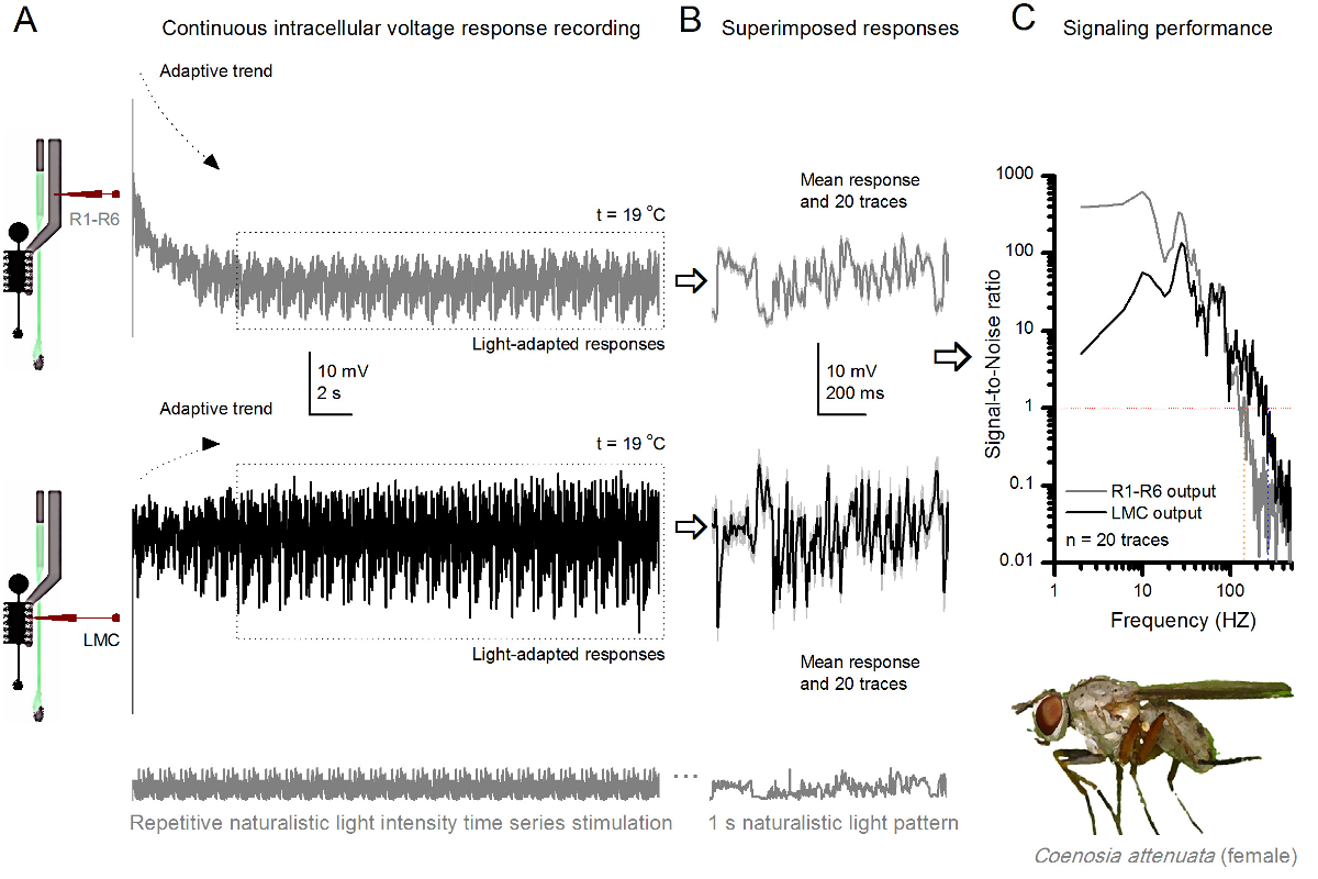
19℃。(A)R1-R6(灰色)およびLMC同じフライから同じ微小電極によって記録(黒)出力で繰り返さ自然主義的刺激へのキラーフライR1-R6感光体とLMCの 図10 の電圧応答 。電極が目に進めたとして、後シナプス前最初のシナプス後部と、。同じ自然な刺激パターンに(B)20の連続した前(上)とシナプス後(下)の応答(ライトグレーのトレース)は、最初の適応(Aの点線のボックス)の後に捕獲されました。個々の応答に、それぞれの違いは、ノイズを与えながら、その手段は、信号(上部の暗いトレース)です。 (C)に対応するシグナリットル対ノイズ比(SNR)は 、図8C及び図9Cのように計算しました。 LMC出力が'(134ヘルツまでのR MAX≥1、SNR)R1-R6の出力よりも(234ヘルツまでのLMC MAX≥1、信頼性の高いシグナリングSNR)」の100 Hzの広い範囲について持っています。両方の信号対雑音比は、(SNR LMC MAX = 137、SNR R MAX = 627)高く、同じ微小電極がレコーディングに使用されたとして、その違いは、前と後シナプス神経出力の本当の違いを反映しています。これらの結果は、記録システムは、低ノイズを持っていた、と分析への影響が限界であったことを示唆している。 この図の拡大版をご覧になるにはこちらをクリックしてください。
Neuroethologicalビジョン研究
この方法はまた、視覚情報の処理の比較neuroethological研究を可能にする、異なる昆虫種の化合物の眼7,8,35,36( 図10)から前およびシナプス後電位の応答を記録するために使用することができます。提示記録システムの場合、唯一の必要な適応を検討した種のための適切なサイズの開口部を有する新規作成ホルダー、それぞれです。これらの例示的な録音は女性キラーフライ(Coenosiaのattenuata)のからのものです。彼らは、 図9のショウジョウバエの対応のために使用されるように、同一の繰り返し光刺激に対するR1-R6の感光体とLMCの細胞内の電圧応答を示すが、19℃。でこの場合、前およびシナプス後データの両方を同じ場から記録しました。 1第1の横の薄層を進行(3 M KClで満たされた)同じ記録電極と、他の前に入力した後、正面網膜る。でも、クーラーの温度で- - 25°Cの 、Coenosiaデータでのショウジョウバエのデータと比較してより高速なダイナミクスと応答を示しています。広い周波数範囲にわたって信頼できるシグナリング(信号対雑音比>> 1)の範囲を拡大します。自然刺激の神経符号化におけるこのような機能的適応は高速空中狩猟行動を達成するために高精度な時空間情報を必要とCoenosiaの捕食ライフスタイル36、と一致しています。
ディスカッション
We have presented the basic key steps of how to use sharp conventional microelectrodes to record intracellular responses of R1-R6 photoreceptors and LMCs in intact fly eyes. This method has been optimized, together with bespoke hardware and software tools, over the last 18 years to provide high-quality long-lasting recordings to answer a wide range of experimental questions. By investing time and resources to construct robust and precise experimental set-ups, and to produce microelectrodes with favorable electrical properties, high-quality recordings can become the norm in any laboratory working on Drosophila visual neurophysiology. Whilst well-designed recording and light stimulation systems are important for swift execution of different experimental paradigms, there are three procedural steps that are even more critical to achieving successful recordings: (i) to make the fly preparation with minimal eye damage, (ii) to pull microelectrodes with the right electrical properties, and (iii) to drive the recording electrode into the eye without breaking its tip. Ultimately, to record meaningful data, the investigator has to understand the physical basis of electrophysiology and how to fabricate suitable microelectrodes for the targeted cell-types.
Therefore, the limitations of this technique are primarily set by the patience, experience and technical ability of the investigator. Because this technique can take a long time to master for small Drosophila cells, it is advisable for trainee electrophysiologists to first practice with larger insect eyes, such as the blowfly36 or locust35, using the same rig. Once performing high-quality intracellular recordings from the larger photoreceptors and interneurons becomes routine, it is time to move on to the Drosophila eye. Another limitation of the technique concerns cellular identification. Penetrated Drosophila cells can be loaded electrophoretically with dyes, including Lucifer yellow or neurobiotin. However, because of the small tip size of the microelectrodes, electrophoresis works less efficiently than with lower resistance electrodes, such as patch-electrodes. Furthermore, the dye-filled microelectrodes characteristically have less favorable electrical properties, making it much harder to record high-quality responses with them from Drosophila photoreceptors and LMCs.
A technical problem that occurs sometimes is unstable input signal, or a complete lack of it. This is often associated with the voltage signal being either constantly drifting or higher/lower than the amplifier's recording range. On most occasions, this behavior is caused by the recording electrode being blocked (or its tip being too fine - having too high a resistance or intramural capacitance - to properly conduct fast signal changes). Although one can try to unblock the tip by buzzing the electrode capacitance, which sometimes works, often the situation is best resolved by simply changing the recording electrode. This may further require parameter adjustments in the microelectrode puller instrument to lower the tip resistance of the new electrodes. The electrode tip can also become blocked in preparations, for which it took too much time to cover the corneal hole by petroleum jelly. Prolonged air-contact can dry up the freshly exposed retinal tissue, turning its surface layer into a glue-like substance. If this is the case, the investigator typically sees a red blob of tissue stuck on the recording electrode when pulling it out of the eye. The only solution here is to make a new preparation. Petroleum jelly may provide many benefits for electrophysiological recordings: (i) it prevents the coagulation of the hemolymph that could break the electrode tip; (ii) it coats the electrode tip reducing its intramural capacitance, which lowers the electrode's time constant, and thus has the potential to improve the temporal resolution of the recorded neural signals40,41; (iii) it keeps the electrode tip clean, facilitating penetrations; and after penetration, (iv) it may even help to seal the electrode tip to the cell membrane42.
The signal can further be unstable or lost when the silver-chloride wire of the electrode-holder is broken or dechloridized; in which case just replace or rechloridize the old wire. The missing signal can also result from one (or both) of the electrode-holders not being securely connected to their jacks. However, it is extremely unusual that a piece of equipment would be malfunctioning. If signal is undetectable and all other possibilities have been exhausted, test that each part of the recording apparatus, including the headstage, amplifier, low-pass filters and AD/DA-converters, are connected properly and functioning normally. One way to achieve this is to replace each instrument with another from a rig that is known to operate normally. Alternatively, use a signal generator to check the performance of the electronic components one by one.
But perhaps the most common technical problem facing the electrophysiologist is that of recording noise. Broadly, recording noise is the observed electrical activity other than the direct neuronal response to a given stimulus. Because the fly preparation, when properly done, is very stable, the observed noise (beyond the natural variably of the responses) most often results from ground-loops in the recording equipment, or is picked up from nearby electrical devices. Such noise is typically 50/60 Hz mains hum and its harmonics; but sometimes composed of more complex waveforms. To work out the origin of the noise, remove the fly preparation holder from the set-up, connect the recording and reference electrodes through a drop of fly Ringer (or place them in a small Ringer's solution bath; see step 1.2.6) and record the signal in CC- or bridge-mode. If noise is observable on the recorded signal, this likely means that the noise is external to the fly preparation.
Another good test for identifying the origin of noise is to replace the electrode-holders with an electric cell model connected to the amplifier. In an ideally configured and grounded set-up, the recorded signal should now be practically noise-free, showing only stochastic bit-noise from the AD-converter (in the best case not even that!). If noise is still present, then recheck that all rig equipment is properly grounded. A convenient approach to detect ground-loops is to: (i) disconnect all the grounding wires from all the parts within the rig; (ii) ensure that, after doing this, every single part is actually isolated from ground, by means of an ohm-meter; (iii) connect the parts, one by one, to the central ground directly, not through any other part of the rig. Try also changing the equipment configurations. For example, sometimes moving the computer and monitor further away from the rig can reduce noise; yet at other times, moving the computer inside the equipment rack reduces noise. It is also worth unplugging nearby equipment to see if noise is reduced, or shield additional components. Furthermore, try unplugging or replacing different components of the recording equipment, especially BNC cables (which can have faulty ground connections). If only bit-noise is observed when using the cell model, the initial noise source is either the electrodes or the fly preparation itself. For example, it could be that the reference electrode is inadvertently touching a motor nerve or active muscle fibers inside the head capsule (or disturbing flight muscles in the thorax - if placed there). It is usually simplest to prepare a new fly for recording, taking care to minimize damage to the fly. But if the noise persists and is broadband, it is likely that the electrodes are suboptimal for the experiments; too sharp/fine (hence too noisy) or just wrong for the purpose; we have even seen quartz-electrodes acting as antennas - picking up faint broadcasting signals! Although iteration of the puller-instrument parameter settings to generate the just right microelectrodes for consistent high-quality recordings from specific cell-types can take a lot of effort, it is worth it. Once the recording electrodes are well-tailored for the experiments, they can provide long-lasting recordings of outstanding quality.
Sharp microelectrode recording techniques can be similarly applied to study neural information processing in multitude of preparations, including different processing layers in the insect eyes and brain43,44. Because the microelectrode tips can be made very fine, these typically damage the studied cells less than most patch-clamp applications. Importantly, the modern sample-and-hold microelectrode amplifiers enable good control of the tips' electrical properties40,45-47. Thus, when correctly applied, this technique can provide reliable data from both in vivo3,5,7-10,44 or in vitro48 preparations with high signal-to-noise ratio at sub-millisecond resolution. Such precision would be impossible with today's optical imaging techniques, which are noisier and slower. Moreover, the method can be used to characterize small cells' electrical membrane properties both in current- and voltage-clamp configurations5,29,33,36,40-42,49, providing valuable data for biophysical and empirical modeling approaches7,8,11,33,49-54 that link experiments to theory.
開示事項
The authors have nothing to disclose
謝辞
The authors thank Mick Swann, Chris Askham and Martin Gautrey for their important contributions in designing and building many electrical and mechanical components of the rigs. MJ's current research is supported by the Biotechnology and Biological Sciences Research Council (BBSRC Grant: BB/M009564/1), the State Key Laboratory of Cognitive Neuroscience and Learning open research fund (China), High-End Foreign Expert Grant (China), Jane and Aatos Erkko Foundation Fellowship (Finland), and the Leverhulme Trust grant (RPG-2012-567).
資料
| Name | Company | Catalog Number | Comments |
| Stereo Zoom Microscope for making the fly preparation | Olympus | SZX12 DFPLFL1.6x PF eyepieces: WHN30x-H/22 | Capable of ~150X magnification with long working distance; bespoke heavy steel table mount stand |
| Stereomicroscope in the intracellular set-up | · Olympus | Olympus SZX7; eyepieces: WHN30x-H/22 | 30X eyepieces are needed for seeing the electrode tip reflections well when driving it through the small corneal hole into the eye |
| Nikon microscope | Nikon SMZ645; eyepieces: C-W30x/7 | ||
| Anti-vibration Table | Melles Griot | With metric M6 holes on the breadboard | Our bespoke rigs have a large hole drilled through the thick breadboard that lets in the fly preparation platform pole (houses a copper heatsink with electronics) from below |
| Newport | |||
| Micromanipulators | Narishige | Narishige NMN-21 | In our intracellular set-ups, different micromanipulator systems are used for driving the shap recording electrodes into the fly eye. All the listed manipulators are succesfully providing long-lasting stable recordings from Drosophila photoreceptors and LMCs. |
| Huxley Bertram | Huxley xyz-axis with fine manual control | ||
| Sensapex | Sensapex triple axis | ||
| Märzhäuser | Märzhäuser DC-3K with additional x-axis piezo stepper and MS 314 controller | ||
| Magnetic Stands | Any magnetic base with on/off switch will do | For example, to manage cables inside the Faraday cage | |
| Electrode Holders | Harvard Apparatus | ESP/W-F10N | |
| Silver Wire | World Precision Instruments | AGW1510 | 0.3 - 0.5 mm diameter; needs to be chloridized for the electrode holders |
| Fiber Optic Light Source | Many different, including Olympus | ||
| Fiber Optic Bundles | UltraFine Technology | To deliver the LED light stimulus to the Cardan arm system. We use both liquid and quartz light guides (range from UV to IR) | |
| Thorn Labs | |||
| Fly Cathing Tube | P80-50P 50ml Cent. Tube PP., Pack of 100 Pcs | Cut the conical bottom off from 50 ml Plastic Centrifuge Tube and glue a 1 ml pipette tip on it. | |
| Digital Acquisition System | National Instruments | ||
| Single-electrode current/voltage-clamp microelectrode amplifier | npi SEC-10LX | http://www.npielectronic.de/products/amplifiers/sec-single-electrode-clamp/sec-10lx.html | Outstanding performer! |
| Head-stage | Standard (+/- 150 nA) | For npi SEC-10LX | |
| LED light sources and drivers | 2-channel OptoLED (Cairn Research Ltd., UK) | Many of our stimulus systems are in-house built | |
| Self-designed and constructed | |||
| Acquisition and Analyses Software | Many companies to choose from | Biosyst; custom written Matlab-based system for experimental and theoretical work in the Juusola laboratory | |
| Personal Computer or Mac | Ensure that PC or Mac is compatible with data acquisition system and software | ||
| Cardan arm system | Self-designed and constructed | Providing accurate x,y,z-positioning of the light stimuli | |
| Peltier temperature control system | Self-designed and constructed | ||
| Faraday Cage | Self-constructed | Electromagnetic noise shielding | |
| Filamented Borosilicate Glass Capillaries | Outer diameter: 1 mm | ||
| Inner diameter: 0.5 - 0.7 mm | |||
| Filamented Quartz Glass Capillaries | Outer diameter: 1 mm | ||
| Inner diameter: 0.5 - 0.7 mm | |||
| Pipette Puller | Sutter Instrument Company | Model P-2000 laser Flaming/Brown Micropipette Puller | For borosilicate reference electrodes, use the preset program #11 (patch electrodes): Heat = 350; Filament = 4; Velocity 36; Delay = 200).1.2.1). For borosilicate recording electrodes, use the preset program #12 (this typically pulls good conventional sharps for photoreceptor recordings): Heat = 355; Filament = 4; Velocity 50; Delay = 225; Pull = 150. For LMC recordings, which require electrodes with finer tips, these values need to be adjusted. For pulling quartz capillaries, P-2000 manual suggests programs for fine tipped microelectrodes. These programs’ preset parameters serve as useful starting points for systematic modifications to generate electrodes with good penetration success and low recording noise. |
| Extracellular Ringer Solution for the reference electrode | Chemicals from Fisher Scientific | 10326390, NaCl 10010310, KCl 10147753, TES 10161800, CaCl2 10159872, MgCl2 10000430, sucrose | See the recipe in the protocol section |
| 3 M KCl solution for filling the filamented recording microelectrode | Salts from Fisher Scientific | 10010310, KCl | |
| Petroleum jelly | Vaselin | ||
| Non-stainless steel razor blades | |||
| Blade holder/breaker | Fine Science Tools By Dumont | 10053-09 | 9 cm |
| Blu-tack | Bostik | Alternatively, use molding clay | |
| Forceps | Fine Science Tools By Dumont | 11252-00 | #5SF (super-fine tips) |
参考文献
- Meinertzhagen, I. A., O'Neil, S. D. Synaptic Organization of Columnar Elements in the Lamina of the Wild-Type in Drosophila-Melanogaster. J Comp Neurol. 305, 232-263 (1991).
- Rivera-Alba, M., et al. Wiring Economy and Volume Exclusion Determine Neuronal Placement in the Drosophila Brain. Curr Biol. 21, 2000-2005 (2011).
- Abou Tayoun, A. N., et al. The Drosophila SK Channel (dSK) Contributes to Photoreceptor Performance by Mediating Sensitivity Control at the First Visual Network. J Neurosci. 31, 13897-13910 (2011).
- Juusola, M., Hardie, R. C. Light adaptation in Drosphila photoreceptors: II. Rising temperature increases the bandwidth of reliable signaling. J Gen Physiol. 117, 27-41 (2001).
- Juusola, M., Hardie, R. C. Light adaptation in Drosophila photoreceptors: I. Response dynamics and signaling efficiency at 25 degrees. C. J Gen Physiol. 117, 3-25 (2001).
- Pantazis, A., et al. Distinct roles for two histamine receptors (hclA and hclB) at the Drosophila photoreceptor synapse. J Neurosci. 28, 7250-7259 (2008).
- Song, Z., Juusola, M. Refractory sampling links efficiency and costs of sensory encoding to stimulus statistics. J Neurosci. 34, 7216-7237 (2014).
- Song, Z., et al. Stochastic, Adaptive Sampling of Information by Microvilli in Fly Photoreceptors. Curr Biol. 22, 1371-1380 (2012).
- Zheng, L., et al. Feedback network controls photoreceptor output at the layer of first visual synapses in Drosophila. J Gen Physiol. 127, 495-510 (2006).
- Zheng, L., et al. Network Adaptation Improves Temporal Representation of Naturalistic Stimuli in Drosophila Eye I Dynamics. Plos One. 4, (2009).
- Hardie, R. C., Juusola, M. Phototransduction in Drosophila. Curr opin neurobiol. 34, 37-45 (2015).
- Clandinin, T. R., Zipursky, S. L. Making connections in the fly visual system. Neuron. 35, 827-841 (2002).
- Wernet, M. F., et al. Homothorax switches function of Drosophila photoreceptors from color to polarized light sensors. Cell. 115, 267-279 (2003).
- Wardill, T. J., et al. Multiple Spectral Inputs Improve Motion Discrimination in the Drosophila Visual System. Science. 336, 925-931 (2012).
- Hardie, R. C. Progress in Sensory Physiology. Ottoson, D. 5, Springer. 1-79 (1985).
- Borst, A. Drosophila's View on Insect Vision. Curr Biol. 19, 36-47 (2009).
- Kirschfeld, K. Die Projektion Der Optischen Umwelt Auf Das Raster Der Rhabdomere Im Komplexauge Von Musca. Exp Brain Res. 3, 248-270 (1967).
- Morante, J., Desplan, C. Photoreceptor axons play hide and seek. Nat Neurosci. 8, 401-402 (2005).
- Fischbach, K. F., Hiesinger, P. R. Optic lobe development. Adv Exp Med Biol. 628, 115-136 (2008).
- Shaw, S. R. Early Visual Processing in Insects. J Exp Biol. 112, 225-251 (1984).
- Joesch, M., Schnell, B., Raghu, S. V., Reiff, D. F., Borst, A. ON and OFF pathways in Drosophila motion vision. Nature. 468, 300-304 (2010).
- Clark, D. A., Bursztyn, L., Horowitz, M. A., Schnitzer, M. J., Clandinin, T. R. Defining the Computational Structure of the Motion Detector in Drosophila. Neuron. 70, 1165-1177 (2011).
- Rister, J., et al. Dissection of the peripheral motion channel in the visual system of Drosophila melanogaster. Neuron. 56, 155-170 (2007).
- Vogt, N., Desplan, C. The first steps in Drosophila motion detection. Neuron. 56, 5-7 (2007).
- Strausfeld, N. J., Braitenberg, V. Compound Eye of Fly (Musca-Domestica) - Connections between Cartridges of Lamina Ganglionaris. Z Vergl Physiol. 70, 95-104 (1970).
- Strausfeld, N. J., Campos-Ortega, J. L4-Monopolar Neuron - Substrate for Lateral Interaction in Visual System of Fly Musca-Domestica (L). Brain Res. 59, 97-117 (1973).
- Takemura, S. Y., et al. Cholinergic Circuits Integrate Neighboring Visual Signals in a Drosophila Motion Detection Pathway. Curr Biol. 21, 2077-2084 (2011).
- Shaw, S. R., Frohlich, A., Meinertzhagen, I. A. Direct Connections between the R7/8 and R1-6 Photoreceptor Subsystems in the Dipteran Visual-System. Cell Tissue Res. 257, 295-302 (1989).
- Wolfram, V., Juusola, M. Impact of rearing conditions and short-term light exposure on signaling performance in Drosophila photoreceptors. J Neurophysiol. 92, 1918-1927 (2004).
- Nikolaev, A., et al. Network Adaptation Improves Temporal Representation of Naturalistic Stimuli in Drosophila Eye II Mechanisms. Plos One. 4, (2009).
- Land, M. F. Compound eye structure: Matching eye to environment. Adaptive Mechanisms in the Ecology of Vision. , Springer. Netherlands. (1999).
- Shannon, C. E. A Mathematical Theory of Communication. At&T Tech J. 27, 379-423 (1948).
- Niven, J. E., et al. The contribution of Shaker K+ channels to the information capacity of Drosophila photoreceptors. Nature. 421, 630-634 (2003).
- Randall, A. S., et al. Speed and sensitivity of phototransduction in Drosophila depend on degree of saturation of membrane phospholipids. J Neurosci. 35, 2731-2746 (2015).
- Faivre, O., Juusola, M. Visual Coding in Locust Photoreceptors. Plos One. 3, e2173(2008).
- Gonzalez-Bellido, P. T., Wardill, T. J., Juusola, M. Compound eyes and retinal information processing in miniature dipteran species match their specific ecological demands. P Natl Acad Sci USA. 108, 4224-4229 (2011).
- Juusola, M., Kouvalainen, E., Järvilehto, M., Weckström, M. Contrast Gain, Signal-to-Noise Ratio, and Linearity in Light-Adapted Blowfly Photoreceptors. J Gen Physiol. 104, 593-621 (1994).
- Juusola, M., Uusitalo, R. O., Weckstrom, M. Transfer of Graded Potentials at the Photoreceptor Interneuron Synapse. J Gen Physiol. 105, 117-148 (1995).
- Juusola, M., de Polavieja, G. G. The rate of information transfer of naturalistic stimulation by graded potentials. J Gen Physiol. 122, 191-206 (2003).
- Weckstrom, M., Kouvalainen, E., Juusola, M. Measurement of Cell Impedance in Frequency-Domain Using Discontinuous Current Clamp and White-Noise-Modulated Current Injection. Pflug Arch Eur J Phy. 421, 469-472 (1992).
- Juusola, M. Measuring Complex Admittance and Receptor Current by Single Electrode Voltage-Clamp. J Neurosci Meth. 53, 1-6 (1994).
- Juusola, M., Seyfarth, E. A., French, A. S. Rapid coating of glass-capillary microelectrodes for single-electrode voltage-clamp. J Neurosci Meth. 71, 199-204 (1997).
- Haag, J., Borst, A. Neural mechanism underlying complex receptive field properties of motion-sensitive interneurons. Nat Neurosci. 7, 628-634 (2004).
- Rien, D., Kern, R., Kurtz, R. Synaptic transmission of graded membrane potential changes and spikes between identified visual interneurons. Eur J Neurosci. 34, 705-716 (2011).
- Muller, A., et al. Switched single-electrode voltage-clamp amplifiers allow precise measurement of gap junction conductance. Am J Physiol-Cell Ph. 276, C980-C987 (1999).
- Polder, H. R., Swandulla, D., Konnerth, A., Lux, H. D. An Improved, High-Current Single Electrode Current Voltage Clamp System. Pflug Arch Eur J Phy. 402, R35-R35 (1984).
- Richter, D. W., Pierrefiche, O., Lalley, P. M., Polder, H. R. Voltage-clamp analysis of neurons within deep layers of the brain. J Neurosci Meth. 67, 121-131 (1996).
- Juusola, M., French, A. S. The efficiency of sensory information coding by mechanoreceptor neurons. Neuron. 18, 959-968 (1997).
- Vähäsöyrinki, M., Niven, J. E., Hardie, R. C., Weckström, M., Juusola, M. Robustness of neural coding in Drosophila photoreceptors in the absence of slow delayed rectifier K+ channels. J Neurosci. 26, 2652-2660 (2006).
- Friederich, U., Coca, D., Billings, S., Juusola, M. Data Modelling for Analysis of Adaptive Changes in Fly Photoreceptors. Lect Notes Comput Sc. 5863, 34-48 (2009).
- Asyali, M. H., Juusola, M. Use of Meixner functions in estimation of Volterra kernels of nonlinear systems with delay. Ieee T Bio-Med Eng. 52, 229-237 (2005).
- French, A. S., et al. The Dynamic Nonlinear Behavior of Fly Photoreceptors Evoked by a Wide-Range of Light Intensities. Biophys J. 65, 832-839 (1993).
- Juusola, M., French, A. S. Visual acuity for moving objects in first- and second-order neurons of the fly compound eye. J Neurophysiol. 77, 1487-1495 (1997).
- Juusola, M., Weckstrom, M., Uusitalo, R. O., Korenberg, M. J., French, A. S. Nonlinear models of the first synapse in the light-adapted fly retina. J Neurophysiol. 74, 2538-2547 (1995).
転載および許可
このJoVE論文のテキスト又は図を再利用するための許可を申請します
許可を申請さらに記事を探す
This article has been published
Video Coming Soon
Copyright © 2023 MyJoVE Corporation. All rights reserved