
直流电机
Overview
资料来源: Bazzi, 康涅狄格州大学电气工程系, 斯托斯, CT。
直流电机的运行与直流电流和电压, 而不是一个交流机, 这需要交流电流和电压。直流电机是最先被发明和利用直流电流控制的两个磁场。同样的机器可以很容易地重新配置为电机或发电机, 如果适当的现场励磁是可用的, 因为直流电机有两个领域称为领域和电枢。领域通常在定子边和电枢是在转子边 (相对或里面-与 AC 机器比较)。励磁可由永磁体或绕组 (线圈) 提供。 当电流被应用到电枢或转子线圈, 它通过从直流源到线圈通过刷子是固定和滑动环安装在旋转转子触摸刷。当转子电枢线圈是一个载流回路, 并暴露于外部场从定子或场磁铁, 施加的力量在循环。由于回路是 "悬挂" 在电机的两侧使用轴承, 力产生一个扭矩, 将旋转转子的轴, 而不是移动它在任何其他方向。
这种旋转使磁场对齐, 但在同一时间, 滑环开关两侧的刷子, 或 "通勤", 这就是所谓的减刑过程。当这种换向发生时, 转子线圈的电流流动被反转, 磁场再次相互对立, 从而使旋转方向的转矩进一步变大。这一过程继续进行, 转子轴旋转提供马达动作。在发电机运行中, 由于磁场作用下的运动线圈引起转子轴和转子的电流流出, 从而产生机械旋转。
在这个实验中讨论的机器有一个磁场绕组, 而不是永久磁铁。在直流电机运行中的一个关键的换向过程使用滑环和刷子将能量从转子 (电枢) 转移到外部世界, 因为转子是旋转和纺纱线会扭曲和打破它们。然而, 这些刷子和滑环有重大的可靠性缺点, 因为他们需要定期维修, 刷更换, 清洁, 并可能导致火花。这导致了大多数直流电机的更换没有这些问题的交流机, 和其余的直流电机大多有永磁磁场励磁, 如在玩具和简单的低功耗工具。交流电机称为无刷直流电机 (或 BLDCs) 是交流机, 利用直流电源和电力电子逆变器, 以获得交流电压出的逆变。
本实验的目的是测试两个主要的直流电机配置: 分流和串联。测试的目的是估计的剩余流量在机器和研究的空载和负载特性不同的配置。
Procedure
1. 直流测试
- 将低功耗直流电源限制为 0.8 A, 将电源端子连接到直流电机电枢。
- 记录电源的直流电压和电流读数。
- 估计每个绕组的电阻。
- 重复其他绕组, 分流场和串联场, 一次一个。
- 关闭并断开低功耗直流电源。
- 设置内置的变阻器, 以最大的阻力和测量其阻力。
- 将系列场变阻器 (外部) 设置为最大电阻, 并测量其电阻。
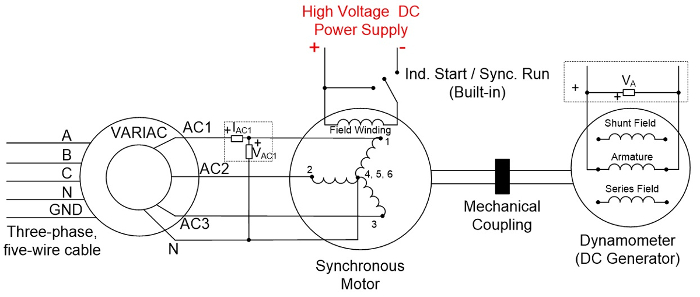
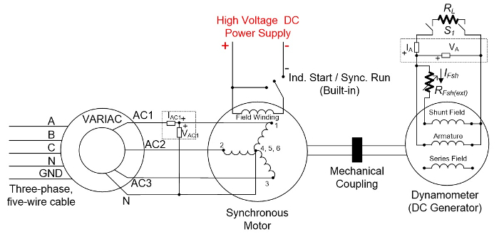
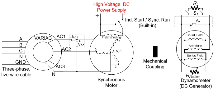
2. 原动力设置和残余磁性
本实验的原动力是同步电机, 它的运行方式是旋转直流发电机转子 (电枢) 的马达。
- 确保三相断开开关、同步电机开关和直流电机开关全部关闭。
- 检查调压器是否在0%。
- 将调压器线连接至三相插座, 并将安装在图5中的设置接通。
- 检查 "启动/运行" 开关是否处于 "开始" 位置。
- 打开三相断开开关。
- 打开高压直流电源。
Results
Application and Summary
Tags
跳至...
此集合中的视频:

Now Playing
直流电机
Electrical Engineering
23.5K Views

电气安全预防措施和基本设备
Electrical Engineering
144.8K Views

磁性元件的特性
Electrical Engineering
15.1K Views

电源杆板介绍
Electrical Engineering
12.5K Views

dc/dc 升压转换器
Electrical Engineering
57.1K Views

dc/dc 降压转换器
Electrical Engineering
21.2K Views

反激式转换器
Electrical Engineering
13.3K Views

单相变压器
Electrical Engineering
20.2K Views

单相整流器
Electrical Engineering
23.6K Views

晶闸管整流
Electrical Engineering
17.6K Views

单相逆变器
Electrical Engineering
18.0K Views

交流异步电动机特性
Electrical Engineering
11.7K Views

变频调速交流感应电机
Electrical Engineering
7.0K Views

交流同步机同步
Electrical Engineering
21.6K Views

交流同步电机特性
Electrical Engineering
14.3K Views
版权所属 © 2025 MyJoVE 公司版权所有,本公司不涉及任何医疗业务和医疗服务。