JoVE Logo

Zaloguj się

DC Motors

Przegląd

Source: Ali Bazzi, Department of Electrical Engineering, University of Connecticut, Storrs, CT.

The DC machine operates with DC currents and voltages as opposed to an AC machine, which requires AC currents and voltages. DC machines were the first to be invented and utilize two magnetic fields that are controlled by DC currents. The same machine can be easily reconfigured to be a motor or generator if appropriate field excitation is available, since the DC machine has two fields termed field and armature. The field is usually on the stator side and the armature is on the rotor side (opposite or inside-out compared to AC machines). Field excitation can be provided by permanent magnets or a winding (coil). When current is applied to the armature or rotor coil, it passes from the DC source to the coil through brushes that are stationary and slip rings mounted on the rotating rotor touching the brushes. When the rotor armature coil is a current-carrying loop, and is exposed to an external field from the stator or field magnet, a force is exerted on the loop. Since the loop is "hanging" on both sides of the motor using bearings, the force produces a torque that will rotate the rotor's shaft rather than move it in any other direction.

This rotation causes the magnetic fields to align but at the same time, slip rings switch sides on the brushes, or "commute," and this is what is known as the commutation process. When this commutation occurs, current flow in the rotor coil is reversed and magnetic fields oppose each other again, causing further torque in the same direction of rotation. This process continues and the rotor shaft spins providing motor action. In generator operation, mechanical rotation is provided to the rotor shaft and current flows out of the rotor after it is induced due to a moving coil under a magnetic field.

The machines discussed in this experiment have a field winding rather than permanent magnets. A commutation process that is critical in DC machine operation uses slip rings and brushes to transfer energy from the rotor (armature) to the outside world since the rotor is spinning and having spinning wires would twist and break them. However, these brushes and slip rings have major reliability drawbacks as they require regular maintenance, brush replacement, cleaning, and may cause sparking. This has led to replacement of most DC machines by AC machines that do not have these issues, and remaining DC machines mostly have permanent magnet field excitation, such as in toys and simple low-power tools. AC machines termed brushless DC machines (or BLDCs) are AC machines that utilize a DC source and power electronic inverter to get AC voltages out of the inverter.

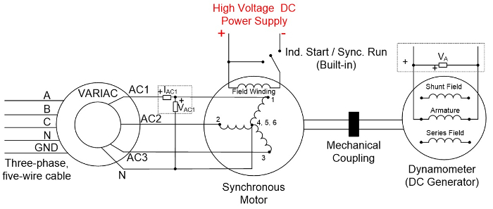
The objective of this experiment is to test two main DC machine configurations: shunt and series. Tests are intended to estimate the residual flux in the machine and to study the no-load and loading characteristics of different configurations.

Zasady

Four main configurations of DC machines exist: separately excited, shunt, series, and compound. These configurations are classified based on the location of the field excitation, where the field is one of the magnetic fields necessary to operate the machine as a motor or generator. Since the field winding is powered by a DC source, that source can be the same as the one powering the DC motor's armature, or can be separate. When separate, the machine is termed "separately excited," and when not, the location of the field winding in the motor's circuit determines what type of configuration it is. If the field winding is placed in parallel with the armature winding to see the same voltage source powering the armature, the machine is in the parallel or shunt configuration.

If the field winding is in series with the armature winding so they have the same current flow, the machine is in the series configuration. If both windings are available, i.e. shunt and series windings are used, then the machine is in the compound configuration. The separately excited configuration is independent from the armature and can be regulated to support various load through automatic control. However, shunt, series, and compound configurations draw current from the same armature source and are therefore affected by the load and armature voltage variations.

With no field excitation, residual magnetism due to the residual magnetic field (λR) in the machine acts as a source for minor field excitation. This can be expressed as an additional term in the back e.m.f. (EA) equation "λRω" which is added to "KIFω" where ω is the mechanical speed of the machine. For a compound DC machine, EA is thus,

EA= KshIFshω+ KseIFseω+ λRω, (1)

where "se" stands for series, "sh" stands for shunt, and K terms are field constants that relate field current and mechanical speed to the back e.m.f. Remember that K values are constant until a saturation limit is reached, after which EA saturates to a certain value.

Ideally, λR is assumed to be zero, but this is not realistic. In order to determine λR, a DC machine is run as a generator without shunt or series excitation and at no load. Thus, the terminal voltage measured VA=EA. If ω is measured, λR can be determined. EA is a characteristic voltage of DC machines, a voltage that counters the armature voltage to limit the current into the machine. In motor operation, the EA is less than the armature voltage, and the higher EA leads to less armature current draw. It is dependent on the shaft speed as shown in Equation 1, and therefore having a higher EA causes higher speed operation. In generator applications, EA is the induced voltage from rotating one magnetic field on the armature vs. the field.

For a shunt machine, Equation 1 still holds, but IFse is set to zero; for a series machine, Equation 1 still holds, but IFsh is set to zero. Compound machines have both shunt and series connected and can be in long- or short-form. When both fields exist, their effect can add up or oppose each other as seen by the armature, and these configurations are termed cumulative or differential. These configurations can be achieved by varying the location of the shunt field before or after the series field, and by having the field currents enter or leave their respective dots. Fig. 1-4 show all four configurations.

Figure 1
Figure 1: A schematic of a cumulative long compound configuration.

Figure 2
Figure 2: A schematic of a cumulative short compound configuration.

Figure 3
Figure 3: A schematic of a differential long compound configuration.

Figure 4
Figure 4: A schematic of a differential short compound configuration.

The goal of this experiment is to compare current, voltage and load relationships in series and shunt configured DC motors. Since only one high power DC power supply is available in this demonstration, separately excited operation is not covered. For shunt and series configurations, the prime mover of the DC generator is a synchronous motor that regulates its speed to 1800 RPM. Any time a DC current measurement is needed, such as IA or IFsh, use the digital multi-meter in current mode (make sure the terminals on the multi-meter are in the current configuration).

Procedura

1. DC Tests

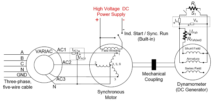
  1. With the low-power DC power supply limited to 0.8 A, connect the supply terminals to the DC machine armature.
  2. Record the supply's DC voltage and current readings.
  3. Estimate the resistance of each winding.
  4. Repeat for the other windings, shunt field and series field, one at a time.
  5. Turn off and disconnect the low-power DC power supply.
  6. Set the built-in field rheostat to maximum resistance and measure its resistance.
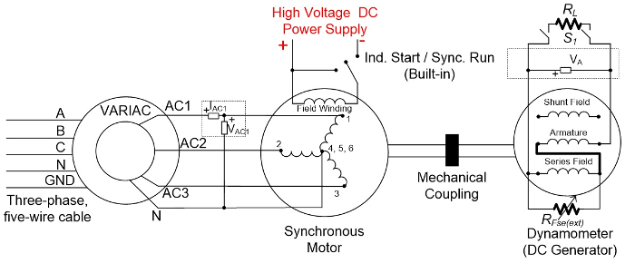
  7. Set the series field rheostat (external) to the maximum resistance and measure its resistance.

2. Prime-Mover Setup and Residual Magnetism

The prime-mover in this experiment is the synchronous machine, which operates as a motor that spins the DC generator rotor (armature).

  1. Make sure the three-phase disconnect switch, synchronous motor switch, and DC motor switch are all off.
  2. Check that the VARIAC is at 0%.
  3. Wire the VARIAC to the three-phase outlet, and connect the setup shown in Fig. 5.
  4. Check that the "Start/Run" switch is in the "Start" position.
  5. Turn on the three-phase disconnect switch.
  6. Turn on the high-voltage DC power supply.
  7. Make sure all connections are clear from the supply terminals.
  8. Press the "V/I DIS" button on the supply to display the voltage and current operating points. Adjust the voltage knob to 125 V.
    1. Do not press the start button.
  9. Press the "Start" button on the DC power supply panel.
  10. Slowly increase the VARIAC output until VAC1 reads 120 V.
  11. When the synchronous motor reaches a steady-state speed, flip the Start/Run switch into the Run position.
  12. Measure and record the rotational speed using the strobe light and record VA.
  13. Turn off the DC power supply and return the VARIAC to 0%.
  14. Reset the "Start/Run" switch to "Start."
  15. Turn off the three-phase disconnect switch.

Figure 5
Figure 5: A schematic of how to setup the prime-mover. Please click here to view a larger version of this figure.

3. DC Shunt Generator Characterization

  1. On the DC generator side, connect the shunt field in parallel with the armature field as shown in Fig. 6.
  2. Use the built-in rheostat for RFsh(ext), and use the multi-meter as an ammeter to measure IFsh.
  3. Keep "S1" open for a no-load test.
  4. Keep "RFsh(ext)" at maximum resistance.
  5. Turn on the three-phase disconnect switch.
  6. Press the "Start" button on the DC power supply panel.
  7. Slowly increase the VARIAC output until VAC1 reads 120 V.
  8. When the synchronous motor reaches a steady-state speed, flip the "Start/Run" switch into the "Run" position.
  9. Measure the shaft speed using the strobe-light technique described elsewhere.
  10. Record VA at this no-load condition on the DC generator side.
  11. Reduce RFsh(ext) until the voltage generated at VA is around 150 V.
  12. After that point, reduce "RFsh(ext)" in five almost-equal steps until the minimum resistance is reached.
    1. For each step, measure VA and IFsh.
  13. Leave RFsh(ext) at its minimum value.
  14. Turn off the DC power supply.
  15. Reduce the VARIAC output to 0%.
  16. Move the ammeter from measuring IFsh to measure IA.
  17. Restart the setup as described earlier.
  18. Set RL to 300 Ω, and turn on "S1". Measure VA and IA.
  19. Turn off "S1," set RL to 200 Ω, then turn on "S1." Measure VA, and IA.
  20. Turn off "S1," set RL to 100 Ω, then turn on "S1." Measure VA, and IA.
  21. Turn off the DC power supply and set the VARIAC output to 0%.
  22. Keep the synchronous generator side of the setup intact.
  23. Disconnect the DC generator connections.
  24. Reset the "Start/Run" switch to "Start."
  25. Turn off the three-phase disconnect switch.

Figure 6
Figure 6: A schematic of the shunt DC generator setup. Please click here to view a larger version of this figure.

4. DC Series Generator Characterization

  1. On the DC generator side, connect the series field in series with the armature field as shown in Fig 7.
    1. Use the external rheostat for RFse(ext).
    2. Use the built-in rheostat as RL and have it at maximum resistance.
    3. Keep "S1" open for a no-load test.
    4. Keep RFse(ext) at maximum resistance.
  2. Turn on the three-phase disconnect switch.
  3. Press the "Start" button on the DC power supply panel.
  4. Slowly increase the VARIAC output until VAC1 reads 120 V.
  5. When the synchronous motor reaches a steady-state speed, flip the "Start/Run" switch into the "Run" position.
    1. Measure VA at this no-load condition on the DC generator side.
  6. Turn on "S1" and reduce RFse(ext) as needed to see non-zero VA.
  7. Vary RL in five almost-equal steps until its 50% setting is reached, set to 300 Ω, and turn on "S1." Measure the speed, VA, and IA.
    1. Turn off "S1," set RL to 200 Ω, then turn on "S1." Measure the speed, VA, and IA.
    2. Turn off "S1," set RL to 100 Ω, then turn on "S1." Measure the speed, VA, and IA.
  8. Turn off the DC power supply.
    1. Set the VARIAC output to 0%.
    2. Keep the synchronous generator side of the setup intact.
    3. Disconnect the DC generator connections.
    4. Reset the "Start/Run" switch to "Start."
  9. Turn off the three-phase disconnect switch.
  10. Disassemble all wires and meters.

Figure 7
Figure 7: A schematic of the series DC generator setup. Please click here to view a larger version of this figure.

<

Wyniki

Series windings typically carry high current rated at the machine's rated armature current, since both series and armature windings are in series. Therefore, series windings are expected to be on the order of a mΩ to a few Ω. Shunt windings on the other hand should draw minimum current from the source which power them along with the machine's armature, and therefore, have large resistance values of tens to hundreds or even thousands of Ω.

The residual λR can be estimated by measuring the armature voltage at no load. Since this a no-load condition, the back e.m.f. and armature voltage are the same, and the back e.m.f. (EA) is a function of λR such that EA=If λRωm where Iis the field current and ωm is the mechanical speed.

Each type of machine has its own voltage-current or torque-speed curve. The advantage of shunt generators is that they can provide voltage without having any load up to full load, while series generators are characterized by not being able to provide any voltage unless there is some load.

Wniosek i Podsumowanie

DC machines are significantly less common than they used to be before the invention of AC induction and synchronous machines. They remain common in simple low power applications such as toys, small robots, and legacy equipment. Permanent magnet DC machines, which use abundant non-rare-earth magnets, are more common than their shunt and series counter parts due to simpler excitation, especially in low cost and low complexity applications.

Tagi

DC MotorsDrive EquipmentElectromechanical MachinesInner Conductive CoilArmatureOuter MagnetStatorDC SourceCommutator SlipperingElectromagnetic ForceTorque FluctuationsMultiple WindingsCommutatorPower SupplyMagnetic FieldsDC Motor ConfigurationsMeasurement Of DC Motor Performance CharacteristicsSpeedCurrentVoltageLoadPermanent Magnet StatersConductor WindingsElectric Field DesignElectro Motor Force EMFTorque Output

Przejdź do...

0:06

Overview

1:18

Principles of DC Motors

3:18

DC Tests

4:24

Measurement of Residual Magnetism

7:26

Applications

9:09

Summary

Filmy z tej kolekcji:

article

Now Playing

DC Motors

Electrical Engineering

23.4K Wyświetleń

article

Electrical Safety Precautions and Basic Equipment

Electrical Engineering

144.6K Wyświetleń

article

Characterization of Magnetic Components

Electrical Engineering

15.0K Wyświetleń

article

Introduction to the Power Pole Board

Electrical Engineering

12.4K Wyświetleń

article

DC/DC Boost Converter

Electrical Engineering

56.9K Wyświetleń

article

DC/DC Buck Converter

Electrical Engineering

21.1K Wyświetleń

article

Flyback Converter

Electrical Engineering

13.2K Wyświetleń

article

Single Phase Transformers

Electrical Engineering

20.2K Wyświetleń

article

Single Phase Rectifiers

Electrical Engineering

23.4K Wyświetleń

article

Thyristor Rectifier

Electrical Engineering

17.5K Wyświetleń

article

Single Phase Inverter

Electrical Engineering

17.9K Wyświetleń

article

AC Induction Motor Characterization

Electrical Engineering

11.6K Wyświetleń

article

VFD-fed AC Induction Machine

Electrical Engineering

6.9K Wyświetleń

article

AC Synchronous Machine Synchronization

Electrical Engineering

21.6K Wyświetleń

article

AC Synchronous Machine Characterization

Electrical Engineering

14.3K Wyświetleń

JoVE Logo

Prywatność

Warunki Korzystania

Zasady

Badania

Edukacja

O JoVE

Copyright © 2025 MyJoVE Corporation. Wszelkie prawa zastrzeżone