フィンドチューブ熱交換器の熱伝達効率のテスト
概要
出典:マイケル・G・ベントンとケリー・M・ドゥーリー、ルイジアナ州立大学化学工学科、バトンルージュ、ロサンゼルス
熱交換器は、ある流体から別の流体に熱を伝達します。異なるニーズを満たすために熱交換器の複数のクラスが存在します。最も一般的なタイプのいくつかは、シェルとチューブ交換器とプレート交換器1です。シェルおよびチューブ熱交換器は、流体が流れるチューブのシステムを使用します。チューブの1セットには冷却または加熱する液体が含まれ、2番目のセットには熱を吸収するか1を伝達する液体が含まれます。プレート熱交換器は、プレートが流れる液体のための各間の小さなギャップと密接に結合されている同様の概念を使用しています。プレート間を流れる流体は、熱と低温の間で交互に、熱が必要な流れ1に出入りするようにする。これらの交換器は表面積が大きいため、通常は1より効率的です。
この実験の目的は、フィン管熱交換器の熱伝達効率をテストし(図1)、フィンのない熱交換器の理論効率と比較することです。実験データは、モノエチレングリコール(MEG)の3つの異なる流量について測定されます。MEG流量ごとに2つの異なる水流量が使用されます。ウィルソンプロット法を使用して、熱伝達係数は実験データから決定されます。さらに、レイノルドの数と転送される熱量は、熱伝達効率を評価するためにフィンの有無にかかわらず流れと比較されます。

図1:フィンドチューブ熱交換器1)MEG出口温度2)水入口温度3)MEG入口温度4)水出口温度5)水量計6)MEG蓄積視力ガラス/シリンダー。
原則
熱交換器は、2つ以上の流体間で熱を伝達します。交換器は、熱を提供している対流とは別の空間で流れる流体種を使用します。フィンは、転写に使用できる表面積を増やすため、より熱伝達を容易にするために流れ領域に追加できます。フィンを追加すると、種が流れる領域が減少し、境界レイヤーが形成できるサーフェスが増え、乱流が少なくなります。流れの乱流が少ないほど、境界層が大きくなります。境界層は熱伝達を阻害するので、乱流が少ないと熱が伝達されなくなる。境界層が層状の場合、混合はほとんどありません。
熱が流れる領域と熱伝達係数の関係は、転送される合計熱の計算に使用されます。この関係は、方程式 1 を使用して計算されます。
 (1)
(1)
ここでQは熱伝達(Btu/hr)、Uは全体的な熱伝達係数、Aは熱が伝達される面積(ft2)、ΔT LMは対数平均温度差である。
全体的な熱伝達係数方程式は次のとおりです。
 (2)
(2)
ここで、aは裸の内管の表面積、Afはフィンの表面積、ALMは対数平均面積差、Aはパイプの表面積(o=外側、i=内側)、配管のΔx厚さ、kはパイプの熱伝導率、h=個別熱伝達係数である。(o=外側、i=内側)
ウィルソンプロット法は、実験データを使用してMEGフロー上の典型的なエネルギーバランスからUoAoを見つけ、その逆を内側パイプの1/Re0.8にプロットします。直線をフィットさせ、熱伝達係数に関連し、上記の式の右側の最初の2つの用語で説明されているy切片を見つけることによって。典型的な縦長方形プロファイルフィン効率方程式は、目的関数の平方和を最小化することによって熱伝達係数とフィン効率を解く2番目の方程式として使用されます。この方法は、水流量が異なるMEG流路条件に適用されます。
熱伝達係数を計算するには、次の式で指定するレイノルズ数を使用します。
 (3)
(3)
ここで、G は流体の質量速度、D は流体が流れるパイプの直径(Deq、同等の直径は計算のために D をフィンに置き換えます)、μ は流体の粘度です。縦長方形プロファイルフィンのフィン効率方程式は次のとおりです。
 (4)
(4)
ここで、m は √(2h/kt)、h は熱伝達係数、k はパイプの熱伝導率、t はフィンの厚さ、b はフィンの高さです。
手順
1. 開始および流量決定
- 蒸気発生器の下にある充電バルブを開きます。
- ユニットを起動し、蒸気が形成を開始するために15分を許可します。
- 水の流量を計算する
- ストップウォッチを開始し、水の体積を表示するゲージを監視します。
- 30sの後に時計を停止し、ゲージに表示される水の総量を記録します。
- 体積流量を時間で割って体積流量を決定します。
- 流量計からのMEG流量を記録します。
- 熱電対から温度を観察し、値を記録します。
2. 流量の変化とシャットダウン
- 6 つの異なる実行のデータを収集するには、水の流量を高流量または低流量に設定し、MEG の高、中、または低流量で実行します。
- 参考までに、MEG の低、中、高流量に対して、0.0439、0.0881、および 0.1323 gal/秒が使用されています。
- 前に、各ランの熱電対の体積流量と温度差を記録します。
- 完了したら、楽器をシャットダウンします。
- バルブを閉じて、蒸気、モノエチレングリコール、水の流れを止めます。
- メインスイッチをオフにします。
3. 計算
- 式1を使用して、熱電対(温度測定に使用されるデバイス)と熱交換器の既知の物理的寸法(操作対象ユニットのユーザーマニュアルに記載されている)から読み取られた温度差を使用して、転送された総熱量Qを計算します。).温度差は、各実行の温度測定値から取得できます。
- 一意の試運転ごとに転送される熱を計算し、ウィルソンプロット法を使用して3つのMEG流量の熱伝達係数を求めます。
- 計算された熱伝達とレイノルズ数をフィンのない熱交換器の理論値と比較します。
結果
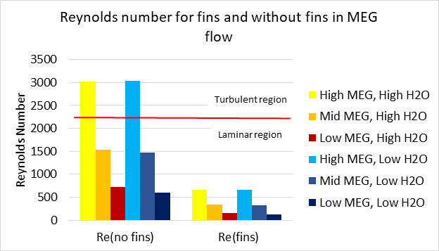
フィンドチューブ熱交換器が乱流に達しませんでした(図2)。フィンは、層流および乱流理論を通じて知られている境界層が形成される追加のサーフェスを提供します。流体が十分な速度でない場合、流体は乱流に到達しません。フィン間の境界層は層領域で重なり合うので、流体は層状のままです。

図2:各設定のレイノルズ数
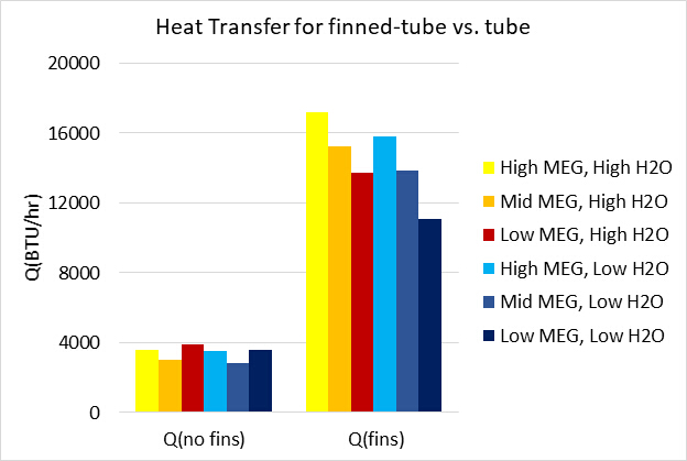
MEGの異なる流量でフィンの有無にかかわらずチューブ内で伝達される熱量、Q(図3)。結果は、フィンチューブが同じ動作条件でフィンのないチューブよりも多くの熱を伝達することを示しています。この実験では、フィンは明らかに熱伝達を改善した。これは、より大きな表面積がある場合に熱伝達がより効果的であるためです。フィンチューブ熱交換器は、レイノルズ数が低いにもかかわらず、より多くの熱を伝達しました(図3)。

図3:各流量でフィンの有無にかかわらず交換器間で熱を伝達する。
申請書と概要
熱交換器は、農業、化学生産、HVACなど様々な産業で使用されています。この実験の目的は、フィン管熱交換器の熱伝達効率をテストし、フィンのない熱交換器の理論効率と比較する点でした。実験データは、使用されるMEG流量ごとにモノエチレングリコール(MEG)の3つの異なる流量と2つの固有の水流量について測定した。Reynoldの数はフィンの有無にかかわらず流れを決定し、各ユニークな試運転の熱伝達係数、表面積、フィン効率を計算するために使用されました。このデータは、フィンなしで乱流が可能かどうか、およびどの試験条件の下で最も熱伝達が発生するかを評価するために使用されました。フィンドチューブは乱流に達しなかった。その結果、熱交換器を通るMEGの流れが乱流に達しないため、フィンチューブは同じ動作条件でフィンのないチューブよりも多くの熱を伝達する。
農業業界では、熱交換器は、砂糖およびエタノール2の処理に使用されます。これらの製品は両方ともジュースに加工され、さらに処理するために加熱する必要があります2.熱交換器は、2を明確にするためにジュースを加熱するために使用される。ジュースが偶数シロップに処理されると、さらに交換器による加熱は、処理を継続し、糖蜜2を形成する必要がある。糖蜜は熱交換器を使用して冷却され、その後、後で処理するために保存することができます2.
暖房、換気、および空調システムは、HVACとして知られており、すべて熱交換器3を利用しています。家庭用空調・暖房ユニットは、熱交換器3を利用しています。より大きな設定では、化学プラント、病院、および輸送センターはすべて、はるかに大きなスケール3で、同様の熱交換器HVACを利用しています。化学工業では、熱交換器は、多種多様なプロセス4を加熱および冷却するために使用される。発酵、蒸留、断片化はすべて熱交換器4を利用する。整流および精製のようなさらに多くのプロセスは熱交換器4を必要とする。
参考文献
- Types of Heat Exchangers." Types of Heat Exchangers. N.p., n.d. Web. 19 Jan. 2017.
- Heat exchangers for sugar factories and distilleries." Heat exchanger for sugar and ethanol industry. N.p., n.d. Web. 19 Jan. 2017.
- Biotechnology and green chemistry heat exchangers." Heat exchanger for green chemical industry. N.p., n.d. Web. 19 Jan. 2017.
- Heat exchangers for heating and cooling." Heat exchangers for district heating, cooling and HVAC. N.p., n.d. Web. 19 Jan. 2017.
タグ
スキップ先...
このコレクションのビデオ:

Now Playing
フィンドチューブ熱交換器の熱伝達効率のテスト
Chemical Engineering
17.9K 閲覧数

トレイを使用して対流および伝導性の熱伝達を調査するドライヤー
Chemical Engineering
44.0K 閲覧数

プロピレング リコール溶液の粘度
Chemical Engineering
32.9K 閲覧数

シリカ アルミナ粉末のポロシ メーター
Chemical Engineering
9.6K 閲覧数

押し出しによる力法律モデルのデモ
Chemical Engineering
10.1K 閲覧数

ガス吸収
Chemical Engineering
36.8K 閲覧数

気液平衡
Chemical Engineering
89.2K 閲覧数

トレイ蒸留効率に還流比の影響
Chemical Engineering
77.8K 閲覧数

液-液抽出の効率
Chemical Engineering
48.5K 閲覧数

液相反応: しょ糖
Chemical Engineering
9.7K 閲覧数

化学修飾によるサリチル酸の結晶化
Chemical Engineering
24.3K 閲覧数

充填層反応器内の単相および流れ
Chemical Engineering
19.0K 閲覧数

ポリジメチルシロキサンを付加重合の動力学
Chemical Engineering
16.1K 閲覧数

エチレンの触媒反応: 水素化
Chemical Engineering
30.4K 閲覧数

スピンと寒さ
Chemical Engineering
7.4K 閲覧数
Copyright © 2023 MyJoVE Corporation. All rights reserved