
JoVE 비디오를 활용하시려면 도서관을 통한 기관 구독이 필요합니다. 전체 비디오를 보시려면 로그인하거나 무료 트라이얼을 시작하세요.
Method Article
실리카 초고 품질 팩터 Microresonators의 제작
요약
우리는 자유 서 microspheres 및 온칩 microtoroids 포함한 실리카 공진 충치를 조작하는 이산화탄소 레이저 reflow 기법의 사용을 설명합니다. reflow 메서드는 두 장치 사이 긴 광자 수명 있도록, 표면 결함을 제거합니다. 그 결과 디바이스는 통신에서 biodetection에 이르기까지 애플 리케이션을 가능하게, 초고 품질 요인이 있습니다.
초록
Whispering gallery resonant cavities confine light in circular orbits at their periphery.1-2 The photon storage lifetime in the cavity, quantified by the quality factor (Q) of the cavity, can be in excess of 500ns for cavities with Q factors above 100 million. As a result of their low material losses, silica microcavities have demonstrated some of the longest photon lifetimes to date1-2. Since a portion of the circulating light extends outside the resonator, these devices can also be used to probe the surroundings. This interaction has enabled numerous experiments in biology, such as single molecule biodetection and antibody-antigen kinetics, as well as discoveries in other fields, such as development of ultra-low-threshold microlasers, characterization of thin films, and cavity quantum electrodynamics studies.3-7
The two primary silica resonant cavity geometries are the microsphere and the microtoroid. Both devices rely on a carbon dioxide laser reflow step to achieve their ultra-high-Q factors (Q>100 million).1-2,8-9 However, there are several notable differences between the two structures. Silica microspheres are free-standing, supported by a single optical fiber, whereas silica microtoroids can be fabricated on a silicon wafer in large arrays using a combination of lithography and etching steps. These differences influence which device is optimal for a given experiment.
Here, we present detailed fabrication protocols for both types of resonant cavities. While the fabrication of microsphere resonant cavities is fairly straightforward, the fabrication of microtoroid resonant cavities requires additional specialized equipment and facilities (cleanroom). Therefore, this additional requirement may also influence which device is selected for a given experiment.
Introduction
An optical resonator efficiently confines light at specific wavelengths, known as the resonant wavelengths of the device. 1-2 The common figure of merit for these optical resonators is the quality factor or Q. This term describes the photon lifetime (τo) within the resonator, which is directly related to the resonator's optical losses. Therefore, an optical resonator with a high Q factor has low optical losses, long photon lifetimes, and very low photon decay rates (1/τo). As a result of the long photon lifetimes, it is possible to build-up extremely large circulating optical field intensities in these devices. This very unique property has allowed these devices to be used as laser sources and integrated biosensors.10
A unique sub-class of resonators is the whispering gallery mode optical microcavity. In these devices, the light is confined in circular orbits at the periphery. Therefore, the field is not completely confined within the device, but evanesces into the environment. Whispering gallery mode optical cavities have demonstrated some of the highest quality factors of any optical resonant cavity to date.9,11 Therefore, these devices are used throughout science and engineering, including in fundamental physics studies and in telecommunications as well as in biodetection experiments. 3-7,12
Optical microcavities can be fabricated from a wide range of materials and in a wide variety of geometries. A few examples include silica and silicon microtoroids, silicon, silicon nitride, and silica microdisks, micropillars, and silica and polymer microrings.13-17 The range in quality factor (Q) varies as dramatically as the geometry. Although both geometry and high Q are important considerations in any field, in many applications, there is far greater leverage in boosting device performance through Q enhancement. Among the numerous options detailed previously, the silica microsphere and the silica microtoroid resonator have achieved some of the highest Q factors to date.1,9 Additionally, as a result of the extremely low optical loss of silica from the visible through the near-IR, both microspheres and microtoroids are able to maintain their Q factors over a wide range of testing wavelengths.18 Finally, because silica is inherently biocompatible, it is routinely used in biodetection experiments.
In addition to high material absorption, there are several other potential loss mechanisms, including surface roughness, radiation loss, and contamination loss.2 Through an optimization of the device size, it is possible to eliminate radiation losses, which arise from poor optical field confinement within the device. Similarly, by storing a device in an appropriately clean environment, contamination of the surface can be minimized. Therefore, in addition to material loss, surface scattering is the primary loss mechanism of concern.2,8
In silica devices, surface scattering is minimized by using a laser reflow technique, which melts the silica through surface tension induced reflow. While spherical optical resonators have been studied for many years, it is only with recent advances in fabrication technologies that researchers been able to fabricate high quality silica optical toroidal microresonators (Q>100 million) on a silicon substrate, thus paving the way for integration with microfluidics.1
The present series of protocols details how to fabricate both silica microsphere and microtoroid resonant cavities. While silica microsphere resonant cavities are well-established, microtoroid resonant cavities were only recently invented.1 As many of the fundamental methods used to fabricate the microsphere are also used in the more complex microtoroid fabrication procedure, by including both in a single protocol it will enable researchers to more easily trouble-shoot their experiments.
프로토콜
1. Microsphere의 제조
- 한쪽에서 광섬유, 스트립 ~ 1.5 "cladding 소량 (약 5 인치)를 선택하고 메탄올 또는 에탄올 (그림 1A, B) 중 하나와 함께 청소.
- 광섬유 칼로 사용할 경우, 다니엘은 끝. 사용할 수없는 경우, 전선 절단기 또는 ~ 0.5 "가 남아있다는 등 가위로 잘라. 광섬유 식칼을 사용하는 장점은 그림 1B와 같이 매우 부드럽고 균일한 커팅을 생산한다는 것입니다. 커팅에서 과도한 거칠기 또는 결함이 원인이 될 수 있습니다 결과 분야의 품질 계수를 낮추 고르지 reflow.
- 대한 ~ 500μm 직경 스폿 크기에 초점을 맞춘 CO 2 레이저 전력 3W로 청소 섬유 끝을 노출 ~ 1 번째 (그림 1C, D, E). 이것은 직경 분야 ~ 200μm을 생산하고 있지만, 크기는 광섬유의 직경을 증가 또는 감소에 의해 조정됩니다. 약간 B는 또한 레이저 강도를 수 조정reflow 크거나 작은 분야에 필요한 전자.
2. Microtoroid 제조
- 디자인하고 원하는 간격과 직경, 어두운, 고체 동그라미로 photomask를 확인하십시오. 그것은 생산 toroids이 마스크에 동그라미보다 25~30% 작아됩니다 것이 중요합니다. 예를 들어, 100 미크론의 직경과 단단한 원형은 약 75 미크론의 직경과 환형를 생성합니다. 또한, 각 동그라미 사이의 공간 5mm 이상의 서클의 배열 사이 마스크의 가장자리 주위에 공간이 최소 1~2mm두고하는 것이 좋습니다. 샘플 웨이퍼를 조심스럽게 핀셋으로 취급되어야하기 때문에, 그것은 toroids을 손상시키지 않고 그립에 핀셋을위한 공간을두고하는 것이 중요합니다. 여분의 공간은 또한 완성된 장치에 두어 빛을 테이퍼 광섬유위한 공간을 제공하고 샘플을보다 쉽게보다 작은 배열로 자른 수 있습니다. 이 절차를 위해, 우리는 160 μm의 디 늘어서있는 마스크를 사용동그라미의 각 행 사이의 공간 ~ 5mm로 떨어져 ameter 서클은 ~ 1mm. 완료 toroids 지름이 약 110 μm의 수 있습니다.
- 열 성장 실리카의 2 μm의 두께 층으로 실리콘 웨이퍼로 시작. 다니엘은 웨이퍼 석판술 마스크에 원하는 microdisk 패턴에 맞게, 포토 레지스트 에지 비드위한 공간을 떠난다. 제조의 시작 부분에서, 그것이 일반적으로 실리콘 웨이퍼의 큰 조각 (~ 몇 cm X 몇 ㎝)에 서클의 에칭 여러 배열에 가장 편리합니다. 더 큰 웨이퍼는 석판술와 시간에 더 많은 샘플 에칭 비오이을 허용하고, 더 쉽게 핀셋으로 처리됩니다. 나중에 XeF이 에칭 단계 전에, 그것은보다 빠르고 균일한 XeF이 에칭을 허용하도록 다니엘 작은 배열에 큰 웨이퍼로 추천합니다.
- fumehood에서, 아세톤, 메탄올, 이소프로판올, 그리고 탈이온수로 rinsing하여 웨이퍼를 깨끗이 닦아주십시오. 샘플 질소 또는 필터링된 검색을 사용하여 건조 불어ressed 공기 총을, 그리고 뜨거운 접시에 넣어 말려 최소한 2 분 동안 120 ° C로 설정합니다.
- 웨이퍼 멋진 해줘서 후 용매 / 가연성 fumehood에 그들을 배치하고 증기 증착 방법을 사용하여 2 분 동안 HMDS에 노출. 간단한 기상 증착 방법 : 작은 10ml를 비커에 HMDS 몇 방울을 넣어 다음 증기를 개최하기 위해 큰 유리 용기와 웨이퍼와 작은 비커를 포괄합니다.
- 적절한 크기의 마운트로 회전자에서 샘플을 놓습니다. dropper 병 또는 주사기 및 필터를 사용하여 샘플에 포토 레지스트를 적용합니다. 3000rpm 45 초 뒤에 500rpm에서 5 초 각 샘플에 코트 S1813 포토 레지스트를 봐. 웨이퍼 엣지 비드가 patterning에 방해가되지 않도록 충분히 큰 경우 에지 비드 제거가 필요하지 않습니다.
- 소프트 베이킹 95에서 뜨거운 접시에 포토 레지스트 ° 2 분을 C #.
- 자외선 마스크 aligner하고 원하는 photomask 사용에 포토 레지스트 덮인 샘플을 폭로하다자외선 방사선 80mJ/cm 2 총.
- 자외선에 노출되었다 포토 레지스트를 제거하는 MF-321 개발에 샘플을 담가. 개발하는 동안 포토 레지스트가 웨이퍼에서 제거하고 용해되기 때문에, 잘 봐. 그것은 포토 레지스트를 균일하게 제거되었는지 확인하기 위해이 과정에서 지속적으로 휙 / 컨테이너를 저어하는 것이 중요합니다. 주어진 매개 변수의 경우 포토 레지스트는 약 30 초 개발 소요됩니다.
- 대부분의 불필요한 레지스트의이 개발자에 녹아되면 물을를 실행하는 아래 철저하게 샘플을 린스, 부드럽게 질소 또는 공기 총을 사용하여 샘플을 건조 불어, 모든 바람직하지 않은 포토 레지스트가 제거되었는지 확인하기 위해 현미경으로 표본을 검사한다. 필요한 경우, 샘플은 개발자에 다시 포장되어 수 있지만, 하나는 원하는 포토 레지스트 패턴도 손상될 수로 샘플을 지나치게 현상하다하지 않도록 주의해야합니다. 원하는 패턴이 손상되거나 결함이있는 경우 (포토 레지스트가 될 수 있습니다아세톤과 같이 2.1-2.9)가 다시 반복 수로 제거.
- 개발 후 깨끗이 물에을 실행에 샘플을 린스, 부드럽게 샘플을 건조 불어 및 하드 110에서 뜨거운 접시에 그들을 만들어 2 분을 ° C에서.에게 이 단계는 개발 과정에서 발생한 포토 레지스트와 부분 보수 거칠기를 reflowing, 자사의 유리 전이 온도 위에 포토 레지스트를 가열.
- 테플론 용기에 필요한 보호 장비를 사용하여 향상된 버퍼 산화물 에칭 (BOE)에 샘플을 담가. 비오이는 실리콘 웨이퍼 (그림 2A-C)에 원형 실리카 패드를 형성하기 위해 포토 레지스트에서 다루지 않은 실리카를 파 놓았 HF를 포함합니다. 향상된 버퍼 HF는 결과 실리카 서클에 부드럽고 에칭, 최소화 거칠기를 만들어냅니다. 그것이 HF는 49% HF로 시작하는 버퍼 혼합하는 것이 가능하지만, 이것은 일반적으로 오직 소량이 만들어 높은 변수 결과를 초래할 수 있습니다.
- 약 15-20분 (D 이후패턴, 샘플 크기와 샘플의 수)에 epending, 테플론 핀셋을 사용하여 BOE에서 샘플을 제거합니다. 조심스럽게 물을를 실행에 샘플을 린스. 샘플 소수성이되면 실리카가 제거되었습니다.
- , 에칭 rinsing 및 샘플을 건조 후 광학 현미경을 사용하여 그들을 검사한다. 원하는 패턴이 완전히 새겨져되어 모든 원치 않는 실리카가 제거되었는지 확인하십시오. 필요한 경우 추가로 에칭을 위해 BOE에 샘플을 반환합니다. 하나는 샘플을 overetch하지 않도록주의해야하거나, 포토 레지스트 밑에있는 원형 패턴이 손상될 수 있습니다.
- 일단 비오이 에칭이 완료 철저하게 탈이온수에서 샘플을 씻어 건조 폭파. 샘플은 실리콘 웨이퍼의 대형 조각에있다면, 그것은 또한 (다이싱의 톱 또는 다이아몬드 학자를 사용하여) 실리카 서클의 개별 행을 가진 작은 조각으로 잘라 것이 좋습니다. 동그라미의 개별 행을 XeF에보다 신속하고 균일하게 새겨져있다이 에칭 단계 (2.16). 절단에 의해 생산된 실리콘 먼지는 다음 단계에서 세척하는 동안 제거됩니다.
- 아세톤, 메탄올, 이소프로판올, 그리고 탈이온수로 rinsing하여 포토 레지스트를 제거하고, 최소한 2 분 동안 120 ° C 핫 플레이트에 질소 총과 난방을 사용하여 샘플을 건조.
- XeF이 식각 장치를 사용하여 실리카 microdisks을 (그림 2D-F) 형성 원형 실리카 패드 아래에 실리콘을 약화. 새겨져 금액 인한 microdisk의 기둥이 같은 광학 현미경으로 검사에 의해 결정되는 총 디스크 직경 약 1/3-1/2가되도록 약 3분의 1 실리카 원의 크기 여야합니다. XeF이 펄스의 수와 각 펄스의 기간은 챔버 및 사용 XeF이 식각 장치의 종류에있는 실리콘의 양에 따라 달라집니다.
- XeF이 에칭 후, 약 1에 초점을 CO 2 레이저 광선에 샘플을 폭로하다~ 3 초 동안이나 매끄러운 환형까지 2W 강도는 (2g-i 명령을 그림) 형성됩니다. 디스크의 정확한 크기와 XeF 2의 양의 가격을 내리다, 약간 높거나 낮은 농도 및 노출 시간에 따라이 microtoroid를 형성하는 데 필요한 수 있습니다. 그것은 실리카 microdisk는 부드럽고 원형 microtoroid를 형성되도록, 레이저 빔을 및 microdisk의 중심의 중심이 정렬됩니다 것이 중요합니다.
3. 대표 결과
microsphere와 microtoroid 장치는 광학 현미경과 주사 전자 현미경 (그림 1D, 전자 및 그림 2 시간, I)를 사용하여 몇 군데하실 수 있습니다. 모든 이미지에 장치 표면의 균일 분명하게 나타난다.
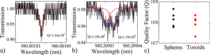
세부적인 접근 방식이 초고-Q 장치를 생성하는지 확인하기 위해서, 우리는 또한 라인폭 (Δλ) 측정을 수행하고 로드된를 계산하여 여러 장치의 Q 계수의 특징Q 간단한 표현에서 : Q = λ / Δλ = ωτ 어디 λ = 공진 파장, ω = 주파수, 그리고 τ = 광자 수명. 이전에 자세한 절차를 1,9와 여러 장치의 비교 그래프를 사용하여 조작 각 장치의 대표 스펙트럼은 그림 3에 표시됩니다. 모든 장치의 품질 요소는 대부분 100,000,000 위에 있기 때문에 위의 10,000,000입니다.
microsphere의 스펙트럼은 빛이 시계 방향 또는 시계 반대 방향으로 전파 광 모드 중 하나에 결합되는 것을 나타내는 하나의 공명했습니다. 그러나, 환형의 스펙트럼이 동시에 시계 방향과 시계 반대 방향으로 모드 모두에 결합하여 그 빛을 나타내는 분할 공진을 전시. 커플링 사이트에서 약간의 결함이있을 경우이 현상이 발생합니다. 듀얼 Lorentzian로 스펙트럼을 맞추함으로써 두 모드의 Q 계수가 결정됩니다. 분할 공진 phenomeNA는 구형과 환형 resonators 모두에서 발생할 수 있지만, 그들은 결점에 더 취약하고 분야에 비해 적은 광학 모드가로서 더 자주 toroids에서 관찰된다.

microsphere 캐비티 가공 과정의 그림 1. 플로우 차트. ) 렌더링 및 세척은 죽습 광섬유의 B) 광학 현미경. C) 렌더링, D) 광학 현미경 및 전자)은 공진기 microspere의 전자 현미경 스캐닝.

microtoroid 캐비티 가공 과정의 그림 2. 플로우 차트. ) 렌더링, B)는 위에서 내려다 보는 광학 현미경과 c)와 같은 석판술 및 비오이 에칭에 의해 정의된 원형 산화 패드의 전자 현미경 스캐닝 측면 볼 수 있습니다. BOE에 의해 형성되는 산화물의 약간 쐐기 모양을합니다. D) 렌더링, 전자) 최고의 전망광학 현미경과 F) XeF이 에칭 단계 후에 산화 패드의 전자 현미경 스캐닝 측면 볼 수 있습니다. 산화물 디스크가 쐐기 모양의 주변을 유지합니다. microtoroid 캐비티의 전자 현미경 스캐닝 G) 렌더링, H) 위에서 내려다 광학 현미경과 내가) 사이드 뷰.

그림 3.) microsphere와 라인폭 측정 방법을 사용하여 결정된 b)는 microtoroid 공진 충치 대표 품질 계수 스펙트럼. 매우 높은 Q 장치에서, 하나는 빛이 작은 결함을 반영하고 시계 방향과 반시계 방향 모두에서 순환하는, 모드-분할 또는 더블 피크를 관찰할 수 있습니다. C) 여러 microsphere와 microtoroid 공진 충치의 Q 요인을 보여주는 비교 그래프. 큰 그림을 보시려면 여기를 클릭하세요 .

그림 4. CO 2 레이저 reflow의 도식 설정. CO 2 레이저 빔 (고체 파란색 라인)을 반영하고 샘플에 초점을 맞추었습니다. 그것은 10.6 μm의 / 10.6 μm의을 전달하고 633 nm의를 반영하는 633 nm의 빔을 결합기를 통해 전달합니다. 빔 결합기의 오프 샘플의 광학 열 이미지를 반사하므로 이미지가 다소 빨간색입니다. 이 설치에 필요한 부품의 목록은 표 4에 있습니다.

그림 5. 잘못) microsphere와 b) microtoroid 공진 충치 reflowed. 빔 내에서 잘못된 위치로 인해 장치 '말 구성된 것입니다. C) 가난한 photomask이나 가난한 리소그래피의 결과, 환형은 달 모양입니다.
토론
모든 광학 구조와 마찬가지로 제조 공정의 모든 단계에서 청결을 유지하는 것은 매우 중요합니다. 리소그래피와 제조의 주제에 쓰여진 수많은 교과서가있는 바와 같이, 아래 제안은 종합 있겠지만 연구자들이 직면보다 일반적인 문제 몇 가지를 강조하기위한 것이 아닙니다. 19-20
microtoroid의 주변의 균일도가 초기 디스크의 균일에 의해 결정되기 때문에 패턴이 매우 ...
공개
관심의 어떠한 충돌 선언 없습니다.
감사의 말
A. 메이커는 Annenberg 재단 대학원 연구 원정대에 의해 지원되고,이 작품은 국립 과학 재단 [085281과 1028440]에 의해 지원되었다.
자료
| Name | Company | Catalog Number | Comments |
| 부분의 이름 | 회사 | 카탈로그 번호 | 댓글 |
| 섬유 학자 | 뉴 포트 | F-RFS | 선택 |
| 광학 섬유 | 뉴 포트 | F-SMF-28 | 광섬유의 유형은 사용할 수 있습니다. |
| 섬유 코팅 리퍼 | 뉴 포트 | F-STR-175 | 와이어 스트리퍼는 사용할 수 |
| 에탄올 | 모든 벤더 | 솔벤트 수준의 순도 | 메탄올이나 이소프로판올는 대체 위치 |
표 1. Microsphere 제조 재료.
| 시약의 이름 | 회사 | <강한> 카탈로그 번호 | 댓글 |
| 2μm 열 성장 규소와 실리콘 웨이퍼 | WRS 자료 | N / A | 우리 고유 8 일 <100>, 4 "직경을 사용 |
| HMDS (헥사메틸디실아젠) | 올드 리치 | 440,191 | |
| 포토 레지스트 | 쉬플리 | S1813 | |
| 개발자 | 쉬플리 | MF-321 | |
| 개선 - HF 버퍼 | Transene | N / A | 향상된 버퍼 HF는 일반 비오이 또는 HF보다 에칭 부드럽고 더 나은 품질을 제공합니다 |
| 아세톤, 메탄올, 이소프로판올 | 모든 벤더 | 99.8 %의 순도 |
표 2. Microtoroid 제작 재료.
| 장비 이름 | 제조 | 카탈로그 번호 | 댓글 |
| 스피너 | Solitec | 5110-ND | 모든 회전자 사용할 수 있습니다. |
| Aligner | 조사할 Microtec | MJB 3 | 모든 aligner 사용할 수 있습니다. |
| XeF이 에칭 | 고급 통신 기기 주식 회사 | # ADCETCH2007 |
표 3. Microtoroid 제조 장비.
| 부분의 이름 | 회사 | 카탈로그 번호 | 댓글 |
| CO 2 를 레이저 | Synrad | 시리즈 48 | |
| 3 축 스테이지 | OptoSigma | 120-0770 | 뿐만 아니라 다른 업체에서 사용할 수 있습니다. |
| 시 리플렉터 1 "직경) | II-VI | 308,325 | 뿐만 아니라 다른 업체에서 사용할 수 있습니다. |
| 운동학 짐벌 마운트 (SI 반사기의 경우) | 토르 실험실 | KX1G | 뿐만 아니라 다른 업체에서 사용할 수 있습니다. |
| 빔 조합기 (1 "직경) | Meller 광학 | L19100008-B0 | 뿐만 아니라 다른 업체에서 사용할 수 있습니다. |
| 4 "초점 거리 렌즈 (1"직경) | Meller 광학 또는 II-VI | 다른 업체에서 제공뿐만 아니라 | |
| 모듬 게시물, 렌즈 마운트 | 토르 연구소, 뉴 포트, 에드먼드 광학 또는 Optosigma | ||
| 줌 6000 머신 비전 시스템 | Navitar | N / A | 실시간 영상에 대한 일반적인 USB 카메라와 컴퓨터가 필요합니다. 이 키트로 구입하고 있습니다. |
| 줌 6000 시스템 Focuser | 에드먼드 광학 | 54-792 | 뿐만 아니라 다른 업체에서 사용할 수 있습니다. |
| 줌 6000에 대한 XZ의 축 Positioners | 파커 천변 만화의 | CR4457, CR4452, 4499 | CR4457은 X 축이며, CR4452은 Z 축이며, 4499은 브라켓을 장착하고 있습니다. |
표 4. CO 2 레이저 Reflow 설정.
참고문헌
- Armani, D. K., Kippenberg, T. J., Spillane, S. M., Vahala, K. J. Ultra-high-Q toroid microcavity on a chip. Nature. 421, 925-928 (2003).
- Gorodetsky, M. L., Savchenkov, A. A., Ilchenko, V. S. Ultimate Q of optical microsphere resonators. Optics Letters. 21, 453-455 (1996).
- Armani, A. M., Kulkarni, R. P., Fraser, S. E., Flagan, R. C., Vahala, K. J. Label-Free, Single-Molecule Detection with Optical Microcavities. Science. 317, 783 (2007).
- Choi, H. S., Ismail, S., Armani, A. M. Studying polymer thin films with hybrid optical microcavities. Optics Letters. 36, 2152-2154 (2011).
- Aoki, T. Observation of strong coupling between one atom and a monolithic microresonator. Nature. 443, 671-674 (2006).
- Hsu, H. -. S., Cai, C., Armani, A. M. Ultra-low threshold Er:Yb sol-gel microlaser on silicon. Optics Express. 17, 23265 (2009).
- Zhu, J. On-chip single nanoparticle detection and sizing by mode splitting in an ultrahigh-Q microresonator. Nature Photonics. 4, 46-49 (2009).
- Zhang, X., Choi, H. -. S., Armani, A. M. Ultimate quality factor of silica microtoroid resonant cavities. Applied Physics Letters. 96, 153304 (2010).
- Vernooy, D. W., Ilchenko, V. S., Mabuchi, H., Streed, E. W., Kimble, H. J. High-Q measurements of fused-silica microspheres in the near infrared. Optics Letters. 23, 247-249 (1998).
- Saleh, B. E. A., Teich, M. C. . Fundamentals of Photonics. , (2007).
- Ilchenko, V. S. Crystal quartz optical whispering-gallery resonators. Optics Letters. 33, 1569-1571 (2008).
- Soteropulos, C., Hunt, H., Armani, A. M. Determination of binding kinetics using whispering gallery mode microcavities. Applied Physics Letters. 99, 103703 (2011).
- Barclay, P. E., Srinivasan, K., Painter, O., Lev, B., Mabuchi, H. Integration of fiber-coupled high-Q SiNx microdisks with atom chips. Applied Physics Letters. 89, (2006).
- Srinivasan, K., Painter, O. Mode coupling and cavity-quantum-dot interactions in a fiber-coupled microdisk cavity. Physical Review. A. 75, (2007).
- Xu, Q. F., Lipson, M. All-optical logic based on silicon micro-ring resonators. Optics Express. 15, 924-929 (2007).
- Martin, A. L., Armani, D. K., Yang, L., Vahala, K. J. Replica-molded high-Q polymer microresonators. Optics Letters. 29, 533-535 (2004).
- Chao, C. Y., Guo, L. J. Polymer microring resonators fabricated by nanoimprint technique. Journal of Vacuum Science Technology B. 20, 2862-2866 (2002).
- Armani, A. M., Armani, D. K., Min, B., Vahala, K. J., Spillane, S. M. Ultra-high-Q microcavity operation in H2O and D2O. Applied Physics Letters. 87, 151118 (2005).
- Kovacs, G. T. A. . Micromachined Transducers Sourcebook. , (1998).
- Kovacs, G. T. A., Maluf, N. I., Petersen, K. E. Bulk Micromaching of Silicon. Proceedings of the IEEE. 86, 1536-1551 (1998).
재인쇄 및 허가
JoVE'article의 텍스트 или 그림을 다시 사용하시려면 허가 살펴보기
허가 살펴보기더 많은 기사 탐색
This article has been published
Video Coming Soon
Copyright © 2025 MyJoVE Corporation. 판권 소유