Method Article
Method for Recording Broadband High Resolution Emission Spectra of Laboratory Lightning Arcs
In This Article
Summary
Emission spectroscopy techniques have traditionally been used to analyze inherently random lightning arcs occurring in nature. In this paper, a method developed to obtain the emission spectroscopy from reproducible lightning arcs generated within a laboratory environment is described.
Abstract
Lightning is one of the most common and destructive forces in nature and has long been studied using spectroscopic techniques, first with traditional camera film methods and then digital camera technology, from which several important characteristics have been derived. However, such work has always been limited due to the inherently random and non-repeatable nature of natural lightning events in the field. Recent developments in lightning test facilities now allow the reproducible generation of lightning arcs within controlled laboratory environments, providing a test bed for the development of new sensors and diagnostic techniques to understand lightning mechanisms better. One such technique is a spectroscopic system using digital camera technology capable of identifying the chemical elements with which the lightning arc interacts, with these data then being used to derive further characteristics. In this paper, the spectroscopic system is used to obtain the emission spectrum from a 100 kA peak, 100 µs duration lightning arc generated across a pair of hemispherical tungsten electrodes separated by a small air gap. To maintain a spectral resolution of less than 1 nm, several individual spectra were recorded across discrete wavelength ranges, averaged, stitched, and corrected to produce a final composite spectrum in the 450 nm (blue light) to 890 nm (near infrared light) range. Characteristic peaks within the data were then compared to an established publicly available database to identify the chemical element interactions. This method is readily applicable to a variety of other light emitting events, such as fast electrical discharges, partial discharges, and sparking in electrical equipment, apparatus, and systems.
Introduction
Lightning is one of the most common and destructive forces in nature characterized by a rapid electrical discharge seen as a flash of light and followed by thunder. A typical lightning arc can consist of a voltage of tens of gigavolt and an average current of 30 kA across an arc tens to hundreds of kilometers long all happening within 100 µs. Observation of the light emission spectrum from lightning events have long been used to derive information about their properties. Many techniques were established using traditional film-based camera techniques for the study of natural lightning strikes during the 1960s to 1980s, for example1,2,3,4,5,6,7and, more recently, modern digital techniques, for example8,9,10,11,12,13,14, have been used to give a more accurate insight into lightning mechanisms. Over time, such work has demonstrated the ability to not only identify chemical element interactions1,14, but also obtain measurements of temperature15,16, pressure5, particle and electron density5,17, energy18, resistance, and internal electric field of the arc8. However, studies of natural lightning have always been limited by the inherently unpredictable random and non-repeatable nature of lightning events.
In recent years, research has focused on how lightning interacts with the surrounding environment, notably in the aerospace industry to protect aircraft in flight from direct lightning strikes. Several large lightning test facilities have consequently been designed and built to replicate the most destructive elements of a lightning strike, namely the current and delivery time, but at a limited voltage. The Morgan-Botti Lightning Laboratory (MBLL)19 at Cardiff University can generate four distinct lightning waveforms up to a 200 kA in accordance to the relevant standard20. With such a laboratory facility, lightning can be easily reproduced and controlled with a high degree of accuracy and repeatability, providing a test bed for the development of new sensors and diagnostic techniques to understand lightning interactions and mechanisms better21,22,23. One such technique is a recently developed and installed spectroscopic system14,21 which, like the spectroscopic systems used in natural lightning studies, operates in the Ultraviolet (UV) to Near-Infrared (NIR) range. It is a non-intrusive method which does not interfere with the lightning arc and is largely unaffected by the electromagnetic noise produced during a strike, unlike most electronically based devices.
The spectrograph system was used to observe the spectrum of a typical laboratory generated lightning arc consisting of a 100 kA peak critically damped oscillatory, 100 µs duration, 18/40 µs waveform across an air gap between a pair of 60 mm diameter tungsten electrodes separated by a 14 mm air gap. A typical trace of this lightning arc waveform is shown in Figure 1. The electrodes were positioned in an Electromagnetic Impulse (EMI) light-tight chamber so that the only recorded light was from the lightning arc itself, with a small amount of this light being transported via a 100 µm diameter fiber optic, positioned 2 m away and collimated to a 0.12° viewing angle giving a spot size of 4.2 mm at the position of the arc, to another EMI chamber containing the spectrograph system, as shown in Figure 2. The EMI chambers were used to minimize the adverse effects caused by the lightning event. The fiber optic is terminated at the light-tight optic chassis based on a Czerny-Turner configuration of focal length 30 cm, with the light passing through an adjustable 100 µm slit and onto a 900 ln/mm 550 blaze rotatable grating via three mirrors, onto a 1,024 x 1,024 pixel digital camera, as shown in Figure 3. In this case, the optical setup gives a spectral resolution of 0.6 nm across an approximately 140 nm subrange within an approximate full range of 800 nm across UV to NIR wavelengths. The spectral resolution is measured as the ability of the spectrograph to distinguish two close peaks, and the position of the subrange within the full range can be adjusted by rotating the grating. A key component of the system is the choice of diffraction grating which dictates the wavelength range and the spectral resolution, with the former being inversely proportional to the latter. Typically, a broad wavelength range is needed to locate multiple atomic lines whereas a high spectral resolution is needed to measure their position accurately; this cannot be physically achieved with a single grating for this type of spectrograph. Therefore, data from several subranges, with high resolution, are taken at various positions across the UV to NIR range. These data are stepped and glued together to form a composite spectrum.
In practice, due to limitations in the fiber optic light transmission, a spectrum wavelength range of 450 nm to 890 nm was recorded. Starting at 450 nm, light from four independent generated lightning arcs was recorded, background noise was subtracted, and they were then averaged. The wavelength range was then shifted to 550 nm, giving a 40 nm data overlap, with light from another four generated lightning arcs recorded and averaged. This was repeated until 890 nm was reached, and the resulting averaged data were stitched together to create a complete spectrum across the full predefined wavelength range. This process is illustrated in Figure 4. Characteristic peaks were then used to identify chemical elements through comparison to an established database24.
In this paper, the method of optical emission spectroscopy is described. This method is readily applicable to a wide range of other light emitting events with minimal alteration to the experimental setup or spectrograph system settings. Such applications include fast electrical discharges, partial discharges, sparking, and other related phenomena in electrical systems and equipment.
Protocol
1. Selecting Wavelength Range
- The wavelength range of the lightning to be observed must first be selected. 450 nm to 890 nm was selected.
NOTE: This will be limited by the laboratory setup, the spectral range as defined by the blazing angle of the grating, and the sensitivity of the camera.
2. Preparing the Electrodes
- Choose a suitable electrode material. A pair of 60 mm diameter hemispherical tungsten electrodes fixed to copper mountings was chosen, as illustrated in Figure 5.
NOTE: Any material with which the lightning arc interacts will emit a spectrum, including the electrode, and it is important to minimize this interference. However, this should be balanced against the ability of the electrode material to withstand repeated lightning strikes with minimal damage during experimentation. For tungsten, many of its emission lines within the chosen wavelength range are only visible between 450 nm and 590 nm and are largely distinguishable from an expected lightning spectra. It is also a very hard material that is commonly used in high voltage and high current experimentation. - Clean and polish the electrodes to remove any contaminants. Any material with which the lightning arc interacts will emit a spectrum, including that of any contaminants. It is, therefore, important to ensure that the electrodes are contaminant free to ensure no erroneous spectral lines.
- Rub the electrode with coarse sandpaper for 5 min, place it into a sonic water bath at room temperature for 10 min, then wipe with a lint free cloth to loosen and remove any contaminants. Always use gloves when handling the electrode to avoid recontamination.
- Repeat the above typically ten to fifteen times with decreasing grades of sandpaper, emery cloth, and then polishing cloths until a good polish finish is achieved. Sandpaper and cloth grades of 240 to 8,000 were used.
- Mount the electrodes within the lightning rig establishing a suitable distance between them. Here, the electrodes are mounted within the lightning rig 14 mm apart as shown in Figure 5.
NOTE: Different lightning test facilities have different operational voltages, so the distance between the electrodes should be such that an air breakdown will occur when the lightning impulse generator is triggered.
3. Preparing the Spectrograph
- Place the spectrograph in an independent EMI rated enclosure, as illustrated in Figure 2. Ideally, the lightning rig and spectrograph should be housed in separate EMI enclosures.
- Select and install the fiber optic. The chosen fiber was an 8 m long fiber optic and installed between the two EMI chambers.
- Chose a fiber optic with good transmission properties within the predefined wavelength range to be observed, i.e., between 450 nm to 890 nm.
- Note the transmission efficiency against wavelength data as this will be used for data post-processing. This is often provided by the manufacturer although, ideally, it should be measured using a calibrated lamp.
- Connect one end of the fiber optic to the optic chassis in a light-tight arrangement.
- Position the other end of the fiber optic to view the lightning arc between the electrodes. Light from a laser sent through the spectrometer in reverse can help with alignment. The fiber optic is positioned at the same height as the center of the electrode gap at 2 m, as shown in Figure 6.
- Adjust the amount of light reaching the camera if necessary to minimize any saturation. A collimator is used which reduces the fiber optic viewing angle to 0.12° resulting in a spot size of 4.2 mm at the position of the lightning arc for a total arc length of 14 mm, reducing the light by approximately one quarter.
NOTE: The intensity of light reaching the camera can alternatively be adjusted by altering the distance between the light source and fiber optic, by adjusting the slit, or by using a neutral density filter.
- Switch the spectrograph system on and start the associated control software. The digital camera requires around 10 min to reach a temperature of -70 °C.
NOTE: Some digital cameras require cooling to reduce noise before they become fully operational. - Select the spectrograph grating. A 900 ln/mm 550 blaze grating was used.
NOTE: The grating defines the wavelength range and spectral resolution within the spectrograph system used, with a spectral resolution of <1 nm required for peak identification. The selected grating gives a wavelength range of approximately 140 nm and a resolution of 0.6 nm. - Calibrate the spectrograph against a known calibration source, such as a Mercury-Argon lamp.
- Position the grating in its starting position at the bottom of the preselected wavelength range. Here, the grating was positioned at 450 nm giving a range of 450 nm to 590 nm.
- Switch the calibration source on and place it against the open end of the fiber optic.
- Adjust the camera exposure via the control software to a suitable time to achieve a good unsaturated signal, such as an exposure of 0.1 s.
- Adjust the slit via the control software to sharpen the spectral peaks if required or, in some cases, the position of the detector can also be adjusted to optimize the signal. A slit of 100 µm was used.
NOTE: The slit should be set to a minimal value to decrease the broadening of the atomic lines due to diffraction of light at the slit, with values up to 20 µm often used. However, a narrow slit will also reduce the signal and a balance may need to be found between light intensity and sharpness of peaks. - Record the spectra of the calibration source and identify the pixel number on the resulting camera image at which the peaks occur.
- Plot the position of the pixel number for each peak against the known wavelength of each peak provided with the calibration source and fit a straight line to derive an equation which will allow the conversion of pixels to wavelength. An example of this for three known Mercury atomic lines is illustrated in Figure 7.
- Apply the calibration to this grating position before moving onto the next. For some spectrograph systems, the conversion of pixel number to wavelength can be applied to the software using a calibration file.
- Position the grating for the next subrange and repeat the above steps. Here, the grating was next positioned to 550 nm giving a range of 550 nm to 690 nm resulting in an overlap of 40nm with the previous wavelength range.
NOTE: The width of the overlap region needs to be sufficient to allow the recognition of trends at the end of the first range and beginning of the second range for the later step and glue process. - Repeat the above steps for all grating positions. This was repeated until 890 nm was reached.
NOTE: Calibration sources, typically a lamp with known spectral peaks, are usually provided with spectrograph systems and the manufacturer will be able to provide more details on how calibration can be achieved.
- Select spectrograph parameters to record the generated lightning arc.
- Adjust the slit further if required.
- Set the camera exposure time to ensure that the entire lightning event is captured; consider the trigger time and any delays in any in either the lightning generator or spectrograph when setting this parameter. For the lightning generator at MBLL, an exposure time of 5 s was used.
NOTE: A longer exposure time will increase noise levels and the likelihood of artifacts, such as cosmic rays, so efforts should be made to keep this to a minimum. However, the time must also be sufficient to account for any uncertainty in the triggering of the generated lightning arc or spectrograph system to ensure the entire event is captured. - Change the spectrograph system mode to receive a trigger from the lightning generator. A 5 V TTL signal was used to trigger the camera 2.5 s before the lightning arc was initiated.
4. Running an Experiment
- Prepare the lightning generator.
- Ensure that all lights are off and chambers are closed where relevant to ensure a light-tight environment.
- Switch on the lightning generator. Each lightning test facility will have its own protocol for preparing and switching on. At MBLL, the area is cleared of personnel and the relevant safety devices are engaged before the lightning generator can be activated.
- Select the relevant lightning waveform and charge to the required peak current. A typical 54 kV, 100 kA peak critically damped oscillatory 100 µs peak 18/40 µs waveform was used.
- Acquire spectra from multiple generated lightning events
- Position the spectrograph grating at its start position and take a background image using the same parameters as for the lightning strike. This may be an average of several background images. A 5 s exposure with a 100 µm slit was used at the 450 nm setting.
- Ensure the spectrograph system is ready to be triggered to record the spectra with the correct settings. A 5 s exposure with a 100 µm slit was used at the 450 nm setting.
- Charge the lightning generator and trigger the lightning event, which will also trigger the spectrograph.
- Record the output spectral data.
- Check the spectroscopic data for any interference. Spectrographs are occasionally prone to data spikes caused by cosmic radiation or other artifacts caused by non-responsive or dead pixels. Efforts should be made to remove such interference and some spectrographs have software which can do this. An alternative is to disregard the data and repeat the experiment. Figure 8 shows an example of the difference between data with and without a cosmic radiation spike.
- Clean the electrodes of any contamination if required by either wiping down with alcohol or, if contaminated, repeating step 2.2.
- Repeat steps 4.2.2 to 4.2.5 until four sets of spectroscopic data for the 450 nm range have been achieved.
- Position the spectrograph grating to 550 nm and repeat steps 4.2.1 to 4.2.6 until four sets of spectrograph data for the 550 nm range have been achieved.
NOTE: The number of repeated steps needs to be sufficient to average out any shot-to-shot variance seen in the generated lightning arc. - Repeat the above until all datasets have been collected to reach the maximum wavelength value of 890 nm, resulting in sixteen sets of spectral data.
- If there is significant variation in the spectra of each subrange at the same lightning current generator settings, for example, in the intensity of atomic lines, then the experiments at each stage may have to be repeated more than four times. The purpose of this is to minimize the effect of any one-off anomalies and to average out the shot-to-shot variation from the lightning generator and the lightning free arc.
- If there is a difference in spectra at the same lightning current generator settings, then the experimental setup may need to be assessed for contaminants.
5. Post-processing Data
- For the post-processing and analysis of data, select a spreadsheet software application incorporating calculation capabilities. Such software is widely available.
- Subtract the background data acquired in step 4.2.1 from each relevant generated lightning spectra data.
- The average of the 450 nm background data is subtracted from each 450 nm generated spectra data, the average of the 550 nm data is subtracted from each 550 nm generated lightning spectra data, and so on. An example of this is shown in Figure 9.
- Average each individual set of data for each wavelength range. This is illustrated in Figure 10 where the four 450 nm datasets are averaged.
- Use the overlapping region to align consecutive spectra data, then average the overlapping region. This is illustrated in Figure 11 which shows the averaged 450 nm and 550 nm data.
NOTE: The alignment and averaging of the overlapping region will introduce errors and it may be necessary to carry out a relative intensity calibration for the complete spectrum using, for example, a tungsten ribbon lamp. - Correct for fiber optic attenuation and quantum efficiency. This is illustrated in Figure 12.
NOTE: A more accurate correction can be achieved by using a calibrated lamp to measure the transmission of light for each subrange. In this case, the correction can be applied before the stitching process. - Present the final data as either a graphical representation or an intensity plot, as shown in Figure 13.
6. Analyzing Data
- Identify the characteristic spectral peaks.
- Some spectrograph systems will include software which will automatically identify element peaks. Care should be taken, especially with stitched data, that the peak locations are correct.
- Manual peak identification can be done using publicly available databases, such as24. Care should be taken to fit the strongest (relative intensity) peaks from the lowest ionization levels first (i.e., I, then II, then III) one element at a time.
- Problems in accurately identifying peaks or aligning them may be due to calibration issues or misalignments in the optics. Assess the position of the optics in the optics chassis and repeat step 3.
NOTE: The high energy of the generated lightning arcs will cause broadening of the atomic emission lines due to the Stark Effect and reliable identification of all lines may not be possible.
Results
A representative lightning intensity against wavelength plot for a 100 kA peak critically damped oscillatory 100 µs peak 18/40 µs waveform, across an air gap between a pair of 60 mm diameter tungsten electrodes positioned 14 mm apart, is given in Figure 14. These data consist of four sets of four 140 nm averaged data segments stitched together and corrected for background noise, fiber optic attenuation, and the digital camera quantum efficiency. These data have been converted into an intensity plot, as shown in Figure 15. Prominent peaks have been manually identified through comparison to an established database, as shown in Figure 16.
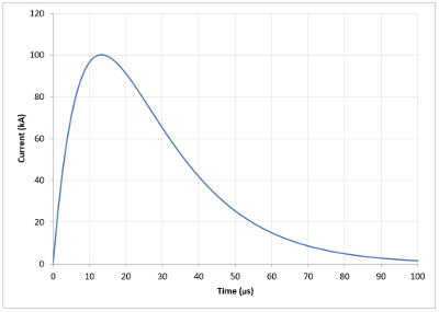
Figure 1: Generated lightning arc profile. The recorded trace of a typical 100 kA peak critically damped oscillatory, 100 µs duration, 18/40 µs generated lightning waveform. Please click here to view a larger version of this figure.
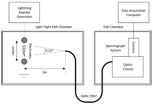
Figure 2: Experimental setup. A schematic of the experimental setup (not to scale), where light from a generated lightning arc between two electrodes is transported via a fiber optic to the spectroscopic system, consisting of an optics chassis and digital camera. Please click here to view a larger version of this figure.

Figure 3: Spectrograph setup. A schematic of the spectrograph system (not to scale), where light from the fiber optic is turned into a spectrum, via a grating, which is then recorded by a digital camera. Please click here to view a larger version of this figure.
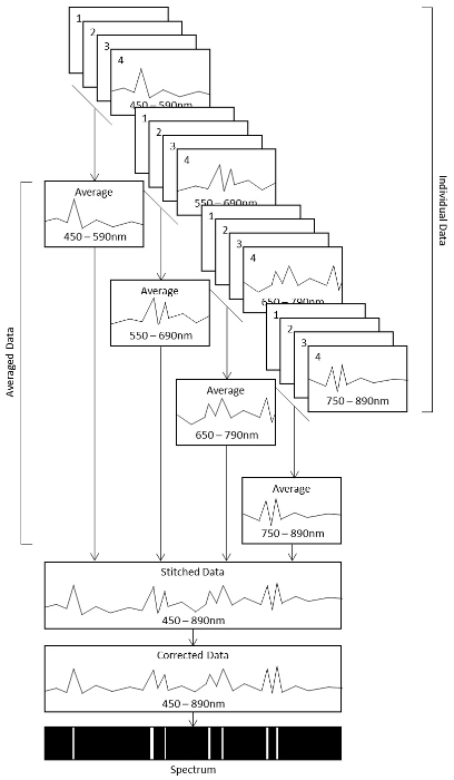
Figure 4: Collating, processing, and presenting spectral data. An illustration of the steps used to collate, average, stitch, and correct data towards achieving a broad high resolution spectrum. Please click here to view a larger version of this figure.
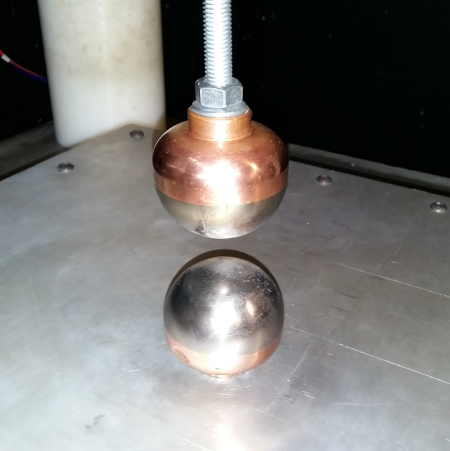
Figure 5: Electrode configuration. An image of the two 6 mm diameter hemispherical tungsten electrodes fixed to copper mountings positioned 14 mm apart within the lightning rig. Please click here to view a larger version of this figure.
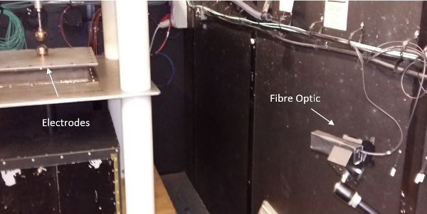
Figure 6: Fiber optic configuration. An image of the fiber optic positioned at the same height and at a distance of 2 m from the mounted electrodes. Please click here to view a larger version of this figure.

Figure 7: Wavelength calibration. (a) A table of three known Mercury lines against the pixel number at which they were measured, and (b) a plot of each point (crosses) and a straight-line fit (dashed line) giving an equation (inset) allowing pixels to be converted to wavelength. This is done for multiple known atomic lines across the entire wavelength range. Please click here to view a larger version of this figure.
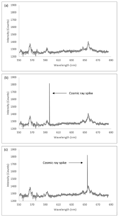
Figure 8: Cosmic ray interference. Spectral data from a 100 kA laboratory generated lightning arc in the 550 nm to 690 nm range showing: (a) data with no cosmic ray interference, and (b) and (c) data with characteristic cosmic ray spikes. Please click here to view a larger version of this figure.
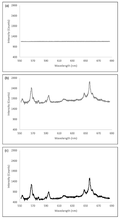
Figure 9: Subtraction of background. Spectral data from a 100 kA laboratory generated lightning arc in the 550 nm to 690 nm range showing: (a) averaged background data, (b) raw data, and (c) data with average background subtracted. Please click here to view a larger version of this figure.
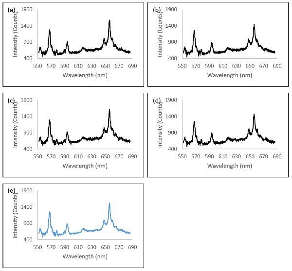
Figure 10: Averaging data. Spectral data from a 100 kA laboratory generated lightning arc in the 550 nm to 690 nm range showing: (a-d) individual data, and (e) averaged data. Please click here to view a larger version of this figure.
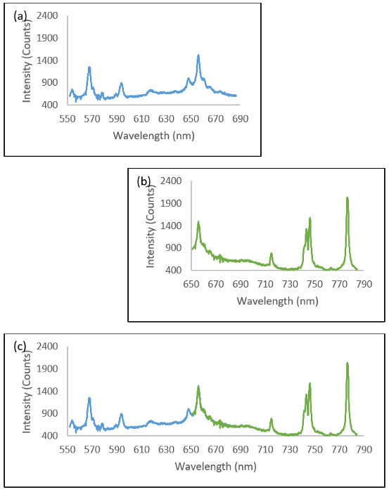
Figure 11: Stitching data. Spectral data from a 100 kA laboratory generated lightning arc showing: (a) the 550 nm to 690 nm range, (b) the 650 to 790 nm range, and (c) the two overlaid datasets with a 650 nm to 690 nm overlap. The overlap region is then averaged. Please click here to view a larger version of this figure.
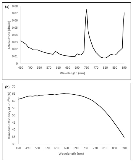
Figure 12: Correcting data. Plots in the 450 nm to 890 nm wavelength range for (a) fiber attenuation, and (b) spectrograph camera quantum efficiency provided by respective manufacturers. These are used to correct the stitched spectral data accordingly. Please click here to view a larger version of this figure.
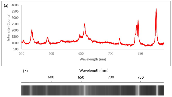
Figure 13: Presenting data. Examples of (a) a graphical data plot and (b) an intensity plot representing the spectrum of a 100 kA laboratory generated lightning arc in the 550 nm to 790 nm wavelength range. Please click here to view a larger version of this figure.
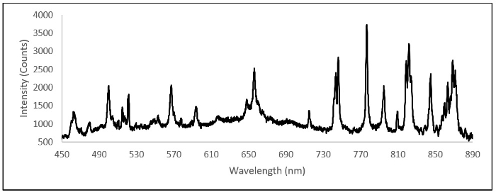
Figure 14: Typical graphical data. A typical averaged, stitched, and corrected graphical plot in the 450 nm to 890 nm wavelength range for a 100 kA laboratory generated lightning arc. Please click here to view a larger version of this figure.

Figure 15: Typical intensity plot. A typical averaged, stitched, and corrected intensity plot in the 450 nm to 890 nm wavelength range for a 100 kA laboratory generated lightning arc. Please click here to view a larger version of this figure.

Figure 16: Chemical element identification. An illustration of spectral line chemical element identification for first order ionization levels using a publicly available database24. Elements in the air (nitrogen, oxygen, argon, helium) and in the electrode (tungsten) have been identified. This spectrum is near-identical to that in reference14 as it uses the same apparatus to analyze the same type of lightning arc. This figure has been adapted from reference14. Please click here to view a larger version of this figure.
Discussion
Spectroscopy is a useful tool for identifying chemical element reactions during both natural and generated lightning strikes. Given a sufficiently accurate and reproducible experimental setup, further analysis on the data can reveal a variety of other lightning properties. It has, for example, been used to verify that the spectra of laboratory generated lightning arcs are spectrally similar to natural lightning and that the addition of other materials into the lightning arc can alter this spectrum significantly14. The method can also be used for other light emitting events such as fast electrical discharges, partial discharges, sparking, and other related phenomena in high voltage systems, where the simultaneous identification of multiple atomic lines or elements across a broad spectrum is important.
The most critical step is to ensure the correct parameters are used when setting up the spectrograph, such as the slit, grating, and camera settings, to acquire the best data possible resulting in strong, sharp spectral peaks. Efforts should be made to also ensure that the detector is not saturated when optimizing the signal. The position of the fiber can also be adjusted and/or collimated to improve light intensity, as well as ensuring that any stray light not part of the lightning event is either eliminated or removed as part of the background imaging process. This may take some trial and error. The ability of the lightning generator used to reproduce the same lightning event accurately with minimal variation, or to understand where any variations may come from so that they can be controlled, is important in obtaining reliable and repeatable spectroscopic results.
Alterations can be made to this setup to assess different parts of the electromagnetic spectrum further into the UV and IR bands where imaging technology allows and depending on the type of event being imaged. For example, extending the wavelength range below 450 nm can reveal further atomic and molecular lines, such as emissions from NO and OH radicals. Adjusting the spectrograph grating to give a lower resolution over a broader range may help to identify interesting features, which can then be analyzed using a higher resolution narrower range grating.
The main advantage of this technique is that it is entirely non-intrusive, so it does not require any alteration to the lightning generator. By transporting the light via a fiber optic, the amount of electrical interference from the harsh electromagnetic environment is reduced, which other systems, such as cameras, may experience if not sufficiently shielded. This means that the data from a spectrograph potentially have much lower noise and less interference than other instruments. This specific technique is limited by its lack of time resolution and subsequent lack of further characterization of the lightning arc. For example, high-speed spectrographs do exist which can produce time resolved spectral data leading to temperature and electron density measurements.
It is expected that spectroscopy will become an important tool, alongside other diagnostic instrumentation, in understanding laboratory generated lightning arcs. It will contribute complimentary information on characteristic lightning event signatures and be used to identify the reactive chemical elements within the arc. Further development of this technique may also result in the derivation of additional characteristics.
Disclosures
The authors have nothing to disclose.
Acknowledgements
The authors gratefully acknowledge the financial support provided by the Sêr Cymru National Research Network in Advanced Engineering and Materials (NRN073) and Innovate UK via the Aerospace Technology Institute (113037).
Materials
| Name | Company | Catalog Number | Comments |
| Lightning Generator, including EMI shielded chambers, lightning rig and associated control and safety systems | Cardiff University | N/A | Designed, developed and constructed by Cardiff University |
| 60mm diameter tungsten electrodes with copper mountings | Unknown | N/A | Available from any specialist electrode / high voltage equipment manufacturer |
| Spectrograph, including chassis, camera, optic fibre and control software | Andor | Chassis: SR-303i-B-SIL | |
| Camera: DU420A-BU2 | |||
| Optic Fibre: 249309 SR-OPT-8018-9RX | |||
| Software: Solis v4.25 | |||
| Mercury argon calibration source | Ocean Optics | HG-1 | |
| Anaylsis software | Microsoft | Excel 2016 |
References
- Wallace, L. The Spectrum of Lightning. Astrophys. J. 139, 994(1963).
- Orville, R. E. A high-speed time-resolved spectroscopic study of the lighting return stroke. J. Atmos. Sci. 25, 827-856 (1968).
- Orville, R. E., Salanave, L. E. Lightning spectroscopy-photographic techniques. Appl. Opt. 9 (9), 1775-1791 (1970).
- Salanave, L. E. Lightning spectroscopy-photographic techniques 2. Appl. Opt. 10 (1), 206-207 (1971).
- Krinder, E. P. Lightning spectroscopy. Nucl. Instrum. Methods. 110, 411-419 (1973).
- Orville, R. E. Daylight spectra of individual lightning flashes in the 370-690 nm region. J. App. Meteorol. 19 (4), 470(1980).
- Orville, R., Henderson, R. Absolute spectral irradiance measurements of lightning from 375 to 880 nm. J. Atmos. Sci. 41 (21), 3180-3187 (1984).
- Warner, T. A., Orville, R. E., Marsh, J. L., Huggins, K. Spectral (600-1050 nm) time exposures (99.6 µs) of a lightning stepped leader. J. Geophys. Res. 116, 12210(2011).
- Zhao, J., Yuan, P., Cen, J., Liu, J., Wang, J., Zhang, G. Characteristics and applications of near-infrared emissions from lightning. J. of Appl. Phys. 114, 163303(2013).
- Walker, T. D., Christian, H. J. Novel observations in lightning spectroscopy. XV International Conference on Atmospheric Electricity. , USA. (2014).
- Cen, J., Yuan, P. Spectral characteristics of lightning dart leader propagating in long path. Atmos. Res. 164-165, 95-98 (2015).
- Xue, S., Yuan, P., Cen, J., Wang, X. Spectral observations of a natural bipolar cloud-to-ground lightning. J. Geophys. Res.: Atmos. 120, 1972-1979 (2015).
- Sousa Martins, R., Zaepffel, C., Chemartin, L., Lalande, P. h, Soutiani, A. Characterization of a high current pulsed arc using optical emission spectroscopy. J. of Phys. D: Appl. Phys. 49, 415205(2016).
- Mitchard, D., Clark, D., Carr, D., Haddad, A. Techniques for the comparison of light spectra from natural and laboratory generated lightning current arcs. Appl. Phys. Lett. 109, 093502(2016).
- Uman, M. A. Determination of lightning temperature. J. Geophys. Res. 74 (4), 949-957 (1969).
- Prueitt, L. M. The excitation temperature of lightning. J. Geophys. Res. 68, 803-811 (1963).
- Uman, M. A. Quantitative lightning spectroscopy. IEEE Spectrum. 3, 102-110 (1966).
- Hill, R. D. A survey of lightning energy estimates. Rev. Geophys. 17 (1), 155-164 (1979).
- Stone, C., Simpson, H., Leichauer,, Griffiths, H., Haddad, A., Cole, M., Evans, S. Establishment of a lightning test laboratory for direct-effects research. International Conference on Lightning and Static Electricity. , USA. (2013).
- EUROCAE WG-31 and SAE Committee AE4L. , ED-84 (1997).
- Mitchard, D., Clark, D., Stone, C., Haddad, A. Preliminary results for spectroscopic lightning arc measurements. International Conference on Lightning and Static Electricity. , France. (2015).
- Mitchard, D., Jamoshid, N. S., Stone, C., Haddad, A. Investigation of lightning direct effects on aircraft materials. International Conference on Lightning Protection. , Portugal. (2016).
- Mitchard, D., Jamoshid, N. S., Clark, D., Carr, D., Haddad, A. Investigation of lightning direct effects on aircraft materials. Electrical Systems for Aircraft, Railway and Ship Propulsion and Road Vehicles & International Transportation Electrification Conference. , France. (2016).
- Kamira, J., Ralchenko, J. Reader and NIST ASD Team, NIST Database. , version 5.2 (2014).
Reprints and Permissions
Request permission to reuse the text or figures of this JoVE article
Request PermissionThis article has been published
Video Coming Soon
Copyright © 2025 MyJoVE Corporation. All rights reserved