
A subscription to JoVE is required to view this content. Sign in or start your free trial.
Method Article
An Optimized Rhizobox Protocol to Visualize Root Growth and Responsiveness to Localized Nutrients
In This Article
Summary
Visualizing and measuring root growth in situ is extremely challenging. We present a customizable rhizobox method to track root development and proliferation over time in response to nutrient enrichment. This method is used to analyze maize genotypic differences in root plasticity in response to an organic nitrogen source.
Abstract
Roots are notoriously difficult to study. Soil is both a visual and mechanical barrier, making it difficult to track roots in situ without destructive harvest or expensive equipment. We present a customizable and affordable rhizobox method that allows the non-destructive visualization of root growth over time and is particularly well-suited to studying root plasticity in response to localized resource patches. The method was validated by assessing maize genotypic variation in plasticity responses to patches containing 15N-labeled legume residue. Methods are described to obtain representative developmental measurements over time, measure root length density in resource-containing and control patches, calculate root growth rates, and determine 15N recovery by plant roots and shoots. Advantages, caveats, and potential future applications of the method are also discussed. Although care must be taken to ensure that experimental conditions do not bias root growth data, the rhizobox protocol presented here yields reliable results if carried out with sufficient attention to detail.
Introduction
Although often overlooked compared to their aboveground counterparts, roots play a critical role in plant nutrient acquisition. Given the substantial carbon cost of root construction and maintenance, plants have evolved mechanisms to develop roots only where foraging is worth the investment. Root systems can thus efficiently and dynamically mine resource patches by proliferating in hotspots, upregulating rates of uptake, and rapidly translocating nutrients to the phloem for further transport1. Plasticity responses can vary widely among plant species or genotypes2,3 and depending on the chemical form of the nutrient involved4,5. Variation in root plasticity should be explored further, as understanding complex root responses to heterogeneous soil resources could inform breeding and management strategies to increase nutrient use efficiency in agriculture.
Despite its necessity and relevance for understanding plant systems, visualizing and quantifying root plasticity at relevant scales poses technical challenges. Excavating the root crown from the soil ("shovelomics"6) is a common method, but fine roots exploit small pores between soil aggregates, and excavation inevitably leads to some degree of loss of these fragile roots. Furthermore, destructive harvest makes it impossible to follow changes in one root system over time. In situ imaging methods such as X-ray computed tomography allow direct visualization of roots and soil resources at high spatial resolution7, but are expensive and require specialized equipment. Hydroponic experiments avoid constraints associated with extracting roots from soil, but root morphology and architecture differ in aqueous media as compared to the mechanical constraints and biophysical complexity of soils8,9. Finally, rhizosphere processes and functions cannot be integrated with developmental plasticity in these artificial media.
We present a protocol for the construction and use of rhizoboxes (narrow, clear-sided rectangular containers) as a low-cost, customizable method to characterize root growth in soil over time. Specially designed frames encourage roots to grow preferentially against the back panel due to gravitropism, increasing the accuracy of root length measurements. Rhizoboxes are commonly used to study root growth and rhizosphere interactions10,11,12, but the method presented here offers an advantage in simplicity with its single-compartment design and inexpensive materials, and is designed to study root responses to localized nutrients. However, the method could also be adapted to study a range of other root and rhizosphere processes such as intra/interspecies competition, spatial distribution of chemical compounds, microbes, or enzyme activity. Here, we investigate genotypic differences among maize hybrids in response to patches of 15N-labeled legume residue and highlight representative results to validate the rhizobox method.
Protocol
1. Preparation of the Front and Back Panels, and Spacers
- Prepare the front and back panels.
- Cut two pieces of clear 0.635 cm thick acrylic to 40.5 cm wide by 61 cm long per box or purchase pre-cut pieces (see Table of Materials).
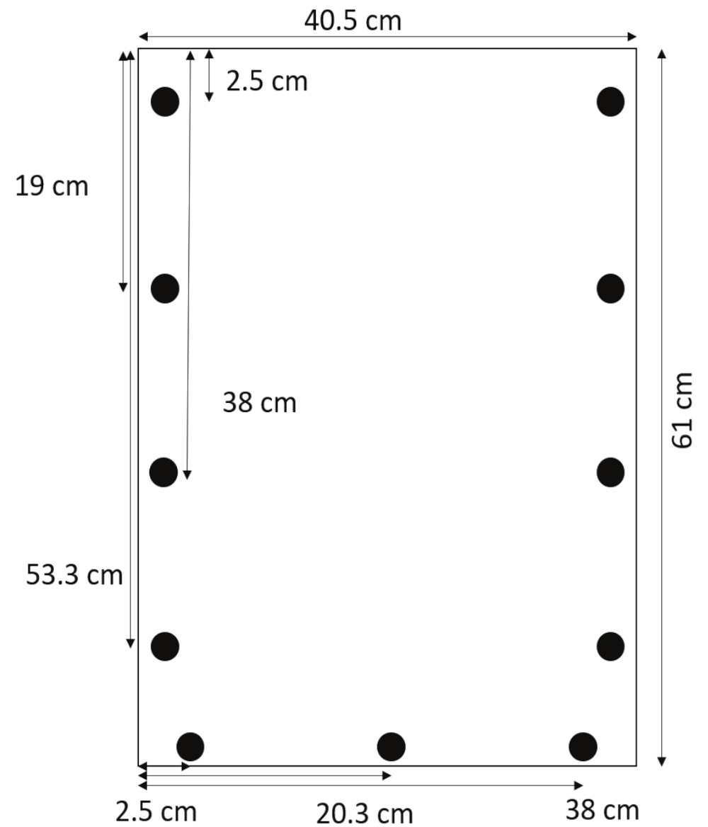
- Using a drill bit designed for acrylic, drill holes 0.635 cm in diameter 1.3 cm from the side edges at 2.5, 19, 38, and 53.3 cm from the top. Drill holes 1.3 cm from the bottom edge at 2.5, 20.3, and 38 cm from the left side (Figure 1).
NOTE: It is most efficient to use a drill press for a stack of six to ten sheets at a time, but a hand drill can also be used. - Remove any protective coverings from the acrylic and gently clean both panels before assembling the boxes.

Figure 1: Layout of drilled holes. Holes are drilled 1.3 cm from the side edges at 2.5, 19, 38, and 53.3 cm from the top, and 1.3 cm from the bottom edge at 2.5, 20.3, and 38 cm from the left margin. Please click here to view a larger version of this figure.
- Prepare the side and bottom spacers.
- Cut three spacers per box from high-density polyethylene (HDPE) or purchase two pre-cut side spacers (0.635 cm thick, 2.5 cm wide, 57 cm long), and one pre-cut bottom spacer (0.635 cm thick, 2.5 cm wide, 40.5 cm long). See the Table of Materials.
- Align the spacers between the front and back panels along the sides and bottom of the box. Using a hand drill or drill press, drill through the existing holes in the front and back again so that the holes pass through all three layers cleanly.
- Hold the layers place using clamps or by installing a combination of bolts, nuts, and washers in each newly drilled hole (see step 3.1).
2. Installation of a Strip of Polyester Batting at the Bottom of the Box
NOTE: This will prevent soil and water from leaking through joints between spacers.
- Cut polyester batting into 2.5 cm wide by 40.5 cm long strips (see the Table of Materials).
- With the back panel lying flat and the spacers on top of it, lay the batting directly above the bottom spacer and hold it in place with the top panel (Figure 2).

Figure 2: Assembled rhizobox with batting. A narrow strip of batting at the bottom of the rhizobox prevents soil and sand from leaking out. Please click here to view a larger version of this figure.
3. Assembly of the Rhizoboxes
- Assemble the rhizoboxes using 20-thread screws (3.2 cm length by 0.635 cm diameter), washers (0.635 cm internal diameter), and hex nuts (sized to fit the screws, see Table of Materials.
- Tighten each screw through a washer, front panel, spacer, back panel, washer, and hex nut. Make sure the screws are very tight; if the box is assembled loosely, soil will spill out through gaps between the panels and side spacers.
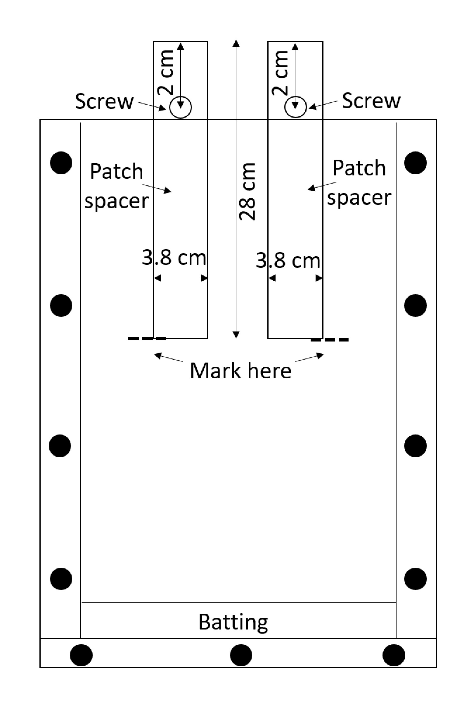
NOTE: Acrylic is easily scratched, and the scratches can interfere with root measurements, so handle the assembled boxes with care. Avoid stacking boxes unless protective material is placed between them. - Prepare two patch spacers (spacers that will be used to create the treatment and control patches) per box. Cut spacers from high-density polyethylene (HDPE) sheets or purchase them pre-cut (0.635 cm thick, 3.8 cm wide, 28 cm long; see Table of Materials). Drill one hole 0.635 cm in diameter in each spacer, 2 cm from the top along the mid-line (Figure 3).

Figure 3: Patch spacers. Screws inserted through the center of HDPE strips keep them from falling into the box. The rhizobox is filled with soil around the spacers, the soil is wetted, and the spacers are removed in order to leave empty treatment and control patches. Please click here to view a larger version of this figure.
- Secure a screw through each hole with a nut so that the spacer can be partially inserted into the rhizobox until the screw prevents it from going further (Figure 3).
NOTE: When the soil is wetted around the spacers and the spacers are removed, two empty spaces will remain that can be filled with the appropriate substrates for the nitrogen-containing treatment patch and control patch.
4. Building PVC Frames to Support the Rhizoboxes at an Angle
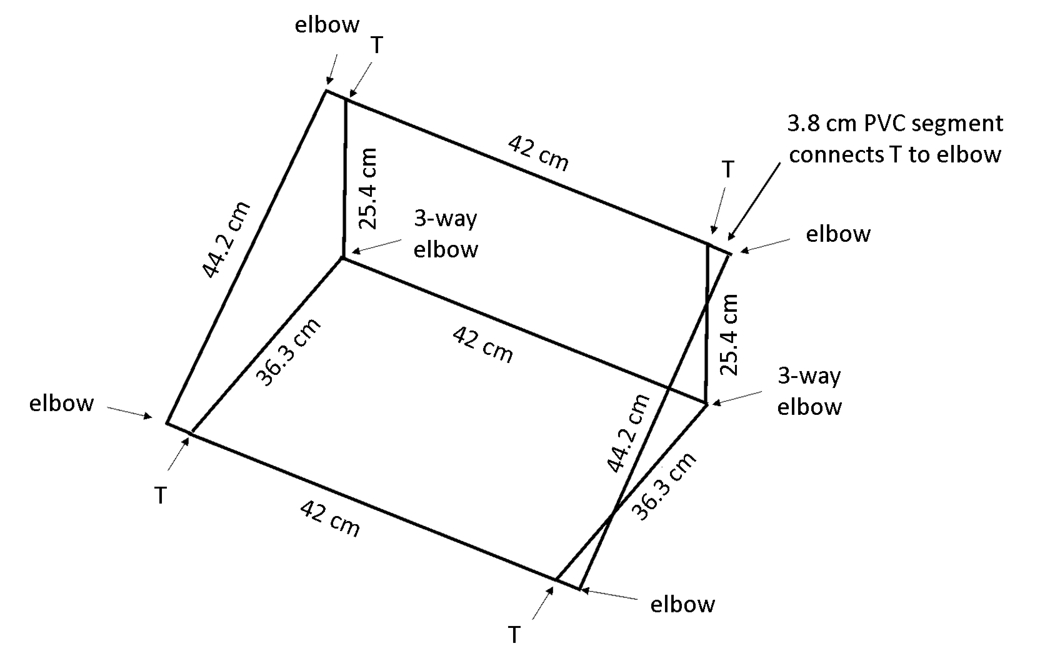
NOTE: When the box is placed at an angle, gravitropism will encourage the roots to grow against the back panel so that all roots are visible for tracing. The polyvinyl chloride (PVC) dimensions in Figure 4 result in a frame that maintains the rhizobox at an approximately 55° angle to the bench.
- Cut 13 pieces of 1.3 cm diameter PVC per box: 2× 44 cm lengths, 3× 42 cm lengths, 2× 36.3 cm lengths, 2× 25.4 cm lengths, and 4× 3.8 cm lengths (see Table of Materials).
NOTE: A chop saw is highly recommended for efficiency and even cuts. - Use 4× 2-way elbows, 2× 3-way elbows, and 4 T-joints (see Table of Materials) to assemble the box as shown in Figure 4.
NOTE: Frames should be stable without additional glue, but PVC glue can be used if necessary.

Figure 4: Frame to support rhizoboxes. The lightweight frame is constructed from PVC cut to the specified lengths and connected using the joint types indicated. Please click here to view a larger version of this figure.
5. Sewing Protective Cases to Reflect Light and Heat
NOTE: Roots avoid light, so these cases exclude light in order to make sure that observed root plasticity responses are driven by the nutrient source in the patches and not by light avoidance. Light deprivation fabric also reduces the temperature inside the rhizoboxes, helping to avoid heat stress.
- Cut the light deprivation fabric (specialized material that is white on one side and black on the other) into pieces approximately 95 cm wide and 69 cm long (see Table of Materials). One piece per box is required.
- Fold each piece in half along the long edge to form a 47.5 cm × 69 cm sleeve. Using a sewing machine needle designed for denim, heavy-duty quilting thread, and a narrow seam, sew along the bottom and ¾ of the way up the side of each sleeve. Pin the top corners together with a safety pin.
6. Preparation of 1:1 (V/V) Soil : Sand Substrate to Fill the Rhizoboxes
- Collect approximately 1,000 cm3 of field soil (from the site of interest) per box. Dry the soil to constant weight in shallow trays at 60 °C.
NOTE: Soil for this experiment was collected immediately following harvest in an organically managed corn field from 0‒10 cm depth. - Grind the soil with a mortar and pestle to pass through a 2 mm sieve. Measure the bulk density of the soil by weighing a known volume of soil.
- Obtain sand (such as play sand, which can be purchased inexpensively from a hardware store; see Table of Materials) and measure the bulk density.
- Measure out equal volumes sand and soil into a bucket and mix thoroughly. Use a funnel to fill the box slowly and evenly to 2.5 cm from the top, without shaking the box to cause the substrate to settle. Measure this volume of substrate; it should be approximately 1,272 cm3.
- Multiply the bulk density of sand by half this volume to obtain the mass of sand needed for each box. Do the same with the bulk density of soil to obtain the mass of soil needed for each box.
NOTE: For the field soil and sand used in this experiment, this was 976 g of sand and 774 g of soil, but these amounts will vary depending on the bulk density of the soil used. - Label one large zip-top plastic bag per rhizobox, weigh the appropriate masses of sand and soil into the bag, and homogenize thoroughly.
- Analyze this 1:1 soil-and substrate for nutrient content and the natural abundance of 15N (δ15N).
7. Substrate Preparation for the Treatment and Control Patches
- Label two small zip-top plastic bags per rhizobox, one for the treatment patch and one for the control patch. Weigh 30 g of the soil : sand substrate from each large bag (step 6.6) into the two corresponding small bags.
- Mix the substrate with a 15N-labeled nitrogen source for the treatment patch. For this, weigh out 1 g of 15N-labeled plant residue or other N-source (the amount can be adjusted as desired) into each treatment bag (small zip-top bag), and mix thoroughly.
NOTE: For this experiment, a mixture of 15N-labeled clover and vetch residue was used. Clover and vetch seeds were planted in a 1:1 mix of vermiculite and sand, and grown under greenhouse conditions. Plants were watered daily with deionized water and twice weekly with 1/100 strength of Long-Ashton solution13 containing 15N-labeled nitrogen sources. All aboveground biomass was harvested at four weeks after planting, dried, and ground to pass through a 2 mm sieve. If a different nutrient is chosen, particularly if that element is mobile in soil, pilot experiments to test for leaching are encouraged. Slow-release forms of nutrients could be used or a different rhizobox design could be chosen to restrict leaching (e.g., by separate compartments10) if necessary.
8. Loading Rhizobox with Substrate, and Establishing Treatment and Control Patches
- Weigh each empty rhizobox and record the weights for later use.
- Insert two patch spacers (see step 3.2) into one rhizobox until the screw prevents them from going further. Mark the depth of the bottom edge with a light mark on the side of the rhizobox (Figure 3) and remove the spacers.
- Using a funnel with a stem opening that is as narrow as the rhizobox opening, fill the rhizobox from the corresponding large bag of substrate to the marked depth. Move the funnel back and forth slowly and evenly so that the substrate fills uniformly and does not create preferential flow channels.
- When the substrate level reaches the marked depth, put the spacers back in 5 cm from each side of the box. Continue filling the box until the substrate level is approximately 5 cm from the top of the box (there should be substrate remaining in the bag).
- Wet thoroughly around each spacer.
NOTE: In this experiment, this was achieved by delivering 50 mL of water through drip emitters inserted between the outer edge of each spacer and the side of the rhizobox, and pouring 50 mL of water evenly between the two spacers. Slow irrigation is necessary for uniform wetting. - Remove the spacers while the soil is wet, leaving an empty cavity for the patches.
- Tape a transparency film to the outside of each rhizobox (see Table of Materials). Mark one side as treatment and one as control, and fill the patches from the appropriate bags using the funnel. Trace the boundaries of each patch on the transparency using permanent marker.
- Fill the rhizobox evenly with the remaining substrate. Trace the top of the substrate on the transparency.
- Repeat for the remaining rhizoboxes. Save all the bags for harvest.
9. Even Watering to 60% Water-Holding Capacity
NOTE: This amount of soil moisture was found to prevent plants from experiencing drought stress while preventing the development of anoxic conditions or algal growth.
- Measure the water-holding capacity (WHC) of the substrate14.
- Calculate the ideal weight of each box; here defined as the sum of the weight of the empty rhizobox combined with the weight of the substrate at 60% water-holding capacity.
- Multiply the WHC (grams of water / grams of dry substrate) by 0.6 to obtain the mass of water held in the substrate at 60% WHC. Add this mass to the mass of dry substrate and the mass of the 15N source.
- Add the empty weight of each box to the number obtained above.
- Weigh the boxes once they have been filled. Subtract the weight of each box (in g) at this point from its ideal weight (in g) calculated in step 9.2. Water with this volume (in mL) of de-ionized (DI) water slowly and evenly.
NOTE: This step may be done using drip irrigation or watering by hand. If watering by hand, allow the water to percolate completely before adding more to avoid heterogenous soil moisture conditions and preferential flow channels.
10. Seed Germination and Transplantation
- If using unplanted controls, set those rhizoboxes aside.
- Surface-sterilize maize seeds by stirring for 1 min in 5% NaOCl, then rinse thoroughly in DI water.
NOTE: In this experiment, seeds of six different maize genotypes were used in order to investigate genotypic differences in root plasticity. - Germinate sterilized seeds by placing them on a wet laboratory tissue (e.g., Kimwipe) inside Petri dishes and covering with another moist tissue. There should not be any standing water. Place Petri dishes in a dark place for 48‒72 h until the radicle just begins to emerge.
- Use a narrow spatula to dig a hole to 2.5 cm depth at the center of each rhizobox. Transplant a germinated seed into the hole, ensuring that the radicle is oriented directly downwards.
NOTE: If the radicle is angled towards either patch, the comparison of root growth rates will be biased. - Trace the location of the seed on the transparency.
- Cover the seed and water in with up to 50 mL of DI water.
11. Plants Growth
- Grow plants for 25 days (or as long as desired), maintaining 60% WHC throughout the growing period. Monitor root growth by tracing the roots.
- Weigh each box every 3‒4 days and water until it is within 5 g of its ideal weight. Stop watering the rhizoboxes four days before harvest to facilitate separation of the panels. Remove weeds by hand frequently so that only plant roots of interest are present.
- Trace visible roots every 3‒4 days using a permanent marker with clearly distinguishable colors for each tracing day.
NOTE: Different diameter markers can be used for primary and lateral roots, if desired. It can be useful to define criteria for root tracing at the outset since a degree of subjectivity is involved, particularly if multiple researchers will be tracing roots or if roots of different orders or diameter are to be distinguished with different markers. In this experiment, the accuracy of tracing visible roots on only one side of the box was tested by tracing visible roots on both sides and comparing total root length measured on the scanned transparencies to total root length measured by washing and scanning roots. The correlation between traced and scanned root length was significant regardless of whether only the back transparency or both transparencies were used. It is therefore possible to just trace visible roots on the back panel.
12. Harvesting Shoots, and Obtaining Root and Soil Samples for Analysis
- Lay the first rhizobox flat and remove all the screws.
- Harvest the shoot samples. Clip shoots at the base, rinse off any soil with DI water, and dry at 60 °C. Grind shoots with a mortar and pestle to pass through a 2 mm sieve and weigh subsamples into tin capsules for isotope analysis (see section 14).
- Using the transparency as a guide, cut around the treatment and control patches with a razor. Use a spoon or spatula to scoop the roots and the adhering rhizosphere soil into the respective treatment or control bag.
NOTE: While many methods exist to separate rhizosphere soil, the soil under the influence of plant roots15, and the rhizosphere can be considered a gradient rather than a strictly delineated zone16, this method follows the widely used definition of soil that adheres to plant roots after shaking17. - Scoop the remaining roots and soil into the third bag.
- Pass the treatment, control, and bulk samples through a 2 mm sieve to separate roots from substrate, removing any visible roots or fragments >1 cm in length with fine tweezers. Keep these samples separate from one another for a total of three root and three substrate samples.
13. Validation of Tracings and Estimation of Relative Root Growth Rates
- Scan treatment, control, and bulk samples and calculate the root length.
- Working with one sample at a time, rinse roots carefully with DI water to remove any remaining substrate. Arrange samples in a clear tray so that the roots are not overlapping.
- Scan samples using a scanner compatible with root analysis software (e.g., WinRhizo). Ensure that the software is calibrated to reliably distinguish roots from the image background.
- Use the software to measure total root length and root length in the diameter classes of interest (e.g., <0.2 mm, 0.2‒0.4 mm, 0.4‒0.8 mm, 0.8‒1.6 mm, >1.6 mm).
- Calculate root length density (RLD) for treatment and control patches and for each rhizobox as a whole.
- Calculate the volume of treatment and control patches by multiplying the area traced on each transparency (see step 8.1) by 0.635 cm, the depth of the box. Use those volumes to calculate root length density in treatment and control patches using the total root length in each patch (see step 13.1.3).

- Calculate the volume of substrate in each rhizobox by multiplying the area traced on the transparency (see step 8.1) by 0.635 cm. Calculate RLD as for the treatment and control patches.

- Calculate the volume of treatment and control patches by multiplying the area traced on each transparency (see step 8.1) by 0.635 cm, the depth of the box. Use those volumes to calculate root length density in treatment and control patches using the total root length in each patch (see step 13.1.3).
- Validate the root tracing method by comparing scanned root systems and traced images.
- Scan each transparency and calculate total root length using the software. Save the scanned image for growth rate calculations.
- Sum the total root length measurements of treatment, control, and bulk samples for each box (see step 13.1.3).
- Test the scanned and traced measurements of total root length to see whether the correlation is statistically significant.
NOTE: If so, the tracing method is validated, and relative growth rates can be calculated at each time point. If not, only the scanned root system data provides an accurate indication of root growth. This could be the case if tracing methodology was inconsistent or if roots were not equally visible for all genotypes, for example.
- If the tracing method was validated, calculate relative root growth rates for each rhizobox.
- Use root analysis software calibrated to distinguish between the chosen tracing colors to measure total root length in treatment, control, and bulk samples at each time point. Calculate cumulative total root length at each time point.
- Calculate relative root growth rates (RGRroot) for each rhizobox as well as for treatment and control patches for each time interval t1-t2 as follows.

NOTE: Here L1 is total root length in the patch (cumulative sum from 11.3) at t1 days after transplanting (DAT) and L2 is total root length in the patch at t2 DAT.
14. Analysis of 15N partitioning among root, shoot, and treatment soil samples
- Dry roots at 60 °C, weigh biomass, and grind to pass through a 2 mm sieve.
- Dry subsamples of treatment soil at 60 °C.
- Package roots and treatment into tin capsules as with the shoots.
NOTE: Ideal sample weight per capsule should be calculated separately for shoots, roots, and soil based on the estimated C/N ratio of the material to achieve the target amount of total N for analysis. Contact the stable isotope facility where the samples are to be submitted for more information. For this experiment, the sample preparation instructions and Sample Weight Calculator provided by the UC Davis Stable Isotope Facility were followed18.
CAUTION: Take special care to mix samples evenly before packaging into capsules and prepare multiple capsules per sample. If samples are not evenly mixed, apparent recovery of 15N can exceed the amount originally present. - Analyze total N, δ15, and 15N content of each shoot, root, and treatment soil sample.
NOTE: In this experiment, plant samples were analyzed via combustion with a PDZ Europa ANCA-GSL elemental analyzer interfaced to a PDZ Europa 20-20 isotope ratio mass spectrometer at the UC Davis Stable Isotope Facility (UCD SIF). Soil samples were analyzed with an Elementar Vario EL Cube elemental analyzer interfaced to a PDZ Europa 20-20 isotope ratio mass spectrometer at the UCD SIF. - Calculate the amount of 15N obtained from the label in plant shoot and root samples.
- First, calculate the amount of 15N in excess of atmospheric 15N in each pool, 15P*:

where 15P is the 15N content in atomic% of the pool of interest. - Second, calculate the amount of 15N in excess of atmospheric 15N in the label, 15L*:

where 15L is the 15N content in atomic% of the labeled N source. - Third, calculate the amount of total N in each pool, Np:

where mp is the mass of the pool (e.g., total dry shoot or root biomass) and %p is the percent of N of that pool. - Finally, use the results of 14.5.1‒14.5.3 in the Ndff equation19 to calculate the amount of N obtained from the label, Nl:

NOTE: The Ndff equation is used to determine the amount of N from a labeled source that is recovered by plants. It assumes that no isotopic discrimination occurs during N uptake by the plant and is generally valid for N sources enriched ~1‒10%19.
- First, calculate the amount of 15N in excess of atmospheric 15N in each pool, 15P*:
Results
Roots grew preferentially against the back of the box, as anticipated. Total traced root length on the back of the box ranged from 400 to 1,956 cm, as compared to 93-758 cm on the front of the box. Pairwise Pearson correlation coefficients were calculated between scanned root length and traced root length on the front of the box, back of the box, and the sum of front and back was used to determine whether tracing accurately reflected total root length (n = 23, as the plant in one box died...
Discussion
The rhizoboxes described in this protocol can be used to answer varied questions in root and rhizosphere science, and have found diverse uses elsewhere10,20,21,22,23,24,25. Other researchers have captured time-lapse images of rhizoboxes21,...
Disclosures
The authors have nothing to disclose.
Acknowledgements
The authors would like to acknowledge anonymous reviewers for their feedback, as well as J.C. Cahill and Tan Bao for initial guidance on developing the rhizobox protocol. Funding was provided by the Foundation for Food and Agriculture Research, the US Department of Agriculture (USDA) National Institute of Food and Agriculture, Agricultural Experiment Station Project CA-D-PLS-2332-H, to A.G. and by the UC Davis Department of Plant Sciences through a fellowship to J.S.
Materials
| Name | Company | Catalog Number | Comments |
| 1.27 cm diameter PVC pipe | JM Eagle | 530048 | 305 cm per box, cut into lengths as specified in the protocol |
| PVC side elbows | Lasco | 315498 | 2 per box |
| PVC 90-degree elbows | Charlotte | PVC 02300 0600 | 4 per box |
| PVC T joints | Charlotte | PVC 02402 0600 | 4 per box |
| Extruded acrylic panes | TAP Plastics | N/A | 2 per box, 0.64 cm thick x 40.5 cm wide x 61 cm long |
| HDPE spacers (sides) | TAP Plastics | N/A | 2 per box, 0.64 cm thick x 2.5 cm wide x 57 cm long |
| HDPE spacers (bottom) | TAP Plastics | N/A | 1 per box, 0.64 cm thick x 2.5 cm wide x 40.5 cm long |
| HDPE spacers (patch) | TAP Plastics | N/A | 2 per box, 0.64 cm thick x 3.8 cm wide x 28 cm long |
| Polyester batting | Fairfield | #A-X90 | 2.5 cm x 40.5 cm strip per box |
| 20-thread screws | N/A | N/A | 3.2 cm long, 0.64 cm diameter |
| Washers | N/A | N/A | 0.64 cm internal diameter |
| Hex nuts | N/A | N/A | sized to fit the screws |
| Light deprivation fabric | Americover, Inc. | Bold 8WB26.5 | 1 piece 95 cm wide and 69 cm long per box |
| Sand | Quikrete | No. 1113 | |
| Field soil | N/A | N/A | |
| Transparencies for tracing | FXN | FXNT1319100S | One per side of the box to be traced |
References
- Hodge, A. Roots: The Acquisition of Water and Nutrients from the Heterogeneous Soil Environment. Progress in Botany 71. , 307-337 (2010).
- Grossman, J. D., Rice, K. J. Evolution of root plasticity responses to variation in soil nutrient distribution and concentration. Evolutionary Applications. 5 (8), 850-857 (2012).
- Zhang, H., Forde, B. G. An Arabidopsis MADS box gene that controls nutrient-induced changes in root architecture. Science. 279 (5349), 407-409 (1998).
- Hodge, A., Stewart, J., Robinson, D., Griffiths, B. S., Fitter, A. H. Competition between roots and soil micro-organisms for nutrients from nitrogen-rich patches of varying complexity. Journal of Ecology. 88 (1), 150-164 (2000).
- Trachsel, S., Kaeppler, S. M., Brown, K. M., Lynch, J. P. Shovelomics: high throughput phenotyping of maize (Zea mays L.) root architecture in the field. Plant and Soil. 341 (1-2), 75-87 (2011).
- Rogers, E. D., Monaenkova, D., Mijar, M., Nori, A., Goldman, D. I., Benfey, P. N. X-ray computed tomography reveals the response of root system architecture to soil texture. Plant Physiology. , (2016).
- Groleau-Renaud, V., Plantureux, S., Guckert, A. Effect of mechanical constraint on nodal and seminal root system of maize plants. Comptes Rendus De L Academie Des Sciences Serie Iii-Sciences De La Vie-Life Sciences. 321 (1), 63-71 (1998).
- Lin, Y., Allen, H. E., Di Toro, D. M. Barley root hair growth and morphology in soil, sand, and water solution media and relationship with nickel toxicity. Environmental Toxicology and Chemistry. 35 (8), 2125-2133 (2016).
- Wenzel, W. W., Wieshammer, G., Fitz, W. J., Puschenreiter, M. Novel rhizobox design to assess rhizosphere characteristics at high spatial resolution. Plant and Soil. 237 (1), 37-45 (2001).
- Spohn, M., Carminati, A., Kuzyakov, Y. Soil zymography - A novel in situ method for mapping distribution of enzyme activity in soil. Soil Biology and Biochemistry. 58, 275-280 (2013).
- Vollsnes, A. V., Futsaether, C. M., Bengough, A. G. Quantifying rhizosphere particle movement around mutant maize roots using time-lapse imaging and particle image velocimetry. European Journal of Soil Science. 61 (6), 926-939 (2010).
- Hewitt, E. J. . Sand and Water Culture Methods Used in the Study of Plant Nutrition. , (1966).
- Choudhary, M. I., Shalaby, A. A., Al-Omran, A. M. Water holding capacity and evaporation of calcareous soils as affected by four synthetic polymers. Communications in Soil Science and Plant Analysis. 26 (13-14), 2205-2215 (1995).
- Bakker, P. A. H. M., Berendsen, R. L., Doornbos, R. F., Wintermans, P. C. A., Pieterse, C. M. J. The rhizosphere revisited: root microbiomics. Frontiers in Plant Science. 4, 2013 (2013).
- McNear, D. H. The Rhizosphere - Roots, Soil, and Everything In Between. Nature Education Knowledge. 4 (3), 1 (2013).
- Ortas, I. Determination of the extent of rhizosphere soil. Communications in Soil Science and Plant Analysis. 28 (19-20), 1767-1776 (1997).
- . Carbon (13C) and Nitrogen (15N) Sample Preparation Available from: https://stableisotopefacility.ucdavis.edu/13cand15nsamplepreparation.html (2018)
- Barraclough, D. 15N isotope dilution techniques to study soil nitrogen transformations and plant uptake. Fertilizer research. 42 (1-3), 185-192 (1995).
- Belter, P. R., Cahill, J. F. Disentangling root system responses to neighbours: identification of novel root behavioural strategies. AoB PLANTS. 7, (2015).
- Nagel, K. A., et al. GROWSCREEN-Rhizo is a novel phenotyping robot enabling simultaneous measurements of root and shoot growth for plants grown in soil-filled rhizotrons. Functional Plant Biology. 39 (11), 891-904 (2012).
- Adu, M. O., Yawson, D. O., Bennett, M. J., Broadley, M. R., Dupuy, L. X., White, P. J. A scanner-based rhizobox system enabling the quantification of root system development and response of Brassica rapa seedlings to external P availability. Plant Root. 11, 16-32 (2017).
- Neumann, G., George, T. S., Plassard, C. Strategies and methods for studying the rhizosphere-the plant science toolbox. Plant and Soil. 321 (1-2), 431-456 (2009).
- Bodner, G., Alsalem, M., Nakhforoosh, A., Arnold, T., Leitner, D. RGB and Spectral Root Imaging for Plant Phenotyping and Physiological Research: Experimental Setup and Imaging Protocols. JoVE (Journal of Visualized Experiments). (126), e56251-e56251 (2017).
- Kuchenbuch, R. O., Ingram, K. T. Image analysis for non-destructive and non-invasive quantification of root growth and soil water content in rhizotrons. Journal of Plant Nutrition and Soil Science. 165 (5), 573-581 (2002).
- Dresbøll, D. B., Thorup-Kristensen, K., McKenzie, B. M., Dupuy, L. X., Bengough, A. G. Timelapse scanning reveals spatial variation in tomato (Solanum lycopersicum L.) root elongation rates during partial waterlogging. Plant and Soil. 369 (1-2), 467-477 (2013).
- Wu, J., et al. RhizoChamber-Monitor: a robotic platform and software enabling characterization of root growth. Plant Methods. 14 (1), 44 (2018).
- Rogers, S. W., Moorman, T. B., Ong, S. K. Fluorescent In Situ Hybridization and Micro-autoradiography Applied to Ecophysiology in Soil. Soil Science Society of America Journal. 71 (2), 620-631 (2007).
- Eickhorst, T., Tippkötter, R. Detection of microorganisms in undisturbed soil by combining fluorescence in situ hybridization (FISH) and micropedological methods. Soil Biology and Biochemistry. 40 (6), 1284-1293 (2008).
- Spohn, M., Kuzyakov, Y. Distribution of microbial- and root-derived phosphatase activities in the rhizosphere depending on P availability and C allocation - Coupling soil zymography with 14C imaging. Soil Biology and Biochemistry. 67, 106-113 (2013).
- Lv, G., Kang, Y., Li, L., Wan, S. Effect of irrigation methods on root development and profile soil water uptake in winter wheat. Irrigation Science. 28 (5), 387-398 (2010).
- Asseng, S., Ritchie, J. T., Smucker, A. J. M., Robertson, M. J. Root growth and water uptake during water deficit and recovering in wheat. Plant and Soil. 201 (2), 265-273 (1998).
- Hernandez-Ramirez, G., et al. Root Responses to Alterations in Macroporosity and Penetrability in a Silt Loam Soil. Soil Science Society of America Journal. 78 (4), 1392-1403 (2014).
- Zhang, Y. L., Wang, Y. S. Soil enzyme activities with greenhouse subsurface irrigation. Pedosphere. 16 (4), 512-518 (2006).
- Robinson, D., Hodge, A., Griffiths, B. S., Fitter, A. H. Plant root proliferation in nitrogen-rich patches confers competitive advantage. Proceedings of the Royal Society of London B: Biological Sciences. 266 (1418), 431-435 (1999).
- Lobet, G., Draye, X. Novel scanning procedure enabling the vectorization of entire rhizotron-grown root systems. Plant Methods. 9, 1 (2013).
- Swarup, R., Wells, D. M., Bennett, M. J. Root Gravitropism. Plant Roots: The Hidden Half. , (2013).
- Smit, A. L., Bengough, A. G., Engels, C., van Noordwijk, M., Pellerin, S., van de Geijn, S. C. . Root Methods: A Handbook. , (2000).
- van Dusschoten, D., et al. Quantitative 3D Analysis of Plant Roots Growing in Soil Using Magnetic Resonance Imaging1[OPEN]. Plant Physiology. 170 (3), 1176-1188 (2016).
- Metzner, R., et al. Direct comparison of MRI and X-ray CT technologies for 3D imaging of root systems in soil: potential and challenges for root trait quantification. Plant Methods. 11, 17 (2015).
Reprints and Permissions
Request permission to reuse the text or figures of this JoVE article
Request PermissionThis article has been published
Video Coming Soon
Copyright © 2025 MyJoVE Corporation. All rights reserved