Method Article
Design, Instrumentation and Usage Protocols for Distributed In Situ Thermal Hot Spots Monitoring in Electric Coils using FBG Sensor Multiplexing
In This Article
Summary
This paper presents a protocol that enables instrumentation of random wound electric coils with fiber Bragg grating (FBG) thermal sensors for the purpose of distributed condition monitoring of internal thermal hot spots.
Abstract
Random wound coils are a key operational element of most electric apparatus in modern industrial systems, including low voltage electric machines. One of the major current bottlenecks in improved exploitation of electrical devices is the high sensitivity of their wound components to in-service thermal stress. The application of conventional thermal sensing methods (e.g., thermocouples, resistance temperature detectors) for thermal condition monitoring of current carrying random wound coils can impose considerable operational limitations due to sensor size, EMI sensitivity and the existence of electrically conductive material in their construction. Another substantial limitation exists in distributed sensing applications and is caused by what is often a considerable length and volume of conventional sensor wiring leads.
This paper reports the design of a fiber optic FBG sensing system intended for enabling real-time distributed internal thermal condition monitoring within random wound coils. The procedure of random wound coil instrumentation with the FBG sensing system is reported in a case study on an IEEE standard wound coil representative of those utilized in electrical machines. The reported work also presents and discusses important practical and technical aspects of FBG sensing system implementation and application, including the FBG array geometry design, sensing head and fiber packaging, the sensor array installation and calibration procedure and the use of a commercial interrogation system for obtaining thermal measurements. Finally, the in situ multiplexed FBG sensing system thermal monitoring performance is demonstrated in representative static and dynamic thermal conditions.
Introduction
Random wound coils are a key design element of most electric apparatus in modern industrial systems and are commonly used in low voltage electric machinery. A major barrier to improved usage of wound coils in these applications is their sensitivity to in-service electro-thermal stress. Thermal overloads are particularly pertinent in this regard as these can cause insulation coil insulation system breakdown and ultimately its total failure1; this can arise due to excessive coil current levels, or other causes such as a coil electrical fault or a cooling system malfunction, where localized hot spots are induced in the coil structure leading to insulation breakdown. Enabling operative in situ distributed thermal monitoring of an in-service coil’s internal structure allows for development of improved utilization and condition based maintenance routines; it would allow for advanced understanding and identification of the coils’ operating status and any degradation process, and thus condition based corrective action to maintain the operating status and prevent or slow down further damage2,3.
The presented method is aimed at enabling in situ monitoring of electric coil structure embedded thermal conditions through use of flexible and electromagnetic interference immune (EMI) fiber Bragg grated optical thermal sensors. The method offers a number of functional advantages over existing thermal monitoring techniques used in electric coils: these almost invariably rely on usage of thermocouple (TCs) or resistance temperature detectors (RTDs) that are not EMI immune; they are made of conductive materials; and they are generally reasonably bulky hence not ideally suited for sensing applications within the structure of wound electric coils. The usage of robust and flexible fiber optic FBG thermal sensors provides a number of considerable improvements in this respect, not solely due to sensor EMI immunity but also its small size, multiplexing ability and its flexibility, which enables them to be embedded into and conform to an arbitrary wound coil architecture to achieve thermal sensing with pinpoint accuracy in desired structural locations4. These features are especially attractive in electrical machine (EM) applications where device thermal limits are defined by electric coil thermal conditions and are particularly pertinent in the light of the expected considerable growth in EM usage with proliferation of electric transport.
This paper presents the methodology of instrumenting a typical low voltage random wound coil structure with thermal FBG sensors to enable on-line monitoring of internal hotspots. A detailed protocol of the FBG sensor choice, design, packaging, instrumentation, calibration and usage is reported. This is presented on an IEEE standard random wound coil motorette system. The paper also reports the obtained in situ thermal measurements under static and non-uniform thermal operating condition of the examined test coil.
FBGs are formed by the process of ‘grating’ the optical fiber core to create periodic longitudinal imprints (usually referred to as sensing heads in FBG sensing applications); when the fiber containing FBGs is exposed to ultraviolet light each existing FBG head will cause its refractive index to be periodically modulated5. The sensing head reflected wavelengths will be affected by the thermal and mechanical conditions that the fiber is exposed to, and thus enable the grated fiber to be applied as a thermal or mechanical sensor assuming adequate design and application.
The FBG technology is especially attractive for distributed sensing applications: it allows for a single optical fiber to be grated to contain multiple FBG sensing heads, where each head is coded with a distinct Bragg wavelength and acts as a distinct sensing point. This type of FBG based sensing device is known as an FBG array sensor6 and its operating concept is illustrated in Figure 1. Broadband light is used to excite the array resulting in distinct reflected wavelengths from each contained FBG head; here, each head reflects a defined wavelength (i.e., Bragg wavelength) that matches its grating design and is also dependent on the prevailing thermal and mechanical conditions at the head (i.e., sensing) location. An interrogator device is needed to enable array fiber excitation with light and the inspection of the reflected spectra for distinct Bragg wavelengths containing information on localized thermal and/or mechanical conditions.
A particularly important aspect of FBG thermal sensor implementation is the mitigation of thermo-mechanical cross sensitivity effects to obtain as close as possible to exclusively thermal readings7. The FBG inherent feature of thermo-mechanical cross-sensitivity requires careful design of FBG sensors aimed at thermal only or mechanical only sensing applications. Where thermal sensing is concerned an effective method of mitigation FBG mechanical excitation sensitivity is to isolate the sensing head with a packaging capillary made of material suitable for a given application; in the coil embedded thermal sensing application examined in this work this not only reduces cross-sensitivity problems but also serves to protect the fragile sensing fiber structure from underside and potentially destructive mechanical stress8.
Figure 2A shows the random wound electric coil test specimen used as a demonstration vehicle in this paper. The coil is designed according to IEEE standards9 for thermal evaluation procedures of random wound coils’ insulation system; the resulting test system shown in Figure 2B is known as a motorette system and is representative of a winding and its insulation system in a low voltage electrical machine. In the presented case study, the motorette will be instrumented with an FBG array thermal sensor consisting of four thermal sensing points, to emulate typical thermal sensing hot spots of interest in practical machine applications that tend to be localized in coil end winding and slot sections. For calibration and performance evaluation, the FBG embedded motorette will be thermally excited using a commercial thermal chamber and a DC power supply.
Protocol
1. Fiber optic thermal sensor design
- First identify the sensor design and specifications based on the target coil structure and the interrogation system features. The test coil used in this work has an oval geometry typical of electric machine coils (as illustrated in Figure 1A. Before individual sensing locations are determined, make design decisions to ensure that the optical sensing fiber remains operative in the mechanical and thermal environment typical of embedded wound coil application.
- Use a standard bend-insensitive polyimide-coated single mode fiber that is generally known to be able to operate in temperatures up to approximately 300 °C; this fiber is thus suitable for application in wound coils used in conventional electric machines.
NOTE: The chosen optical fiber ensures sensor functionality in the thermal environment of a typical random wound coil operating in electric machines such as used in this work (class F and H with rated temperature of 155 and 180 °C10, respectively. Bend-insensitive fiber is preferred for this application since it is designed to allow a small bending radius and to have a lower bending loss. This enables the sensor to be effectively conformed to the desired coil structure and sensing location(s) with minimal detrimental effect to sensing functionality. - Set fiber length to 1.5 m.
NOTE: Fiber length is set according to the geometry of the target wound coil to be instrumented and the desired distance to the interrogation unit. The test coil circumferential length (shown in Figure 1A) is 0.3 meters and the chosen fiber length to interrogator from coil is 1.2 meters giving a total length of 1.5 m – this allows for sufficient fiber length to be looped within the test coil to ensure desired sensing locations are appropriately established and there is suitable distance between the test coil and the interrogator: Figure 3A illustrates the general length design approach.
NOTE: FBGSs can be located several kilometers from the interrogation unit. This is because an optic fiber is an efficient single carrier. - Design the FBG array to consist of four FBG heads (5 mm) to enable distributed sensing within the coil structure so that two sensing locations are positioned in the coil sides and two are in the coil ends.
NOTE: Thermal sensing locations are identified based on relevant thermal monitoring standards for electric machines (i.e., 2 FBGS for slot sections and 2 for end-winding sections)10. The commercial interrogator design used in this work can enable simultaneous interrogation of up to 16 FBG sensing points down a single optical fiber. - Use an FBG sensing head length of 5 mm; this is deemed sufficient to enable localized hot spot monitoring in current carrying random wound coils.
NOTE: Alternative commercial values of FBG head length (3 mm, 5 mm or 10 mm) can also be used in case a different sensing point dimension is required by the sensing application. - Specify individual FBG heads to be grated with different wavelengths spaced in a bandwidth of 1529–60 nm to match the used commercial interrogator rating; this ensures prevention of FBG shifted wavelengths interference.
NOTE: The FBG heads wavelength, their expected wavelength shift bandwidth, and the application temperature variation need to be within the interrogation unit broadband light bandwidth to ensure that the sensing system can properly operate. - Use an FC/APC fiber probe connector type, which is consistent with the interrogator unit.
NOTE: FC/APC is generally the preferred choice for FBG sensing due to low return losses. - Provide the design and specifications of the sensor to a commercial FBG manufacturer - Figure 3B shows a final sketch of the FBG array design used in this work.
2. Interrogation system and sensor configuration
- Check and configure the designed and manufactured FBG array sensor to operate with the commercial interrogation system.
- Remove the protective cap from the FC/APC connector ferrule.
- Clean the connector end-face by wiping it gently with an optical connector cleaner.
NOTE: It is highly recommended to perform this step each time the sensor is connected to the interrogator. A Cletop-s commercial series optical cleaner was used in this work. - Plug-in the cleaned FBG probe connector to the interrogator channel connector.
NOTE: Ensure that the keyway is correctly aligned when mating the connectors. - Turn on the interrogator.
NOTE: The interrogator is connected to the PC via an RJ45 connector and internet cable. - Run the configuration software.
NOTE: The interrogator software is a proprietary LabVIEW based software package provided by the interrogator manufacturer designed to enable the interrogator hardware unit operation. - On the instrument set-up tab observe the reflected wavelength spectrums from the FBG array probe (for the FBG array design used in this work four peaks should be observed in the related channel spectrum).
NOTE: The reflected light intensity depends on FBG characteristics (above 50% is accepted). - Set the sampling frequency to 10 Hz. This directly determines the number of temperature readings provided in a given 1 s period.
NOTE: The used interrogation system can operate at sampling frequencies up to 2.5 kHz; however, for thermal dynamics of current carrying coils monitored in this work 10 Hz is deemed a sufficient acquisition rate. - In the measurements setting, name the FBG heads as FBG1, FBG2, FBG3 and FBG4. Choose wavelength as type of quantity to be presented graphically at this stage. The FBG array is configured and ready for the calibration step.
3. Packaging preparation
- Appropriately package the areas where FBG heads are imprinted (i.e., grated) in the array fiber to ensure sensing head isolation from mechanical excitation and thus yield exclusively thermal excitation responsive sensor. In addition, the fiber structure is fragile and it is not desirable to directly embedded it within the coil conductors: it requires adequate mechanical protection to retain integrity. In this work, the sensing area containing the four FBG heads that is embedded within the coil structure is packaged with polyetheretherketone (PEEK) and the remainder of the fiber is protected by Teflon – this is illustrated in Figure 3C.
- Design the packaging in the form of a narrow round capillary tube so the sensing fiber can be routed through and thus protected by the capillary.
NOTE: The capillary dimensions and thermal properties are particularly important where packaging of the area containing FBG sensing heads is concerned. It is generally desirable to ensure a relatively narrow wall thickness and use material that is not electrically conductive but provides a reasonable degree of thermal conductivity. The outer diameter of the PEEK capillary used in this work was 0.8 mm and its wall thickness is 0.1 mm. - Prepare the PEEK capillary by cutting the adequate length of commercial PEEK tubing (length of the target coil structure with a few extra centimeters to allow for fiber insertion and Teflon to PEEK capillary joint preparation).
NOTE: The in situ instrumentation of the FBG array requires installation of the packaging first which is then inserted with the sensing fiber. Care must be taken to ensure smooth and cleaned capillary end openings. - Take careful measurements of the FBG array and the PEEK capillary to accurately identify sensing locations on the outer surface of the PEEK capillary. This enables positioning of FBG sensing heads in target locations within the motorette test coil.
- Prepare the Teflon capillary by cutting an adequate length of commercial Teflon tubing to ensure that the fiber section outside the test coil geometry is protected and contained.
NOTE: The external packaging material of the non-sensing array section needs to have sufficient rigidity to provide adequate mechanical protection but also be flexible to allow for a practical connection to the interrogator; it is also desirable for this material to be EMI immune in this application. Teflon is found to provide satisfactory performance in this study however alternative materials can be applied. - Prepare the appropriate shrink tube length to make the joint between the PEEK and the Teflon capillaries.
4. Free thermal calibration
- Calibrate the packaged FBG array sensor by inserting it into the thermal chamber to extract its discrete temperature versus wavelength points.
NOTE: Preferably the sensing area is shaped to match that of the target coil structure to provide calibration under strain levels similar to those when the package is embedded within the test coil. - Connect the grated optical fiber to the interrogator and launch the pre-configured interrogator software routine.
- Set the thermal chamber oven to operate in a sequence of thermal steady state points – these are in a range of ambient to 170 °C and in steps of every 10 degrees in this work. Create a table from the measured reflected wavelengths of each individual FBG in the array for every constant temperature emulated in the chamber.
NOTE: Sufficient time has to be allowed during calibration tests for thermal equilibrium to be reached at every examined steady state thermal point. - Use the recorded shifted wavelength versus temperature measurements in 10 °C steps to determine the optimal temperature-wavelength shift fit curves and their coefficients for each FBG. Figure 4 and Table 1 show the recorded calibration data measurements and the calculated fit curve, respectively.
NOTE: The relationship between the wavelength shift and the temperature variation of the FBG heads in the array is analyzed by polynomial quadratic regression in this work as this was found to deliver optimal characterization. From this analysis the polynomial quadratic regression fit curve coefficients are calculated11. - Input the calculated coefficients in the relevant setting of the interrogator software to enable on-line temperature measurements from the FBG array.
5. Test coil build and FBG instrumentation
- First build and instrument the motorette random wound coil.
- Design a winding bobbin to fit onto the winder device.
NOTE: The bobbin geometry is designed to match the desired turn geometry of the coil and ensure that the desired wound coil dimensions. The bobbin is designed to be easily dismantled so to facilitate straightforward removal of the wound coil without damaging its insulation. - Place the selected enameled copper wire reel in the winder device and pull the copper wire through the winder rollers and the tension controller.
NOTE: Class F enameled copper wire is used in this work. - Set the winder device turn number counter to zero.
- Set the winder to operate at low speed and control the desired wire tension.
- Wind half of the coil turns.
- Fit the prepared PEEK capillary in the center of the coil using Kapton tape.
NOTE: Care must be taken to ensure that the indexes on the PEEK capillary are positioned in the target places. - Wind the rest of the coil turns.
- Remove the bobbin from the winder machine and disassemble to free the wound coil embedded with a PEEK capillary.
- Place the coil in the motorette frame.
NOTE: The motorette coil insulation system (slot insulation and slot wedges) must be appropriately installed with the coil. - Prepare coil terminals and connect them to motorette terminals.
- Varnish the motorette using a winding varnish and place in an oven at appropriate temperature (150 °C) to cure.
- Design a winding bobbin to fit onto the winder device.
- FBG array instrumentation:
- First connect the FBG array to the interrogator; launch the interrogator software to monitor the FBG reflected wavelength while installing.
- Pull the fiber through the prepared shrinking tube.
- Carefully insert the fiber (sensing area) into the PEEK capillary until the end openings of Teflon and PEEK capillaries are in contact.
- Move the shrink tube to cover the capillaries ends and appropriately heat it until the desired fit is achieved.
6. In situ calibration and evaluation
- Validate the obtained thermal calibration in step 4 after embedment and correct if required. The test also enables evaluating the FBG array performance in controlled static thermal condition.
- Place the motorette embedded with the FBG thermal array in the thermal oven.
NOTE: Conventional thermal sensor can be used for performance comparison purposes. Here thermocouples installed on the motorette coil surface are used. - Repeat steps 4.3 and 4.4.
- Repeat step 4.5 including the temperature measured by FBG heads based on calibrated fit in step 4.
- Evaluate and compare the FBG array temperature measurements with the reference temperature. If measurement error is high, the recorded measurement in step 6.4 can be used to update the calibration.
- Take the motorette out of the thermal oven; it is ready for testing.
7. Testing
- Perform a static thermal condition test.
- Connect the motorette to the DC power supply.
- Connect the FBG array to the interrogator; monitor and record its FBG temperature measurements.
- Control the DC power supply to inject the motorette with a DC current.
NOTE: The chosen DC current level must ensure that the T-rise in coil internal thermal hotspots is less than the permissible insulation temperature; this allows for non-destructive testing on the prototype coil. - Stop recording measurements when the motorette coil thermal equilibrium is reached.
- Perform a non-uniform thermal condition test.
- Wind the external coil containing 20 turns around a selected test coil section.
- Connect the external coil to a separate DC power supply.
- Energize the motorette with the DC current applied in 7.1.3.
- Start recording thermal measurements once the thermal equilibrium is reached.
- Energize the external coil with a DC current to provide non-uniform thermal conditions by delivering localized thermal excitation on the test coil.
- Stop recording measurements once thermal equilibrium is reached.
Results
Figure 5 presents the temperatures measured by the array sensor in the static thermal test. The four internal temperature readings, taken by respective array FBG heads in corresponding coil locations, are observed to be closely similar as is generally expected for the examined test conditions; there is a slight variation between the reported individual measurement of less that ≈1.5 °C between the observed average hotspot temperatures of ≈75.5 °C.
Figure 6 reports the array sensor measurements obtained in the non-uniform thermal condition test. These are shown first for the period where there is no excitation in the external coil (first ≈75s) indicating closely uniform measured thermal levels, as would be expected. The external coil is then excited resulting in additional localized thermal excitation: this results in a clear change in the observed measurements, with the sensing point in closest proximity to the external coil (i.e., FBG4) measuring the highest thermal level (≈128.6 °C) and that furthest away the lowest (≈117.6 °C); the FBG temperature sensors located between these report intermediate and closely similar temperature levels (≈122.7 and ≈121.6 °C). The observed readings clearly relate to individual sensing head distribution in the examined test coil geometry. Furthermore, the results clearly demonstrate the functional capability of the coil embedded array sensor for monitoring and identification of internal distributed thermal hotspot distribution in random wound coils.
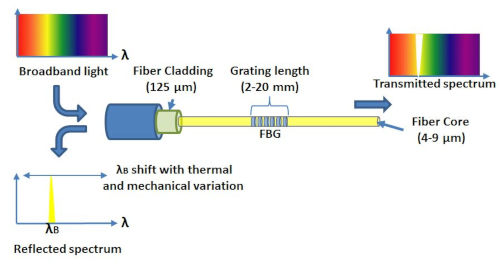
Figure 1. The FBG array sensor operating concept. This figure has been modified from a previous publication4. Please click here to view a larger version of this figure.
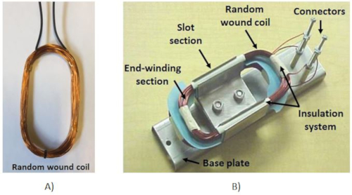
Figure 2. IEEE standard motorette coil assembly. (A) Random wound electric coil; see IEEE standards9. (B) Assembled and varnished IEEE standard motorette. Please click here to view a larger version of this figure.
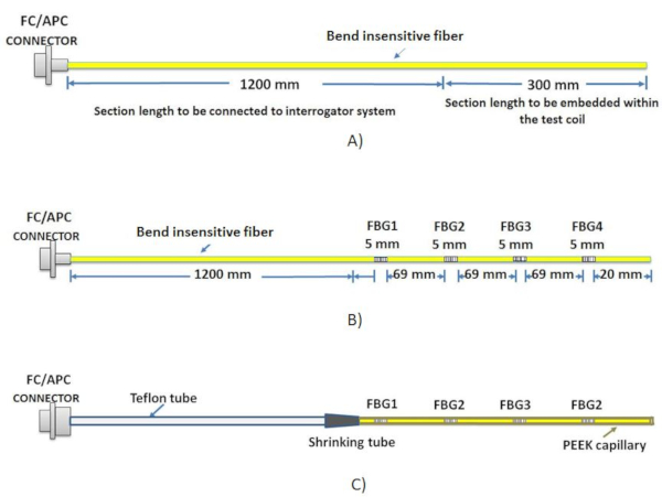
Figure 3. FBG thermal sensor array design. (A) FBG array fiber length, (B) FBG head locations in the array structure, (C) FBG array packaging design. Please click here to view a larger version of this figure.
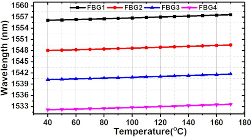
Figure 4. The packaged array sensor FBG heads calibration characteristics. The characteristics are derived from the data obtained in the array free thermal calibration tests. This figure has been modified from a previous publication4. Please click here to view a larger version of this figure.
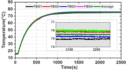
Figure 5. FBG array thermal measurements obtained in steady state thermal condition test. The individual head thermal measurements reported by the FBG array sensor are shown with an inset detail steady-state measurement view. This figure has been modified from a previous publication4. Please click here to view a larger version of this figure.
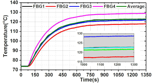
Figure 6. Thermal measurements in the non-uniform thermal condition test. This figure has been modified from a previous publication4. Please click here to view a larger version of this figure.
| Intercept | B1 | B2 | Statistics | ||||
| Value | Standard Error | Value | Standard Error | Value | Standard Error | Adj. R-Square | |
| FBG1 | 1555.771 | 0.0137 | 0.00855 | 2.85E-04 | 1.50E-05 | 1.34E-06 | 0.99978 |
| FBG2 | 1547.669 | 0.0112 | 0.00851 | 2.34E-04 | 1.41E-05 | 1.10E-06 | 0.99985 |
| FBG3 | 1539.852 | 0.0101 | 0.00871 | 2.11E-04 | 1.30E-05 | 9.90E-07 | 0.99988 |
| FBG4 | 1531.768 | 0.0131 | 0.00808 | 2.72E-04 | 1.67E-05 | 1.28E-06 | 0.9998 |
Table 1: Calculated polynomial qudratic fit curve parameters. The calculated parameters standard error and individual head correction coefficientsare included; good linearity and a coorection factor coefficient in excess of 0.999 was observed for the four tested FBG heads. This table has been modified from a previous publication4.
Discussion
The paper has demonstrated the procedure required to design, calibrate and test in situ FBG thermal sensors in low voltage wound coils. These sensors offer a number of advantages for in situ sensing applications within current carrying wound coil structures: they are fully EMI immune, are flexible and can conform to an arbitrary desired geometry to deliver arbitrary desired sensing point locations with high accuracy, and can provide a large number of sensing points on a single sensor. While thermal sensing within wound coils can be achieved with conventional thermal monitoring techniques employing thermocouple or resistance temperature detectors, the application of FBGs is shown to provide a number of attractive functional advantages.
Appropriate packaging of the FBG array sensor is key to its effective utilization. It is important that individual sensing heads or the entire sensing area of the fiber be appropriately packaged to ensure isolation of FBG heads from mechanical excitation in a rigid yet flexible thermally conductive capillary. It is desirable for the capillary to be designed of non-electrically conductive material as this ensures optimal performance in the EMI rich environment characteristic of current carrying coils.
Care needs to be taken during the process of packaging capillary installation into the coil to accurately position the package segments in their corresponding sensing locations. It is also essential to optimize the capillary geometry in case highly dynamic thermal conditions are to be observed.
It is vital to ensure accurate characterization of the coil embedded sensor. This is best done by performing free packaged sensor calibration before its installation within the wound coil geometry. While a high degree of protection from mechanical excitation is provided by the in situ packaging, the installation process can result in wavelength shift due to strain sensitivity. If performed carefully this can be negligible; however, it is good practice for this to be ascertained in in situ calibration tests where possible.
This application of FBGs within wound coils is relatively new and opens a number of opportunities for improved design, utilization, monitoring and health diagnosis of electrical machines. Further work is needed to reduce cost of these and make them a credibly viable option for large scale application in electric machinery.
Disclosures
The authors have nothing to disclose.
Acknowledgements
This work was supported by the UK Engineering and Physical Sciences Research Council (EPSRC) HOME-Offshore: Holistic Operation and Maintenance for Energy from Offshore Wind Farms Consortium under grant EP/P009743/1.
Materials
| Name | Company | Catalog Number | Comments |
| Cletop-S | Fujikura | 14110601 | Commercial optic connector cleaner |
| Copper wire AWG24 | RS | 357-744 | Commercial insulated copper wire |
| DC power supply | TTi | CPX400SP | Commercial 420W DC power supply |
| FBG sensors | ATGratings | NA | Commerically manufactured FBG array to design spec |
| Heat Shrink Tubing | RS | 700-4532 | Heat Shrink Tubing 3mm Sleeve Dia. x 10m |
| Kapton masking tape | RS | 436-2762 | Orange Masking Tape Tesa 51408 |
| PEEK tubing | Polyflon | 4901000060 | Commercial PEEK tubing |
| SmartScan04 | Smartfibres UK | S-Scan-04-F-60-U-UK | Commercial interrogator system |
| Thermal Oven | Lenton | WHT6/30 | Commercial thermal oven |
| Winder machine | RS | 244-2636 | Commercial winder machine |
References
- Stone, G. C., Boulter, E. A., Culbert, I., Dhirani, H. Electrical insulation for rotating machines-design, evaluation, aging, testing, and repair-Book Review. IEEE Electrical Insulation Magazine. 20 (3), 65-65 (2004).
- Mohammed, A., Djurović, S. Stator Winding Internal Thermal Monitoring and Analysis Using In Situ FBG Sensing Technology. IEEE Transactions on Energy Conversion. 33 (3), 1508-1518 (2018).
- Zhang, H. Online thermal monitoring models for induction machines. IEEE Transactions on Energy Conversion. 30 (4), 1279-1287 (2015).
- Mohammed, A., Djurović, S. FBG array sensor use for distributed internal thermal monitoring in low voltage random wound coils. 2017 6th Mediterranean Conference on Embedded Computing (MECO). , 1-4 (2017).
- Rao, Y. J. In-fibre Bragg grating sensors. Measurement Science and Technology. 8 (4), 355 (1997).
- Mohammed, A., Djurović, S. A study of distributed embedded thermal monitoring in electric coils based on FBG sensor multiplexing. Microprocessors and Microsystems. 62, 102-109 (2018).
- Lu, P., Men, L., Chen, Q. Resolving cross sensitivity of fiber Bragg gratings with different polymeric coatings. Applied Physics Letters. 92 (17), 171112 (2008).
- Mohammed, A., Djurović, S. FBG Thermal Sensing Features for Hot Spot Monitoring in Random Wound Electric Machine Coils. IEEE Sensors Journal. 17 (10), 3058-3067 (2017).
- IEEE. IEEE standard test procedure for thermal evaluation of systems of insulating materials for random-wound AC electric machinery. IEEE Std 117-2015. , 1-34 (2016).
- IEC. Rotating electrical machines - Part 1: Rating and performance. IEC. , (2010).
- Mohammed, A., Djurović, S., Smith, A. C., Tshiloz, K. FBG sensing for hot spot thermal monitoring in electric machinery random wound components. 2016 XXII International Conference on Electrical Machines (ICEM). , 2266-2272 (2016).
Reprints and Permissions
Request permission to reuse the text or figures of this JoVE article
Request PermissionExplore More Articles
This article has been published
Video Coming Soon
Copyright © 2025 MyJoVE Corporation. All rights reserved