Method Article
Calibration of Vector Network Analyzer for Measurements in Radio Frequency Propagation Channels
In This Article
Summary
This protocol describes best practices for calibrating a vector network analyzer prior to use as an accurate instrument, intended to measure components of a radio frequency propagation measurement test system.
Abstract
In situ measurements of radio frequency (RF) spectrum activity provide insight into the physics of radio frequency wave propagation and validate existing and new spectrum propagation models. Both of these parameters are essential to supporting and preserving interference-free spectrum sharing, as spectrum use continues to increase. It is vital that such propagation measurements are accurate, reproducible, and free of artifacts and bias. Characterizing the gains and losses of components used in these measurements is vital to their accuracy. A vector network analyzer (VNA) is a well-established, highly accurate, and versatile piece of equipment that measures both magnitude and phase of signals, if properly calibrated. This article details the best practices for calibrating a VNA. Once calibrated, it can be used to accurately measure components of a correctly configured propagation measurement (or channel sounding) system or can be used as a measurement system itself.
Introduction
The Institute for Telecommunication Sciences (ITS) is the research laboratory of the National Telecommunications and Information Administration (NTIA), an agency of the U.S. Department of Commerce. ITS has been active in radio propagation measurements since the 1950s. Spectrum sharing, the new paradigm for federal and commercial spectrum users, requires that two disparate systems share the same radio frequency spectrum at the same time. As spectrum sharing scenarios increase, so does the need for accurate and reproducible radio propagation measurements that provide a better understanding of the radio environment, which multiple services must share. The goal of the described procedure is to ensure that any components constituting such a system are well-characterized by an accurately configured VNA.
While demand for spectrum increases, it is not always possible to rapidly free spectrum that is currently used by federal agencies for commercial purposes. For example, in the Advanced Wireless Services (AWS)-3 band (1755–1780 MHz), spectrum sharing arrangements are being developed between military services and commercial wireless carriers1. These arrangements allow commercial wireless carriers to enter the AWS-3 band prior to completing the transition of military services out of the band.
The Defense Spectrum Organization (DSO) has been tasked with managing the AWS-3 transition. A key part of the transition involves developing new propagation models to evaluate the potential for RF interference between military and commercial wireless systems that share the band. The DSO has tasked ITS and others with performing a series of channel sounding measurements to build new models that better calculate the impact of foliage and man-made structures in the environment (collectively known as clutter). Improved propagation modeling that considers clutter will lead to fewer restrictions on commercial transmitters in the vicinity of military systems.
In situ measurements of RF spectrum activity provide insight into the physics of RF wave propagation and validate existing and new radio propagation models. Both of these components are essential to supporting and preserving interference-free spectrum sharing. Channel sounding techniques, in which a known test signal is transmitted from a specific location to either a mobile or stationary receiver, provide data that estimates radio channel characteristics in different environments. The data are used to develop and improve models that more accurately predict propagation losses or attenuation of the signal. These losses may be due to blocking and reflection by buildings and other obstacles (i.e., trees or terrain in urban canyons). These obstacles produce multiple, slightly variant, propagation paths resulting in signal loss or attenuation between the transmitting and receiving antenna.
ITS measurement techniques produce accurate, repeatable, and unbiased results. The DSO has encouraged ITS to share its institutional knowledge with the wider technical community. This knowledge includes how to optimally measure and process RF propagation data. The recently published NTIA Technical Memorandum TM-19-5352,3,4,5 describes a set of best practices for the preparation and verification of radio propagation measurement systems. As part of these best practices, a VNA is used to accurately measure the component losses or gains of a measurement system. The gains and losses are then used to calculate the signal attenuation between two antennas.
The protocol presented here addresses the best practices for calibrating a VNA5 prior to testing in laboratory or field applications. These include warm-up time, selection of RF connector type, making proper connections, and performance of appropriate calibration steps. Calibration should be conducted in a controlled lab environment prior to data collection in the context of a specific propagation measurement scenario. Additional considerations may be relevant to specific propagation measurement environments, which are outside the scope of this protocol.
The VNA is used to measure device characteristics of components and sub-assemblies when assembling other measurement systems. Power amplifiers, receivers, filters, low noise amplifiers, mixers, cables, and antennas are all components that can be characterized by a VNA. Prior to testing and/or calibrating a system, a list of all required components of the system is prepared, and all system components are assembled. Each component of a system is measured separately by inserting them between the VNA cables. This ensures that all components are operating within the manufacturer’s specifications. Once the components have been checked, the system is assembled, and losses throughout the entire system are measured. This ensures that reflections and transmissions between components are properly characterized.
A VNA measures scattering parameters (S-parameters), which are complex-valued quantities with both magnitude and phase. An S-parameter is a ratioed measurement of either the 1) reflected signal to the incident signal (reflection measurement) or 2) transmitted signal to the incident signal (transmission measurement). For a two-port device, four S-parameters (S11, S21, S12, and S22) can be measured. The first subscript refers to the port where the signal is received, and the second refers to the port where the signal is transmitted. Thus, S11 means the transmitted signal originated at port 1 and was received at port 1. Additionally, S21 means that the transmitted signal originated again at port 1 but is received at port 2. S11 measures the amount of signal that is reflected by the device under test (DUT) at port 1 with reference to the original signal that was incident at port 1. S21 measures the amount of signal that is transmitted through the DUT and arrives at port 2 with reference to the incident signal at port 1. S11 is a measure of the reflection coefficient of the DUT at port 1, and S21 is a measure of the transmission coefficient of the DUT from port 1 to port 2.
A calibration of the VNA is required to remove the systematic errors from components up to (and including) the measurement reference plane, which is typically at the end of the VNA measurement cables. A calibration removes system errors by measuring “perfect” known standards (open, shorts, loads, thru/line) and comparing it to the value that the VNA measures. Through a series of error corrections, a corrected value for the DUT is displayed. There are currently 12 error terms6,7 that are characterized during calibration. For more information, refer to original S-parameter measurements that were made on six-port network analyzers8 supported by classical microwave circuit theory9,10.
The most common types of S-parameter reflection measurements are return loss, standing wave ratio (SWR), reflection coefficient, and impedance matching. The most common types of S-parameter transmission measurements are insertion loss, transmission coefficient, gain/loss, group delay, phase or phase delay, and electrical delay. Transmission loss measurements are emphasized in the described protocol.
Measurement of gains and losses of system components using a VNA is well-understood. However, important steps are often skipped, such as cleaning connectors and using a proper torque wrench. This protocol provides all necessary steps and explanations of why some are particularly important. It will also serve as a prelude to a future article describing how to perform RF propagation measurements, including the calculations of signal attenuation.
Protocol
1. VNA set-up
- Gather all components of the propagation measurement system, including cables, amplifiers, filters, DUTs (which can be subassemblies) and other components.
- Turn on the VNA (Figure 1), and let it warm for at least 0.5 h to ensure that all internal components of VNA are a stable operating temperature and that phase drift is minimized.
- Press the Preset button.
- Attach high quality, phase-stable cables to ports 1 and 2 of the VNA (Figure 2).
- Tighten the connectors at the VNA ports with an 8 in.lbf. torque wrench. To properly torque a connection, hold the end of the handle and gently push the handle without allowing the handle to break all the way over.
- Visually inspect all cables and connectors for obvious signs of wear such as nicks, dents, and imperfect connector threads.
- Check the manufacturer’s specifications for valid measurement ranges for all cables, connectors, and DUTs. These specifications can include temperature, humidity, frequency, and power.
- Clean connectors on all devices and cable ends. Use swabs specifically designed for cleaning sensitive electronics and connectors. Using cables with dirty connectors can result in damaging the conducting surfaces of cables and produce inaccurate measurements.
- Dip a cotton swab into isopropyl alcohol.
- Gently clean the center conductor (Figure 3A) using the moistened swab. Do not exert too much force on the center conductor, as it is easily damaged.
- Clean the outer conductor of each connector (Figure 3B). Clean the coupling nut threads.
- Dry all cable and connector ends using clean compressed air (Figure 3C). If the compressed air cools the connector, allow the connector to return to room temperature (RT) before making and tightening all connections.
- Align and make connections between VNA cables on ports 1 and 2 and the DUT. Tighten with a 12 in.lb. torque wrench for type N connections (Figure 4). Ensure that the cable ends are properly aligned.
- Begin spinning the connector on the DUT side onto the VNA cable threads. Proper connections allow the nut to spin freely with little resistance. Resistance is a sign of cross-threading. Misalignment can damage the connector or cause signal reflections and signal loss. Do not overtighten connector, as this will damage the connector.
- Arrange the cables of the VNA such that they move minimally during calibration. Calibration cables are phase-stable and ideally not bent or moved during calibration.
- Adjust VNA measurement parameters according to the specifications of the DUT. The frequency range can also be selected using the center frequency and frequency range known as the “span”.
- Select the frequency range. Choose Stimulus Menu | Freq | Start Frequency: 1700 MHz. Choose Stimulus Menu | Freq | Stop Frequency: 1900 MHz.
- Select the measurement type (e.g., S11, S12, S21, S22). Choose Response Menu | Measure | S21.
- Select and adjust the port power. Choose Stimulus Menu | Power | Adjust Port Power: 0 dBm. Ensure that the output power is equal to (or below) the DUT maximum power specification.
- Select and adjust the sweep settings. Choose Stimulus Menu | Sweep | Sweep Type: Stepped. Choose Stimulus Menu | Sweep | time | Sweep Time: 1 sec. Then, choose Stimulus Menu | Sweep | Sweep Setup | Dwell Time: 0 μsec.
NOTE: A stepped sweep is the most accurate sweep type, as it steps to each frequency and dwells at a frequency before making a measurement. If using long cables, the dwell time may need to be increased to ensure that the signal arrives at the receiver after the measurement. A 0 μs dwell time is an optimal default setting. - Select and adjust averaging mode by choosing Response Menu | Averaging | Averaging: IFBW: 1 kHz.
NOTE: Choose the appropriate averaging type: “point averaging” averages each frequency point a number of specified times (i.e., 2, 4 16, 32, etc.), which reduces the noise floor and uncertainty but increases the sweep time. IFBW uses a filter to measure the power in a small bandwidth, which also reduces the noise floor but requires less measurement time. IFWB averaging tends to be a more optimal averaging technique. - Choose the displayed data format (e.g., LogMag [default setting], Smith Chart, SWR, etc.) by selecting Response Menu | Format | LogMag.
- Choose the number of data points in the displayed trace using Stimulus Menu | Sweep | Number of Points: 1601.
NOTE: The number of points is set so that maximal frequency coverage can be attained between the start and stop frequencies:

In the example above, the step size or frequency spacing is 0.125 MHz, so that frequency(1) = 1700.000 MHz, frequency(2) = 1700.125 MHz, … frequency(1600) = 1899.875 MHz, frequency(1601) = 1900 MHz.
2. Calibration of the VNA
- Choose a manual or electronic calibration, if an electronic calibration module is available and desired (see section 2.11). Either calibration is accurate.
- Choose Manual Calibration by selecting Response | Cal Menu | Start Cal | Calibration Wizard | Unguided.
- Choose the appropriate calibration kit so that an accurate value of the standards in the specific calibration kit are known (Figure 5). Here, choose 85054D, then choose the two-port short-open-load-thru (SOLT) calibration (for a DUT with two ports). Other available calibrations are a one-port for a device with a single port, in addition to a response calibration. The SOLT is the most accurate option11.
- Choose Next to go to the next screen.
- Attach an open calibration standard (Figure 6) to the cable attached to port 1. An open calibration standard has an open cavity behind the connector to simulate a free-space impedance of 377 Ω.
- Attach a short calibration standard to the cable attached to port 2. A short has a metal plate behind the connector so that the incoming voltage is completely reflected.
- Choose Port 1 | OPEN | Type N (50) female open, which performs a measurement of the attached open. A trace will appear on the VNA screen, gently sloping away from a 0 dB reference level on a S11, log-magnitude display format for the open standard. Once the measurement is complete (a check mark will appear above the standard), press the OK button to continue. This will send the user back to the previous screen.
- Choose a male or female calibration standard with the same sex connector as that of the DUT (i.e., a male calibration standard has the center pin, and a female calibration standard will have an insertable port). Older VNAs require a calibration standard based on the sex of the VNA cable.
- Choose Port 2 | SHORT | Type N (50) female short, which performs a measurement of the attached short. A trace will appear on the VNA screen, gently sloping away from a 0 dB reference level on a S11, log-magnitude display format for the short standard. Once the measurement is complete (a check mark will appear above the standard), press the OK button to continue. This will send the user back to the previous screen.
- Swap calibration standards between ports (i.e., attach the open calibration standard to port 2, then attach the short calibration standard to port 1).
- Choose Port 1 | SHORT | Type N (50) female short to measure the short on port 1. A trace will appear on the VNA screen, gently sloping away from a 0 dB reference level on a S11, log-magnitude display format for the short standard. Once the measurement is complete (a check mark will appear above the standard), press the OK button to continue. This will send the user back to the previous screen.
- Choose Port 2 | OPEN | Type N (50) female open to measure the open on port 2. A trace will appear on the VNA screen, gently sloping away from a 0 dB reference level on a S11, log-magnitude display format for the open standard. Once the measurement is complete (a check mark will appear above the standard), press the OK button to continue. This will send the user back to the previous screen.
- Remove the short from port 1 and place a broadband load on port 1. A load absorbs the incoming energy, which results in a small reflection over a large range of frequencies.
- Choose Port 1 | LOADS | Type N (50) broadband load to measure the load on port 1. Once the measurement is complete (a check mark will appear above the standard), press the OK button to continue. This will send the user back to the previous screen.
- Keep the current calibration standard on port 2. Do not leave the port open, as it may provide a path for leakage signals. A trace will appear on the VNA screen and vary across the screen. All measured values on a S11, log-magnitude display format will be less than -20 dB for a good load.
- Remove the open from port 2, take the broadband load from port 1, and place the broadband load on port 2. Place the open from port 2 on port 1 to prevent leakage signals.
- Choose Port 2 | LOADS | Type N (50) broadband load to measure the load on port 2. A trace will appear on the VNA screen and vary across the screen. All measured values on a S11, log-magnitude display format will be less than -20 dB for a good load. Once the measurement is complete (a check mark will appear above the standard), press the OK button to continue. This will send the user back to the previous screen.
- Insert a thru calibration standard between the cables attached to ports 1 and 2. This is typically an adapter with the same sex connectors on both ends.
- Choose THRU to measure the thru calibration standard. Once the measurement is complete, a check mark will appear above the THRU standard on this screen.
NOTE: The isolation measurement can typically be omitted during calibration as isolation measures the crosstalk between cables and its value is often very small compared to other standards. The calibration measurements above can be done in any order.
- Choose THRU to measure the thru calibration standard. Once the measurement is complete, a check mark will appear above the THRU standard on this screen.
- Once all standards have a check mark above them, save the calibration. Choose Next | Save as User Calset. Enter a name for the calibration and press the SAVE button.
- Check the calibration as detailed in section 3.
- If a manual calibration is not chosen, choose the electronic calibration option12. Attach the electronic calibration kit (Figure 7) to the cables between ports 1 and 2. Select Response | Cal Menu | Start Cal | Calibration Wizard | Electronic Calibration with the electronic calibration option.
- Choose 2-port ECal | Next, then select the Measure button. The electronic calibration module will automatically measure a number of different standards and prompt the user to save the calibration at the end.
- Choose Next | Save as User Calset. Enter a name for the calibration and press the SAVE button.
NOTE: For an electronic calibration only the cables from ports 1 and 2 are connected to the module. All calibration standards are contained in the module. The electronic calibration will calibrate the internal standards automatically. If the electronic calibration module does not have the same connector types as the cables, then an additional calibration will need to be completed to modify the calibration error corrections contained within the module to account for the adapters. Make sure to check with the manufacturer for guidance.
3. Checking the calibration
- Use a thru to check the calibration.
- Connect a thru adapter (Figure 6) without obvious signs of wear to the cables between ports 1 and 2. Do not measure the thru standard. Choose a different thru.
- Choose Response | Measure | S21, then Response | Scale | Scale. Set the Per Division value to 0.1 by pressing the down arrow button. Choose Stimulus Menu | Trigger | Single to measure the insertion loss of the thru. A single sweep will appear across the frequency range.
NOTE: The value of the thru on a log magnitude plot lies within 0.05 dB of the 0 dB reference (Figure 8) for sufficient calibration. This is an empirical value obtained over many years of calibrations. This can be seen by changing the scale to 0.05 dB per division. - Once the thru has been checked, return the scale back to 10 dB/division by choosing Response | Scale | Scale and set the Per Division value to 10. Choose Response | Measure | S11.
- Choose Stimulus Menu | Trigger | Single to measure S11. The value of a good thru is the following: |S11| = -20 dB (1% reflection in power and 10% reflection in voltage).
NOTE: The Smith Chart13 representation displays impedance. Measurements of S11 and S22 appear as a small circle in the center of the chart. The impedance value is within 0.5 Ω from the 50 Ω reference for sufficient calibration.
- Use a 50 Ω load to check the calibration.
- Attach a 50 Ω matched load to the port 1.
- Choose Stimulus Menu | Trigger | Single to measure S11.
NOTE: A matched load is less than -20 dB (the reflection coefficient of an ideal load is 0). This will also appear as a small circle at the center of the Smith Chart (Figure 9).
- Use an open calibration standard to check the calibration.
- Connect an open calibration standard.
- Choose Stimulus Menu | Trigger | Single to measure S11. An open is 0 dB on a log-magnitude plot (the reflection coefficient of an ideal open is 1). On a Smith Chart, the open appears as a small circle at 0 on the far right (Figure 9) for sufficient calibration.
- Use a short calibration standard to check the calibration.
- Connect a short calibration standard.
- Choose Stimulus Menu | Trigger | Single to measure S11. A short is 0 dB (the reflection coefficient of an ideal short is -1) on the log-magnitude plot. On the Smith Chart, the value appears as a circle on the far left (Figure 9) for sufficient calibration.
NOTE: If a calibration test fails, check the connections and repeat the calibration. If the calibration is good, continue to section 4.
4. Measurement of components or system losses
- Connect the DUT to the VNA. If the DUT has more than two ports (i.e., switches, power dividers, etc.), attach 50 Ω matched loads to the ports that are not connected to the VNA, as power will be reflected from these ports and change the measurement.
- Select Response | Measure | S21.
- Select Stimulus Menu | Trigger | Single to measure the DUT.
- Select File | Save Data As… . Type in a file name in the file name box. Choose a file type of either .CSV or Trace (*.s2p). Choose the Scope (the default value of Displayed Traces is appropriate here). Choose a Format (e.g., log magnitude and angle, linear magnitude and phase, real and imaginary, and displayed format [such as a Smith Chart]). Press SAVE to save the data.
- Check and analyze the test results of a bandpass filter. An example is outlined in the following steps.
- Identify parts of the trace by placing markers on the trace. Select Marker/Analysis | Marker | Marker 1 and press OK.
- Select Marker/Analysis | Marker Search | Max to find the insertion loss of the trace filter. The knob on the front panel can also be used to identify maxima and minima while sweeping the marker across frequency points.
- Select Marker/Analysis | Marker < Marker 1, then select delta marker and coupled markers. The value of this marker as shown on the screen should read 0 dB. This will set a reference value for the other markers.
- Select Marker/Analysis | Marker… | Marker 2 | ON | coupled markers. Click inside the stimulus box to highlight the frequency, then move the knob until the reading of Marker 2 on the screen shows -3 dB.
- Select Marker/Analysis | Marker… | Marker 3 | ON | coupled markers. Click inside the stimulus box to highlight the frequency and move the knob until the reading of Marker 3 on the screen shows -3 dB.
- Compare the measured values to those of the manufacturer’s filter specifications.
Results
When verifying whether a component is operating correctly, it is important to consult the manufacturer’s specifications, which can be found on their respective websites. Here, the filter (Figure 10) was measured after consulting its specifications14. As shown in Figure 11, the insertion loss was identified, as well as the 3 dB points. The measured insertion loss after calibration, as shown by marker 1, had a magnitude of 0.83 dB. The negative sign indicates that it was a loss. The insertion loss in the reference is specified to be 0.8 dB adjusted (dBa). The measured 3 dB bandwidth of the filter changed from 1749 MHz to 1854 MHz. When subtracted, this yielded a value of 105 MHz, which is close to the typical value of 104.5 MHz.
There are 10 dB attenuators built to withstand an input power of 50 W, as described by the manufacturer’s specifications15. The attenuation specification for this attenuator is 10 dB ± 0.5 dB. At some point, an input power greater than 50 W was input into the attenuator, which damaged the attenuator. A calibrated VNA was used to check the quality of this component. Again, it is important to measure each component before all field measurements for quality assurance. Measurement of the DUT is shown in Figure 12. In comparison, measurement of a good 10 dB attenuator is shown in Figure 13. It should be noted that the measured value was 9.88 dB at 1750 MHz, which is within the specified range of -9.5 to -10.5 dB across the entire bandwidth of 1700–1900 MHz.
Finally, cable loss is another important measurement frequently performed in radio frequency measurements. Specifications for the measured cable can be found on page 5 of the data sheet16. The attenuation per foot (dB/ft) was 0.05 dB at 1 GHz, or 0.16 dB/m. A measured cable with a length of 36 feet/11 m had a specified loss of ~1.8 dB, according to the manufacturer. The measured loss is shown in Figure 14. At a frequency of 1750 MHz, the measured loss was -1.88 dB (which, when rounded up to the nearest tenth of a decibel, is a magnitude of 1.9 dB).
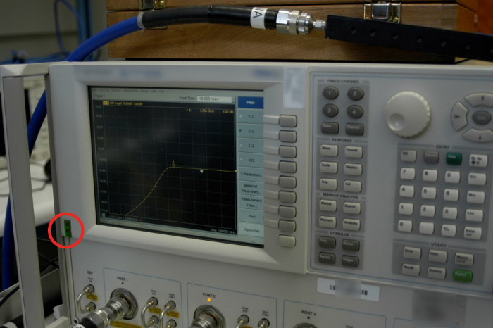
Figure 1: Turning on the VNA. The red circle represents the location of the VNA power button. Please click here to view a larger version of this figure.
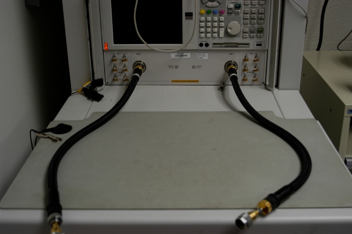
Figure 2: High quality, phase-stable cables attached to two VNA ports. The cables are attached to the front panel of the VNA using an 8 in.lbf. torque wrench. Please click here to view a larger version of this figure.
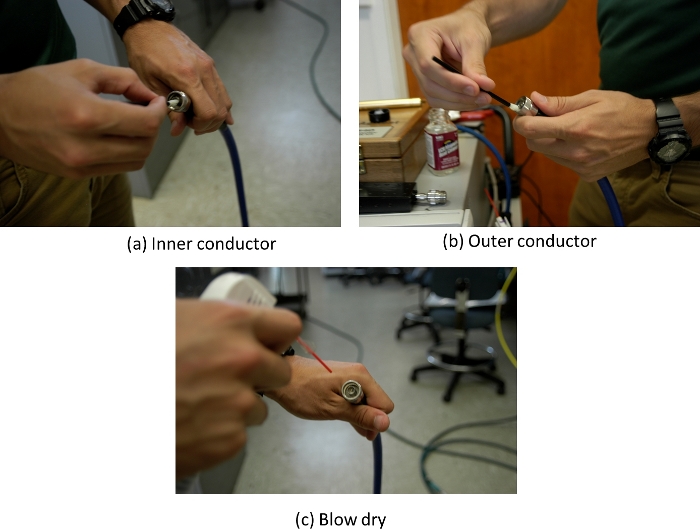
Figure 3: Cleaning connectors. (A) Cleaning of the inner conductor, (B) cleaning of the outer conductor and threads, and (C) gently blow drying the connector using compressed air. Please click here to view a larger version of this figure.
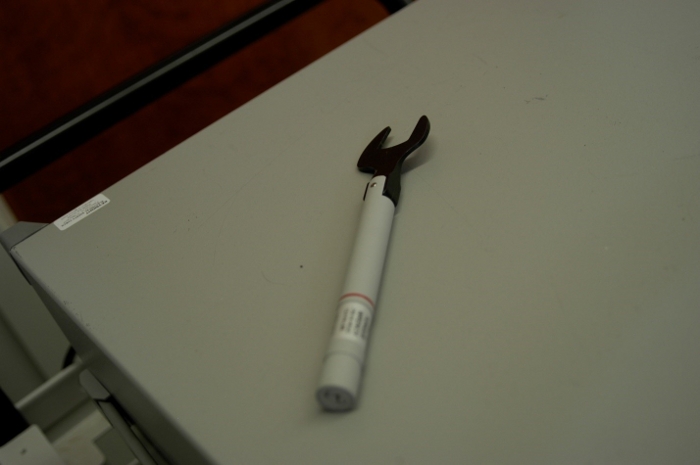
Figure 4: A 12 in.lbf. torque wrench for type N connectors. This wrench is used to tighten connections between the VNA cables and DUT. Please click here to view a larger version of this figure.
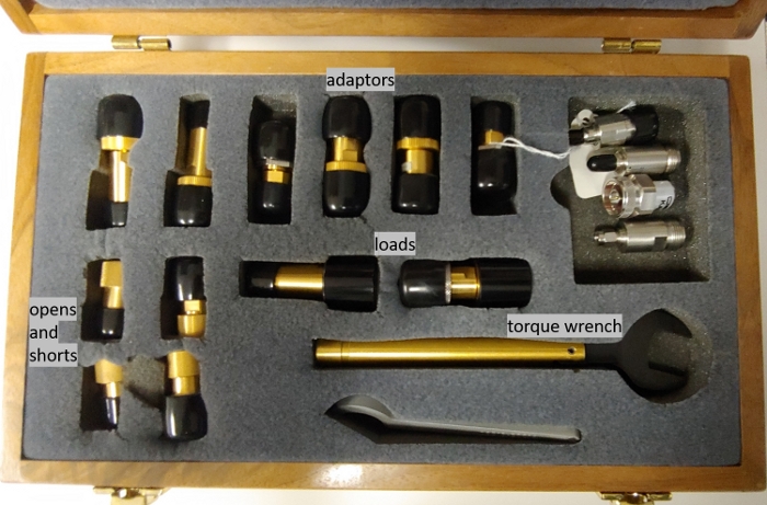
Figure 5: Type N calibration kit. Shown here is a calibration kit containing open, short, load, and thru standards used to calibrate errors in the VNA. Please click here to view a larger version of this figure.
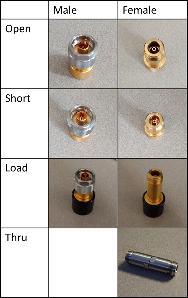
Figure 6: Type N calibrations standards. Photographs of the male and female calibration standards used in the calibration. Please click here to view a larger version of this figure.
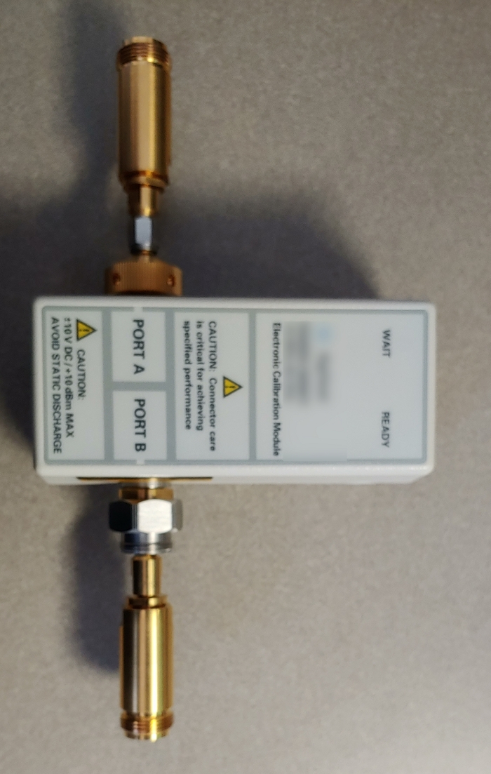
Figure 7: Electronic calibration module. A photograph of an electronic calibration module. Please click here to view a larger version of this figure.
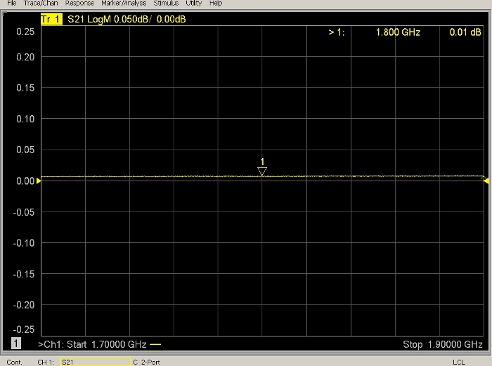
Figure 8: Thru calibration check after calibration on a log-magnitude plot as a function of frequency in GHz. The value of the thru is 0.01 dB at a frequency of 1.8 GHz. This shows the value of the thru as a function of frequency in GHz after calibration. The thru is used as a calibration check to ensure that the calibration is valid. Please click here to view a larger version of this figure.
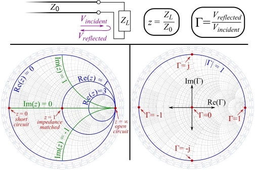
Figure 9: Smith Chart explanation. Real and imaginary impedance value locations for standard impedances are shown in the left-hand figure, and impedance magnitude values are shown in the right-hand figure17. This Smith Chart drawing shows both the real and imaginary impedance on the left and impedance magnitude on the right. Please click here to view a larger version of this figure.
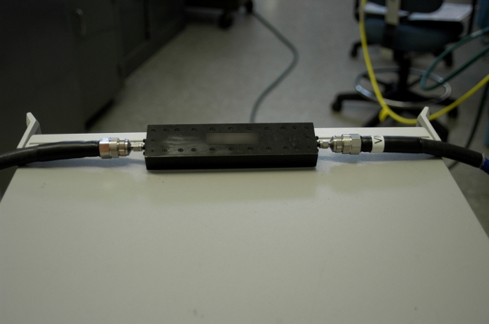
Figure 10: RF filter inserted between ports 1 and 2. A photograph of an RF filter inserted between ports 1 and 2 at the end of the VNA cables during measurements. Please click here to view a larger version of this figure.
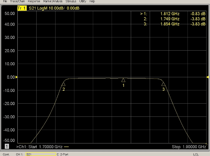
Figure 11: Measured insertion loss and 3 dB points for RF filter with specifications provided in Figure 9. This is a screenshot from the VNA during measurement of the RF filter that is shown in Figure 10. Please click here to view a larger version of this figure.
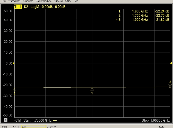
Figure 12: Measurement of 10 dB attenuator not within its specifications. The measured value is -22.70 dB at 1.7 GHz and its specification is 10 dB ± 0.5 dB. Also shown is measurement of a 10 dB attenuator that is no longer within its specifications. Please click here to view a larger version of this figure.
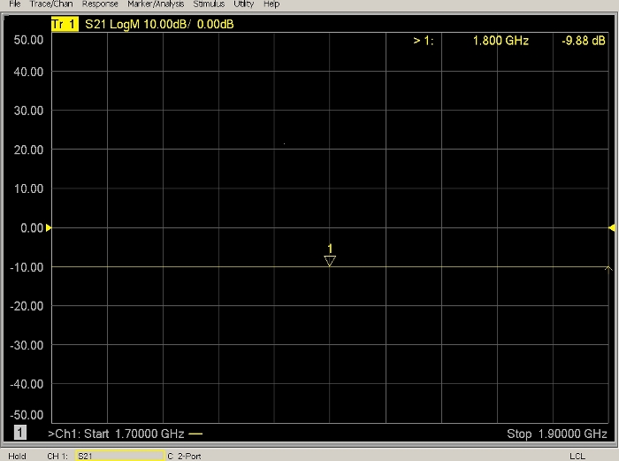
Figure 13: Measurement of 10 dB attenuator within its specifications. The measured value was -9.88 dB. Also shown is measurement of a 10-dB attenuator that is within its specifications. Please click here to view a larger version of this figure.
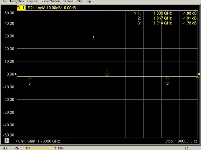
Figure 14: Measurement of 36 ft (11 m) coaxial cable with a 0.05 dB/ft specified attenuation value. Loss through the length of the cable was expected to be ~1.8 dB, which is consistent with the measured value of -1.9 dB at 1.87 GHz. Also displayed is measurement of a cable showing that the measured loss is within the manufacturer’s specifications. Please click here to view a larger version of this figure.
Discussion
It is important to allow the VNA to warm to RT for at least 0.5 h (although, 1 h is better) before calibrations are performed, which allows all internal components to come to RT and results in more stable calibrations. One calibration can last several days without a large loss of accuracy; however, the calibration is checked daily using a calibration standard to ensure integrity of the measurement. Inspection of all system components is essential so that bad connectors do not damage the precision of the VNA. It is best to use low loss cables with the VNA. The integrity of the calibration must be checked before the measurement of any system component or DUT. Any measurement outside the specifications provided here should be repeated or may require a new calibration. Finally, using the manufacturer’s specifications to check the measured DUT values is a necessary part of validation.
Using the VNA as a measuring instrument has its limitations. If the DUT or system has losses so large that the measured S-parameters fall below the noise floor of the VNA, it cannot be measured with the VNA. It is possible to lower the noise floor by decreasing the IF bandwidth and increasing the sweep time. This will slow down the measurement acquisition time; thus, there is a trade-off when adjusting these parameters. The VNA cannot handle input powers greater than 30 dBm, so using internal or external attenuation when measuring amplifiers is required. The VNA has a source and receiver located in the same instrument, so it has been used as a radio propagation measurement system. Because the source and receiver are located in the VNA, the transmitting port must be joined in some manner to the receiving port. Typically, this is done with cables; however, cables add loss, decreasing the dynamic range of what can be measured. Furthermore, separation distances become limited.
The other method by which losses can be measured is use of a signal generator and power meter. The power meter is a scalar measurement device, so it can only measure a signal’s magnitude. It cannot monitor the phase of the signal, which results in less accurate measurements of the signal. The VNA measures both the magnitude and phase (of real and imaginary components) of a measured signal relative to a well-known input signal, which is a higher quality measurement.
VNAs are a versatile option for many types of measurements. The instrument can be used to measure radiated radio signals using antennas on the transmitting and receiving ports18. Time domain analysis can be used to monitor signals over time and determine where a break occurs in a cable. It can measure many frequencies during a sweep, which can be used to understand attenuation losses over many frequencies either in a conducted19 or radiated environment20. Understanding the various parameter settings of the VNA results in well-characterized DUTs/systems, and measurements obtained with the DUT/system can be used with a high degree of confidence.
Disclosures
The authors have nothing to disclose.
Acknowledgements
We thank the Defense Spectrum Office (DSO) for funding this work.
Materials
| Name | Company | Catalog Number | Comments |
| 12 inch-pound torque wrench | Maury Microwave | TW-12 | |
| 8 inch-pound torque wrench | Keysight Technologies | 8710-1764 | |
| Attenuators | Mini-Circuits | BW-N10W50+ | |
| Cable 1 | Micro-Coax | UFB311A – 36 feet | |
| Calibration Standard Set (1) (manual) | Keysight Technologies | Economy Type-N Calibration kit, 85054 D | |
| Calibration Standard Set (2) (E-cal) | Agilent Technologies | Electronic Calibration Kit, N4693-60001, 10 MHz to 50 GHz | |
| Cleaning Swab | Chemtronics | Flextips Mini | |
| Compressed Air | Techspray | Need ultra filtered | |
| Filter 1 | K&L Microwave, Inc. | 8FV50-1802-T95-O/O | |
| Isopropyl Alcohol | Any brand | ||
| VNA | Keysight Technologies | There are many options available for a researcher – please consult the website |
References
- Commerce Spectrum Management Advisory Committee. . 1755-1850 MHz Airborne Operations: Air Combat Training System Sub-Working Group Final Report. , (2014).
- Hammerschmidt, C. A., Johnk, R. T., McKenna, P. M., Anderson, C. R. Best Practices for Radio Propagation Measurements. U.S. Dept. of Commerce. , (2018).
- Molisch, A. . Wireless Communications - 2nd edition. , (2010).
- Anderson, C. R. . Design and Implementation of an Ultrabroadband Millimeter-Wavelength Vector Sliding Correlator Channel Sounder and In-Building Multipath Measurements at 2.5 & 60 GHz. , (2002).
- Kerns, D. M., Beatty, R. W. . Basic Theory of Waveguide Junctions and Introductory Microwave Network Analysis (Monographs on Electromagnetic Waves). , (1967).
- Engen, G. F. . Microwave Circuit Theory and Foundations of Microwave Metrology. , (1992).
- Witte, R. A. . Spectrum and Network Measurements. , (2001).
- Jargon, J. A., Williams, D. F., Hale, P. D. Developing Models for Type-N Coaxial VNA Calibration Kits within the NIST Microwave Uncertainty Framework. 87th ARFTG Microwave Measurement Conference. , (2016).
- Keysight Electronic Calibration Modules. Keysight Technologies Available from: https://literature.cdn.keysight.com/litweb/pdf/N7550-90002.pdf?id=2852836 (2019)
- Smith, P. H. . Electronic Applications of the Smith Chart. , (2006).
- . Utiflex Flexible Microwave Cable Assemblies Brochure Available from: https://rf.cdiweb.com/datasheets/micro-coax/UtiflexCableAssemblies.pdf (2019)
- . Smith Chart Explanation Available from: https://commons.wikimedia.org/wiki/File:Smith_chart_explanation.svg (2019)
- Camell, D., Johnk, R. T., Novotny, D., Grosvenor, C. Free-Space Antenna Factors through the Use of Time-Domain Signal Processing. IEEE Intl. Symp. Electromag. Compat. , (2007).
- Baker-Jarvis, J., Janezic, M. D., Krupka, J. Measurements of Coaxial Dielectric Samples Employing Both Transmission/Reflection and Resonant Techniques to Enhance Air-Gap Corrections+. Intl. Conf. Microw., Radar & Wireless Communications. , (2006).
- Grosvenor, C., Camell, D., Koepke, G., Novotny, D., Johnk, R. T. Electromagnetic Airframe Penetration Measurements of a Beechcraft Premiere 1A. NIST Technical Note 1548. , (2008).
Reprints and Permissions
Request permission to reuse the text or figures of this JoVE article
Request PermissionThis article has been published
Video Coming Soon
Copyright © 2025 MyJoVE Corporation. All rights reserved