Method Article
板料成形过程的知识基于云的有限元模拟
摘要
The following paper presents a novel FE simulation technique (KBC-FE), which reduces computational cost by performing simulations on a cloud computing environment, through the application of individual modules. Moreover, it establishes a seamless collaborative network between world leading scientists, enabling the integration of cutting edge knowledge modules into FE simulations.
摘要
The use of Finite Element (FE) simulation software to adequately predict the outcome of sheet metal forming processes is crucial to enhancing the efficiency and lowering the development time of such processes, whilst reducing costs involved in trial-and-error prototyping. Recent focus on the substitution of steel components with aluminum alloy alternatives in the automotive and aerospace sectors has increased the need to simulate the forming behavior of such alloys for ever more complex component geometries. However these alloys, and in particular their high strength variants, exhibit limited formability at room temperature, and high temperature manufacturing technologies have been developed to form them. Consequently, advanced constitutive models are required to reflect the associated temperature and strain rate effects. Simulating such behavior is computationally very expensive using conventional FE simulation techniques.
This paper presents a novel Knowledge Based Cloud FE (KBC-FE) simulation technique that combines advanced material and friction models with conventional FE simulations in an efficient manner thus enhancing the capability of commercial simulation software packages. The application of these methods is demonstrated through two example case studies, namely: the prediction of a material's forming limit under hot stamping conditions, and the tool life prediction under multi-cycle loading conditions.
引言
Finite Element (FE) simulations have become a powerful tool for optimizing process parameters in the metal forming industry. The reliability of FE simulation results is dependent on the accuracy of the material definition, input in the form of flow stress data or constitutive equations, and the assignment of the boundary conditions, such as the friction coefficient and the heat transfer coefficient. In the past few years, advanced FE simulations have been developed via the implementation of user-defined subroutines, which have significantly broadened the capability of FE software.
The use of such advanced FE simulations in the design of forming processes for structural components has been investigated by both the aviation and automotive industries, with the intention of producing lightweight structures that reduces operating costs and CO2 emissions. Particular focus has been placed on the replacement of steel components with lower density materials, such as aluminum alloys and magnesium alloys. However, these alloys, especially the stronger variants, offer limited formability at room temperature and thus complex-shaped components cannot be manufactured using the conventional cold stamping process. Therefore, advanced high temperature forming technologies, such as warm aluminum forming 1-4, hot stamping of aluminum alloys 5-9 and hot stamping of high strength steels 10, have been developed over the past decades to enable complex-shaped components to be formed. In general, high temperature forming processes involve significant temperature variations, strain rate and loading path changes 11, which would, for instance, cause inevitable viscoplastic and loading history dependent responses from the work piece materials. These are intrinsic features of high temperature forming processes and may be difficult to represent using conventional FE simulation techniques. Another desirable feature would be the ability to predict the tool life over multiple forming cycles in such processes, since they require low friction characteristics achieved through coatings that degrade with each forming operation. To represent all these features via the implementation of user-defined subroutines would be computationally very expensive. Moreover, the development and implementation of multiple subroutines would require excessive multi-disciplinary knowledge from an engineer conducting the simulations.
In the present work, a novel Knowledge Based Cloud FE (KBC-FE) simulation technique is proposed, based on the application of modules on a cloud computing environment, that enables an efficient and effective method of modeling advanced forming features in conjunction with conventional FE simulations. In this technique, data from the FE software is processed at each cloud module, and then imported back into the FE software in the relevant consistent format, for further processing and analysis. The development of these modules and their implementation in the KBC-FE is detailed.
研究方案
1.高温成形极限预测模型的建立
- 激光切割试样从铝合金AA6082薄板成形性的测试(1.5毫米厚)到选定的几何结构12。
- 刻蚀使用电解方法13的网格图案,具有1毫米的正常间距的0.75毫米直径的圆形点组成,样品的表面上。
- 手动应用石墨润滑脂作为对非蚀刻侧的润滑剂。
- 组装圆顶试验台在高速率液压机12。使用一个250千牛顿液压万能试验机。
- 升温圆顶试验装置到测试温度和设定在一个恒定的移动速度的冲头。然后启动测试。
注意:测试温度是300,400,和450℃,分别。测试速度包括75,250,和400毫米/秒。 - 停止测试在缩颈的第一次出现。
注:按strokE( 即,最终试样高度)被设定为使得缩颈只是上所形成的样品观察到的。 - 测量使用一个高度测量最终样品的高度,并计算使用光学三维成型分析系统的应变和最大应变率(相对于时间的应变的变化率)。分析在网格间距的变化来计算菌株在形成试样的各点。
- 确保光学三维成型分析系统包括一个摄像头,所形成的样品和校准刻度杆14。
注:样品被放置在一个转台的中心,并包含与比例尺,并且它们的相对位置保持固定用于分析的持续时间。 - 设置相机以固定的海拔高度( 如 50厘米)和角度( 例如,30,50,或70°)的试件,并拍照在转盘的一个完整旋转(360度),在15°的增量。
注意:在present的工作中,来自多个摄像机的海拔和角度,以便将菌株在整个试样15映射获得三组图像。 - 加载图像到光学三维成形分析软件,并继续计算的应变。通过点击"计算椭圆和捆绑"功能,可检测网格点,之后点击"计算3D点和网格"功能,建立了网格做到这一点。
注:计算应变和评估模式进行可视化。 - 输出应变分布来确定基于ISO 12004 16每个样品的极限应变,并绘制成形极限图的不同形成的速度和成形温度。
- 在不同的温度从300至500℃,应变速率校准为AA6082材料模型从0.1到10秒-1。
注:材料模型及其AA6082常数在参考17中详细介绍。 - 实施和统一Hosford各向异性屈服功能18,Marciniak-库琴斯基(MK)理论19和步骤1.12材料模型转化成积分算法,从而制订成形极限预测模型。
注意:该模型中参照图11进行说明。 - 校准和使用步骤1.11获得的实验结果验证了开发的模型步1.13。
- 从步骤1.14预测通过验证模型11成形极限。
注意: 图1示出在不同温度下所得到的模型预测,在250毫米/秒的成膜速度,或等同地,6.26秒的应变速率-1。
2.交互式摩擦/磨损模型的建立
- 执行球上盘测试涂层(盘)的标本
- 准备氮化钛(TiN)对轴承钢化涂料使用阴极弧中频磁控溅射,在参考20中给出的沉积参数GCr15钢盘。
- 使用扫描电子显微镜(SEM),得到涂覆样品的表面/剖面外形。通过比较基地和涂层材料的形貌(亮度和合同)测量通过SEM图像在TiN涂层厚度。
注意:实验程序可以在参照图20中找到。 - 使用白色光间ferometric表面亲filometer以获得样品的表面粗糙度。将样品镜头下,调整显微镜获得清晰的表面结构。照亮样品和调整x的角度和y轴来观察清晰的干扰条带(其可以从屏幕上进行监视)。在软件中设置的总深度并开始测量。自动扫描样品表面和计算表面粗糙度。
- 评估粘附强度ØF使用一个微划痕测试样品。应用不断增加的负载(最大50 N),并在TiN涂层刮距离(最多5毫米)。确定该涂层的临界负荷造成故障,将获得的微划痕曲线20。
- 评估用硬度压头对试样的硬度。应用的20 N的静荷载对样品15秒。测量对角线印象由压头制成的,然后获得从测试仪的硬度值。
- 进行球 - 盘测试上的摩擦计在周围环境(温度25℃,湿度30%)。使用一个6毫米直径的WC-6%球(微硬度1,780 HV,磨损强度1380牛顿/厘米,弹性模量71 GPA)作为对涂覆的光盘相对应。调整相对滑动速度至5毫米/秒。应用200 N的正常负荷使用摩擦磨损试验机,启动电机和记录摩擦值。中断测试在180秒,350秒,400秒,和450秒,分别使用邻来分析磨痕ptical显微镜20。
- 测量磨损表面的使用测试之后白光干涉表面轮廓地形。
- 重复用不同的载荷时的测试(步骤2.1.6)(300 N,400 N)。
- 确定摩擦系数的演变,直到硬涂层的破裂,其特征在于,在所述摩擦系数的急剧增加
- 绘制的摩擦系数与时间的演进步骤2.1.6记录摩擦值后。
注:摩擦系数的演变示于参考20。 - 评估摩擦系数的演变中的磨损性能方面和相关的机制。
注:摩擦的演变的特征为三个不同的阶段:(ⅰ)低摩擦阶段,(ⅱ)耕作摩擦阶段,和(iii)涂覆击穿阶段20,21。 - 评估穿S通过在180秒tates手动中断测试,然后分析使用光学显微镜的磨痕。
注意:此步骤是在步骤2.2.2所述来调查对于低摩擦阶段的磨损碎屑。 - 在350秒,400秒和450秒,分别重复步骤2.2.3。
- 绘制的摩擦系数与时间的演进步骤2.1.6记录摩擦值后。
- 开发交互式摩擦模型
- 由初始摩擦μα与硬件颗粒μPc的犁地摩擦结合表征整体摩擦系数μ(如图式(1))20。
(1)
- 用瞬涂层厚度(h)结合的球和基底(μPS)之间的耕作摩擦到犁摩擦μPc的涂层击穿引起的急剧升高的模型(公式(2))。
注意:在这种情况下,μPC等于μ 诗当剩余涂层厚度是零(表示硬质被膜的完全崩溃)。
(2)
其中,λ1和λ2是引入来表示的磨损过程的物理意义模型参数。 λ1描述大截留磨损粒子的影响,和λ2表示的犁地摩擦效应,其特征是由摩擦系数的斜率的强度。 - 使用基于时间的积分算法,以获得剩余的涂层厚度的演变和不同接触条件下的累积磨损建模。更新由公式每次计算循环中的涂层厚度。 (3)。
(3)
其中h 0是初始涂层厚度并且是该涂层的时间相关的磨损率。 - 修改Archard的穿法22(式(4))在本模式实现它。
(4)
其中K是磨损系数,P是接触压力,v是滑动速度,和H c是涂层和基材的组合硬度。 - 使用Korsunsky的模型来计算合并的硬度(等式(5))。
(5)
其中H s是基材的硬度,α是涂层和基体和β之间的硬度比为厚度的影响系数。 - 表示由功率微升负载相关的参数λ1和KAW方程。
(6)
(7)
其中,κλ1,κK,Νλ1和ΝK分别与摩擦20的进化材料常数。 - 适合交互式摩擦模型使用作者的组中开发了一种积分算法来确定模型参数的实验结果。
- 由初始摩擦μα与硬件颗粒μPc的犁地摩擦结合表征整体摩擦系数μ(如图式(1))20。
3. KBC-FE模拟案例
- KBC-FE模拟案例1:烫印条件下成形极限预测
- 创建并命名了有限元仿真软件一个新的仿真项目。选择过程" 邮票热成型 "和求解器类型为"PAM-AUTOSTAMP"时保存项目。
- 通过点击" 导入CAD工具 ",然后" 导入和transfe R'门内'IGS'几何文件导入到有限元模拟软件的图形界面导入门内模具。选择工具啮合的" 热成型 "的策略。命名导入的对象为' 死 '。
- 重复步骤3.1.2和' 进口 '分别冲床压边,的对象。
- 点击" 空白 "的" 菜单 "选项卡下。点击" 编辑空白 ' 添加空 ",并设置" 新对象 "为" 空白 "。然后选择类型为" 面空白 "。
- 选择" 纲要 "的定义,类型和导入空白B形在" 导入CAD从文件 'Y点击。定义' 精 '为' 强加的水平 ",并在" 网格选项 "中选择1级。关闭" 自动网格化 ",并设置" 网格尺寸 "来4毫米。
- 在" 空白编辑器 "定义的材料特性。点击" 加载材料 "的" 材质 "选项卡下。选择"AA6082"(单位:mm·千克·毫秒·C)的材料作为材料特性。在" 滚动方向 "设置为"X = 1"。设定' 空白厚度 '到2毫米,与空白" 初始温度 "至490℃。
注意:材料特性和材料模型中参考17进行了描述。 - 点击" 进程 的菜单 "选项卡,选择"+"图标"下"来加载一个新的宏。浏览到'邮票热成型 ',选择'HF_Validation_DoubleAction_GPa.ksa"。在" 自定义 "对话框中,激活空白,模具,冲床,压边和。在" 阶段 "选项卡,激活重力,控股,冲压,淬火。
- 坐落在所有的参数对象的属性 ' 菜单 "选项卡下,以实际实验装置对应(压边力= 50千牛,成型速度= 250毫米/秒,摩擦系数= 0.1,传热系数23作为差距和接触压力的功能)。
- 点击" 查询 "图标来检查模拟设置和保证上面的设置没有错误。
- 点击" 计算 "图标来启动SImulation。
注:软件的主机计算机在模拟过程中记录了11个州。 - 模拟结束后,观察在有限元模拟软件的图形界面的模拟结果,然后继续记录" 脚本 "一个动作导出轮廓值, 也就是说,主要应变(膜),次要株(膜),和温度的所有空白元件,对于一个指定的仿真状态。手动点击" 记录 "和出口轮廓值。点击" 停止 "停止录制。保存脚本,以便重复同样的动作为所有11个模拟状态。
- 点击" 播放 "图标加载脚本,点击" 完成所有 "导出的等值线值。
注:对于每个单独的轮廓/状态时,软件会自动导出值"ASCII"文件下的"major_strain_staten棕土','minor_strain_statenumber',和'temperature_statenumber',分别。 - 所有导出的文件保存到云计算机。与云计算机的所有导出的文件一起运行" 缩颈预测模型 "(即云模块代码)。
- 预测通过利用在云计算机成形极限预测模型的缩颈的发生。
注意:这种模式11为用户提供了一个单独的元素或空白的所有元素上运行预测模型的选项。 - 手动输入的模拟细节/在" 缩颈预测模型 "的参数。输入状态的模拟数字(州11)中,冲压工艺(157 MM)的总行程,冲压速度(250毫米/秒),感兴趣的应变范围(元素选择标准, 例如,应变> 0.2)和所有元素。
注:斯特拉在范围限制了该缩颈可以通过设置一个元件标准, 例如发生的元素,只有具有大于0.2的最终主应变的元素被选择用于在模块中进一步评估。 - 在云计算机完成运算模块后,自动保存所有的数据(缩颈预测结果)成格式化"ASCII"的文件。
- 加载有限元模拟结果的最终状态。根据" 等高线 "选项卡,点击" 导入 ",然后" 标值 "。选择从上述工序中得到的" 的ASCII'文件。显示在有限元仿真软件的缩颈预测结果。
- KBC-FE模拟案例2:多周期载荷条件下的刀具寿命预测
- 创建并命名了有限元仿真软件一个新的仿真项目。选择PROCESS为" 标准冲压 "和求解器类型为"PAM-AUTOSTAMP'节能项目时。
- 通过点击" 导入CAD工具 ",然后" 导入和转让 "的U形模'IGS'几何文件转换成有限元模拟软件的图形界面导入模具的几何形状。选择工具啮合的' 验证 '的策略。命名导入的对象为' 死 '。
- 重复步骤3.2.2进口冲床压边的对象,分别。
- 点击' 空白 ' 菜单 "选项卡下。在" 空白编辑 "" 添加空白 ",载" 新objec T'为' 空白 ',然后选择类型为" 面空白 "。选择" 四POINTS"的定义,类型,并设置毛坯尺寸为120×80 平方毫米。定义' 精 '为' 强加级别 ":根据" 网格选项 "1级。关闭" 自动网格化 ",并设置" 网格尺寸 "到1.5毫米。
- 在" 空白编辑器 "定义的材料特性。点击" 材料 "标签下的" 加载的材料"。选择'AA5754-H111"(单位:mm·千克·毫秒·C)的材料作为材料特性。在" 滚动方向 "设置为"X = 1"。设置' 空白厚度 "到1.5毫米。
- 点击' 过程 ' 菜单 "选项卡下,选择"+"图标上可以加载一个新的宏。浏览'邮票可行性 ",然后选择"SingleActioin_GPa.ksa"。在" 自定义 "对话框中,激活空白,模具,冲床,压边和。在" 阶段 ",激活重力,控股和冲压。
- 设置在模拟所有的" 参数 "与实际实验设置对应(毛坯压持力= 5,20,50千牛,分别形成速度= 250毫米/秒,摩擦系数= 0.17)。
- " 检查 "模拟设置和保证上面的设置没有错误。
- 点击" 计算 "图标,启动" 计算 "了11状态U形主机弯曲模拟。
- 模拟结束后,出口" 坐标 "数据和" 接触压力 "数据自动工件和工具(冲床,模具和压边圈)为"ASCII"文件(按步骤3.1.11和3.1.12)。
- 所有导出的文件保存到云计算机。运行" 刀具寿命预测模块 '一起在云计算机的所有导出的文件。
- 手动输入形成" 刀具寿命预测模块 "中的参数。输入以下参数:状态数(状态11),总行程(70mm)中,冲压速度(250毫米/秒)和初始摩擦系数(0.17)。
- 选择工具(冲压,压铸,或空白持有人),然后开始计算为一个单一的元素或所有元素。
- 在云中的计算机模块计算完成后,自动保存的所有数据(包括瞬时剩余涂层厚度和摩擦系数)成格式化'ASCII字符 "文件。
- 加载和显示剩余涂层厚度和fricti关于系数在有限元模拟软件中的相关内容(按步骤3.1.17)。
结果
KBC-FE仿真缩口预测
在烫印过程中,使用的形状优化的空白,不仅节约材料成本,还有助于减少缺陷,如缩,龟裂,起皱和存在。初始坯料形状在成形过程中影响了材料流动显著,因此,坯件的形状的一个合理的设计是在热冲压工艺的成功和质量的最终产品的关键。为了减少试错误实验努力确定最佳坯料几何形状,KBC-FE模拟被证明是用于与缩颈最小化区域高效且有效的方法。使用这种技术,各模拟约需2小时,而对于缩颈预测并行云模块计算是在4小时内完成。
图4示出了在热冲压,汽车车门内组件的一个例子中使用的毛坯形状的演变。最初的坯料形状,从传统的冷冲压工艺采用,在KBC-FE模拟首次使用。在图4中的实验结果(一)表明,在大故障(破裂或缩颈)地区烫印后可见。坯料形状优化的一个迭代,它在图4中可以看出(b)之后,一个几乎完全成功的面板用少得多的缩颈形成相比,使用初始毛坯形状。可以看出,仍然存在着在右上方的口袋和面板的左边拐角缩颈的指示。在图4(c)还优化后,与面板上没有可见的缩颈最终得到优化的毛坯形状。由KBC-FE模拟确定的优化坯料形状是通过热冲压实验验证试验由生产系统制造商提供了一个全自动化的生产线进行。
KBC-FE仿真刀具寿命预测
金属成形过程的常规有限元模拟为单个周期进行。但是,在生产环境中,多个成形周期在给定的工具,它被发现,增加成形的循环次数导致形成部件之间的增加的变化进行的。多周期工具装载期间的这种变化是改变的表面形貌的结果。例如,形成具有功能性涂层的工具的多周期加载会导致因磨损的涂层厚度减少。此外,该涂层的击穿也将通过形成参数,如负载/压力,成形速度等 。KBC-FE技术使得影响仿真金属板材成形多循环载荷条件下的过程,这对于形成具有先进功能涂料工具的在职寿命预测至关重要。
以调查对工具寿命毛坯压持力,5,20,和50千牛毛坯压持力值的影响进行了检查为250毫米/秒的恒定形成速度。 图5示出了具有不同的压边力300形成循环后的剩余的刀具涂层厚度分布。它清楚地表明,剩余的涂层厚度的增加的坯料夹持力降低。
图6示出300形成循环后具有5,20和50千牛顿,分别的坯料夹持力的压力和剩余的涂层厚度分布,沿管芯的曲线的距离。由于区域AB表示冲模耳鼻喉科在U形弯曲加工朗斯区域,压力和在该区域的相对磨损距离比管芯的其他区域的高得多。因此,涂层的磨损主要发生在这个区域。有在20千牛和涂层厚度减少的两个峰值50千牛对应于压力下的两个峰。同时,剩余的涂层厚度与坯料夹持力的增加而降低。为5,20和50千牛顿压边力最低剩余涂层的厚度,分别为0.905,0.570,和0.403微米,分别,其中的初始涂层厚度为2.1微米。
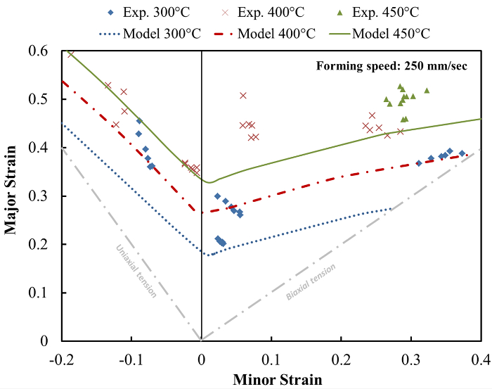
图1: 在不同温度下的实验,并预测成形极限应变的比较。成形极限菌株随着温度升高,在250毫米的恒定速度/秒,或等同地,6.26 -1的应变速率。 请点击此处查看该图的放大版本。
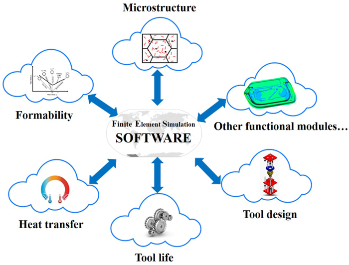
图 2: 一个金属板材成形工艺的基础知识云的有限元模拟原理图。商用有限元模拟软件,是用来运行模拟和导出各个模块所要求的结果。这些模块, 例如 ,成形性,热传导,形成后强度(微观),刀具寿命预测,模具设计等 ,在云中同时独立工作,从而使前沿知识从多个来源成有限元模拟的融合。 请CLICK这里查看该图的放大版本。
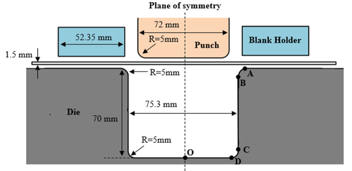
图3: 工件和工具的U形弯曲模拟的几何。该工具, 即冲,压边和模具,使用刚性单元模拟。壳单元被用于对工件(空白)的元件。 请点击此处查看该图的放大版本。
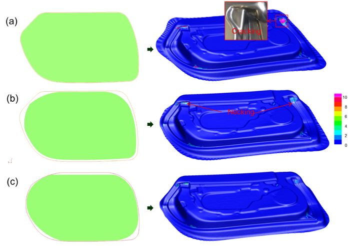
图 4: 门内板(在有限元模拟显示)的烫金坯料形状的演变。剩下: 绿色帧中的数字代表每个优化阶段空白的形状,并以红色的那些帧对应于它的优化前的毛坯形状。右:在每一个优化缩颈的预测结果。 (a)用大故障的初步结果(裂化/缩颈所示红色),(B)减少未与优化的第一级,(c)与不可见的颈缩最终优化毛坯形状后一些缩颈。 请点击此处查看该图的放大版本。

图5:剩余涂层厚度分布(在有限元模拟显示)与压边力:(1)5千牛顿,(B)20千牛,和(c)50千牛,在250一个恒定的冲压速度300形成循环后毫米/秒。 请点击此处查看该图的放大版本。
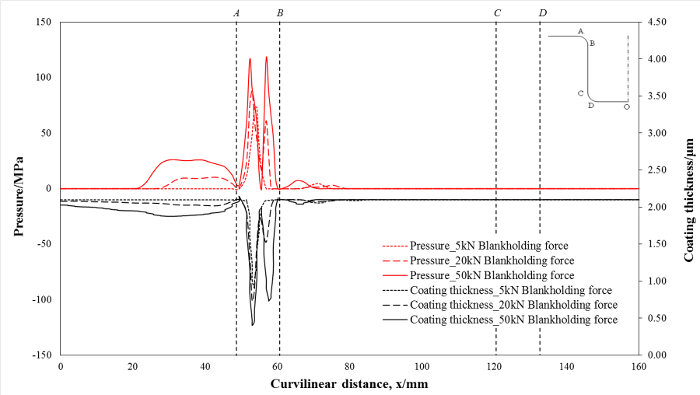
图6:接触压力的预测和剩余涂层厚度与压边力:(1)5千牛,(B)20千牛,以及(c)50千牛,沿着模具的曲线距离在250恒定的烫印速度毫米/秒。 请点击此处查看该图的放大版本。
讨论
该KBC-FE模拟技术实现先进的模拟,以使用专用的模块进行场外。它可以运行于云环境的功能模块,即从不同的特化连接起来的节点,以确保过程仿真尽可能准确地进行。在KBC-FE模拟关键方面可能涉及有限码的独立性,计算的效率和功能模块的准确度。每个高级功能的一个模块中实现将依赖于一个新的模型和/或一个新的实验技术的发展。例如,成形极限模块是基于新的统一的成形极限预测模型11开发的,摩擦刀具寿命预测模块目前已经被互动式摩擦模型20实施开发。该KBC-FE模拟技术也提供了选择性的计算履行选择功能, 也就是说 ,只有元素标准选择用于各个模块进一步的评估。例如,工具寿命预测模块自动选择其中硬涂层倾向于破裂,由排名第1的所有元素的磨损率成形周期的元素,该元素的因而通常小于1%将被选择用于进一步多周期载荷条件下的刀具寿命评估。在本研究中,300形成循环后的工具寿命预测可在5分钟内完成。
通过进行相关试验,并相应地校准,成形极限模型可以适用于形成处理模拟,以从而确定用于成功地产生由这种合金的组分的最佳参数,并且没有缩颈的发生率。成形极限预测模型被开发为,这是独立的有限元软件的被利用云模块,并且可以被应用到任何有限元软件评估过程中的材料的成形性成形,无需复杂的子程序17。通过导入相关数据到模型,计算可以被进行,以确定故障是否发生,在该用户可以指定该组件的区域,从而节省了计算资源。然而,应该指出的是,作为应力 - 应变曲线是输入到通过简单的查表的有限元软件,可能难以在模拟过程中,以充分代表在不同温度和应变率的材料特性。
在刀具寿命预测模块,成型过程中的摩擦行为可以通过导入所需的变形历史数据到验证摩擦模块20,然后再导入为每个元素放回有限元软件的云模块计算出的离散数据点进行预测。这保证了高级摩擦模块可以被所有的FE码被使用,无论其掺入用户子程序能力。此外,国防部ULE可以并行运行,以进一步减少计算时间。交互式摩擦/磨损模型假定没有磨损颗粒的过程中的初始滑动,并作为一个结果,这将是合理的预期摩擦系数0.17 20的恒定初始值。尽管该模型揭示摩擦分布的演变,在成形过程中的摩擦行为是非常复杂的,并且难以从云模块的复合摩擦行为完全融入有限元模拟。
作为未来的技术,KBC-FE模拟将依靠专用基础和强大的互联网有限元模拟软件包开发,这需要一个高利润,但完全不同的商业模式,由软件开发商建立。此外,专用的内部网络需要在合作各方内部建立确保数据安全和工业系统的控制可靠性。
披露声明
The authors have nothing to disclose.
致谢
The financial support from Innovate UK, Ultra-light Car Bodies (UlCab, reference 101568) and Make it lighter, with less (LightBlank, reference 131818) are gratefully acknowledged. The research leading to these results has received funding from the European Union's Seventh Framework Program (FP7/2007-2013) under grant agreement No. 604240, project title 'An industrial system enabling the use of a patented, lab-proven materials processing technology for Low Cost forming of Lightweight structures for transportation industries (LoCoLite)'. Significant support was also received from the AVIC Centre for Structural Design and Manufacture at Imperial College London, which is funded by Aviation Industry Corporation of China (AVIC).
材料
| Name | Company | Catalog Number | Comments |
| AA6082-T6 | AMAG | Material | |
| AA5754-H111 | AMAG | Material | |
| 1,000 kN high-speed press | ESH | Forming press | |
| ARGUS | GOM | Optical forming analysis | |
| PAM-STAMP 2015 | ESI | FE simulation software | |
| Matlab | MathWorks | Numerical calculation software | |
| Gleeble 3800 | DSI | Uniaxial tensile test | |
| High Temperature Tribometer (THT) | Anton Paar | Friction property test | |
| NewViewTM 7100 | ZYGO | Surface profilometer | |
| Magnetron sputtering equipment | Coating deposition | ||
| Microhardness tester | Wolpert Wilson Instruments | ||
| Nano-hardness indenter | MTS |
参考文献
- Miller, W. S., et al. Recent development in aluminium alloys for the automotive industry. Mater. Sci. Eng. A. 280 (1), 37-49 (2000).
- Bolt, P. J., Lamboo, N. A. P. M., Rozier, P. J. C. M. Feasibility of warm drawing of aluminium products. J. Mater. Process. Tech. 115 (1), 118-121 (2001).
- Li, D., Ghosh, A., et al. Effects of temperature and blank holding force on biaxial forming behavior of aluminum sheet alloys. J. Mater. Eng. Perform. 13 (3), 348-360 (2004).
- Toros, S., Ozturk, F., Kacar, I. Review of warm forming of aluminum-magnesium alloys. J. Mater. Process. Tech. 207 (1-3), 1-12 (2008).
- Wang, L., Strangwood, M., Balint, D., Lin, J., Dean, T. A. Formability and failure mechanisms of AA2024 under hot forming conditions. Mater. Sci. Eng. A. 528 (6), 2648-2656 (2011).
- Wang, L., et al. . TTP2013 Tools and Technologies for Processing Ultra High Strength Materials. , (2013).
- El Fakir, O., et al. Numerical study of the solution heat treatment, forming, and in-die quenching (HFQ) process on AA5754. Int. J. Mach. Tool. Manu. 87, 39-48 (2014).
- Raugei, M., El Fakir, O., Wang, L., Lin, J., Morrey, D. Life cycle assessment of the potential environmental benefits of a novel hot forming process in automotive manufacturing. J. Clean. Prod. 83, 80-86 (2014).
- Liu, J., Gao, H., Fakir, O. E., Wang, L., Lin, J. HFQ forming of AA6082 tailor welded blanks. MATEC Web of Conferences. 21 (05006), (2015).
- Karbasian, H., Tekkaya, A. E. A review on hot stamping. J. Mater. Process. Tech. 210 (15), 2103-2118 (2010).
- El Fakir, O., Wang, L., Balint, D., Dear, J. P., Lin, J. Predicting Effect of Temperature Strain Rate and Strain Path Changes on Forming Limit of Lightweight Sheet Metal Alloys. Procedia Eng. 81, 736-741 (2014).
- Shi, Z., et al. . the 3rd International Conference on New Forming Technology. , 100-104 (2012).
- Mohamed, M. S., Foster, A. D., Lin, J., Balint, D. S., Dean, T. A. Investigation of deformation and failure features in hot stamping of AA6082: Experimentation and modelling. Int. J. Mach. Tool. Manu. 53 (1), 27-38 (2012).
- Hosford, W. F. Comments on anisotropic yield criteria. Int. J. Mech. Sci. 27 (7), 423-427 (1985).
- Marciniak, Z., Kuczyński, K. Limit strains in the processes of stretch-forming sheet metal. Int. J. Mech. Sci. 9 (9), 609-620 (1967).
- Ma, G., Wang, L., Gao, H., Zhang, J., Reddyhoff, T. The friction coefficient evolution of a TiN coated contact during sliding wear. Appl. Surf. Sci. 345, 109-115 (2015).
- Põdra, P., Andersson, S. Simulating sliding wear with finite element method. Tribol. Int. 32 (2), 71-81 (1999).
- Archard, J. F. Contact and Rubbing of Flat Surfaces. J. Appl. Phys. 24 (8), 981-988 (1953).
- Liu, X., et al. Determination of the interfacial heat transfer coefficient in the hot stamping of AA7075. MATEC Web of Conferences. 21 (05003), (2015).
转载和许可
请求许可使用此 JoVE 文章的文本或图形
请求许可探索更多文章
This article has been published
Video Coming Soon
版权所属 © 2025 MyJoVE 公司版权所有,本公司不涉及任何医疗业务和医疗服务。