Method Article
シートメタル成形プロセスの知識ベースのクラウドFEシミュレーション
要約
The following paper presents a novel FE simulation technique (KBC-FE), which reduces computational cost by performing simulations on a cloud computing environment, through the application of individual modules. Moreover, it establishes a seamless collaborative network between world leading scientists, enabling the integration of cutting edge knowledge modules into FE simulations.
要約
The use of Finite Element (FE) simulation software to adequately predict the outcome of sheet metal forming processes is crucial to enhancing the efficiency and lowering the development time of such processes, whilst reducing costs involved in trial-and-error prototyping. Recent focus on the substitution of steel components with aluminum alloy alternatives in the automotive and aerospace sectors has increased the need to simulate the forming behavior of such alloys for ever more complex component geometries. However these alloys, and in particular their high strength variants, exhibit limited formability at room temperature, and high temperature manufacturing technologies have been developed to form them. Consequently, advanced constitutive models are required to reflect the associated temperature and strain rate effects. Simulating such behavior is computationally very expensive using conventional FE simulation techniques.
This paper presents a novel Knowledge Based Cloud FE (KBC-FE) simulation technique that combines advanced material and friction models with conventional FE simulations in an efficient manner thus enhancing the capability of commercial simulation software packages. The application of these methods is demonstrated through two example case studies, namely: the prediction of a material's forming limit under hot stamping conditions, and the tool life prediction under multi-cycle loading conditions.
概要
Finite Element (FE) simulations have become a powerful tool for optimizing process parameters in the metal forming industry. The reliability of FE simulation results is dependent on the accuracy of the material definition, input in the form of flow stress data or constitutive equations, and the assignment of the boundary conditions, such as the friction coefficient and the heat transfer coefficient. In the past few years, advanced FE simulations have been developed via the implementation of user-defined subroutines, which have significantly broadened the capability of FE software.
The use of such advanced FE simulations in the design of forming processes for structural components has been investigated by both the aviation and automotive industries, with the intention of producing lightweight structures that reduces operating costs and CO2 emissions. Particular focus has been placed on the replacement of steel components with lower density materials, such as aluminum alloys and magnesium alloys. However, these alloys, especially the stronger variants, offer limited formability at room temperature and thus complex-shaped components cannot be manufactured using the conventional cold stamping process. Therefore, advanced high temperature forming technologies, such as warm aluminum forming 1-4, hot stamping of aluminum alloys 5-9 and hot stamping of high strength steels 10, have been developed over the past decades to enable complex-shaped components to be formed. In general, high temperature forming processes involve significant temperature variations, strain rate and loading path changes 11, which would, for instance, cause inevitable viscoplastic and loading history dependent responses from the work piece materials. These are intrinsic features of high temperature forming processes and may be difficult to represent using conventional FE simulation techniques. Another desirable feature would be the ability to predict the tool life over multiple forming cycles in such processes, since they require low friction characteristics achieved through coatings that degrade with each forming operation. To represent all these features via the implementation of user-defined subroutines would be computationally very expensive. Moreover, the development and implementation of multiple subroutines would require excessive multi-disciplinary knowledge from an engineer conducting the simulations.
In the present work, a novel Knowledge Based Cloud FE (KBC-FE) simulation technique is proposed, based on the application of modules on a cloud computing environment, that enables an efficient and effective method of modeling advanced forming features in conjunction with conventional FE simulations. In this technique, data from the FE software is processed at each cloud module, and then imported back into the FE software in the relevant consistent format, for further processing and analysis. The development of these modules and their implementation in the KBC-FE is detailed.
プロトコル
高温成形限界予測モデルの1開発
- レーザは、選択された幾何学的形状12にアルミニウム合金AA6082シート(厚さ1.5mm)の成形性試験用の試験片を切断します。
- 電解法13を用いて、試験片の表面に1mmの規則的な間隔0.75ミリメートルの直径の円形の点から成るグリッドパターンを、エッチングします。
- 手動でエッチングされていない側の潤滑剤としてグラファイトグリースを塗布してください。
- 油圧プレス12高率でドーム試験リグを組み立てます。 250 kNの油圧式万能試験機を使用してください。
- 試験温度にドーム試験装置を加熱し、一定の移動速度でパンチを設定します。その後、テストを開始します。
注:試験温度はそれぞれ、300、400、450°Cです。試験速度は75、250、および400ミリメートル/秒あります。 - ネッキングの最初の発生時にテストを停止します。
注:プレスstrokをE( すなわち、最終的な試料の高さ)は、ネッキングがちょうど形成された試料で観察されるように設定されています。 - 高さゲージを使用して、最終的な試料高さを測定し、分析装置を構成する光学3Dを使用して株および最大歪み速度(時間に対する歪みの変化率)を算出します。形成された試料の各点で株を計算するために、グリッド間隔の変化を分析します。
- 光学3次元解析システムを構成することを確認し、カメラ形成検体、キャリブレーションスケールバー14を含みます。
注意:試料はターンテーブルの中央に配置し、スケールバーで囲まれ、そしてそれらの相対位置は、分析の期間中一定に保たれているされています。 - 試料に一定の標高( 例えば、50センチ)と角度( 例えば、30、50、または70°)にカメラを設定し、15°刻みで、ターンテーブルの完全な回転(360°)の上に写真を撮ります。
注:presaの複数形でNT作業は、画像の三組は、全試料15上に歪みをマッピングするために複数のカメラ上昇および角度から取得しました。 - 解析ソフトウェアを構成する光3Dにイメージをロードし、歪みを計算するために進んでください。グリッドを構築する「コンピュート3次元点とグリッド」機能をクリックし、続いて格子点を検出」の計算の楕円とバンドル」機能、をクリックして行います。
注:株を計算し、評価モードでそれを可視化します。 - 出力の歪み分布はISO 12004 16に基づいて、各検体の限界株を決定し、別の成形速度と成形温度のための成形限界線図をプロットします。
- 0.1〜10秒から300〜500℃、歪み速度に異なる温度でAA6082のための材料モデルを校正-1。
注:材料モデルとAA6082のためにその定数参照17に詳述されています。 - 成形限界予測モデルを定式化するために、積分アルゴリズムにステップ1.12でハスフォード異方性降伏関数18、マーシニャク-クチンスキー(MK)理論19と材料モデルを実装し、統一。
注:モデルは、基準11に記載されています。 - ステップ1.11で得られた実験結果を用いて、ステップ1.13のために開発したモデルを校正し、確認します。
- ステップ1.14から検証モデル11を介して形成限界を予測します。
注: 図1は、6.26秒の歪速度、250ミリメートル/秒の成膜速度で、異なる温度で得られたモデル予測を示している、または同等-1。
インタラクティブ摩擦/摩耗モデルの2.開発
- コーティングされた(ディスク)試料についてボールオンディスクテストを実行します
- 軸受鋼に窒化チタン(TiN)コーティングを調製GCr15ディスク参照20で与えられた堆積パラメータで、陰極アークとミッド周波数マグネトロンスパッタ法を用いました。
- 走査型電子顕微鏡(SEM)を使用して、コーティングされた試料の表面/断面形状を得ます。ベースコーティング材料のトポグラフィー(明るさと契約)を比較することによって、SEM像を介して錫被覆厚さを測定します。
注意:実験手順を参照20で見つけることができます。 - 試料の表面粗さを得るために、インターフェロメトリック表面プロfilometer白色光を使用してください。レンズの下にサンプルを置き、明確な表面構造を得るために顕微鏡を調整します。サンプルを照明し、(画面から監視することができます)明確な干渉ストリップを観察するためにx軸とy軸の角度を調整します。ソフトウェアで総深さを設定し、測定を開始します。自動試料表面を走査し、表面粗さを計算します。
- O付着強度を評価マイクロスクラッチ試験機を使用してサンプルF。増加する負荷(最大50 N)とTiNコーティングの傷の距離(最大5ミリメートル)を適用します。コーティングの故障の原因となる重要な負荷を決定し、マイクロスクラッチ曲線20を得ます。
- 硬度の圧子を用いて試料の硬さを評価します。 15秒間のサンプルに20 Nの静荷重を適用します。圧子によって作られた印象の対角を測定し、その後、テスタから硬度値を得ます。
- 周囲環境(温度25℃、湿度30%)で摩擦計にボールオンディスク試験を行います。コーティングされたディスクに対する対応として、直径6mm WC-6%のボール(マイクロ硬度1780 HV、摩耗強度1380 N / cmで、弾性率71 GPaで)を使用します。 / sの5ミリメートルに相対滑り速度を調整します。摩擦計を用いたモータとレコード摩擦値を開始し200 Nの垂直荷重を適用します。 Oを使用して摩耗痕跡を分析するために、それぞれ、180秒、350秒、400秒、450秒で試験を中断ptical顕微鏡20。
- 試験後の白色光干渉表面プロフィルを使用して、摩耗表面のトポグラフィーを測定します。
- 別の正常な負荷(300 N、400 N)とテスト(ステップ2.1.6)を繰り返します。
- 摩擦係数が急激に増加することを特徴と硬質皮膜の破壊までの摩擦係数の変化を決定します
- ステップ2.1.6で摩擦値を記録した後、時間に対する摩擦係数の変化をプロットします。
注:摩擦係数の進化は、基準20に提示されています。 - 摩耗挙動および関連するメカニズムの面で摩擦係数の変化を評価します。
注:(I)低摩擦段階、(ii)の耕起摩擦段階、および(iii)コーティング破壊ステージ20,21:摩擦の進化は、3つの異なる段階に特徴づけられます。 - 磨耗の評価その後、手動でテストを中断することにより、180秒でtates、および光学顕微鏡を用いて摩耗トラックを分析します。
注:このステップはステップ2.2.2で説明したように、低摩擦段の摩耗粉を調査することです。 - それぞれ350秒、400秒、450秒、時を繰り返し、ステップ2.2.3。
- ステップ2.1.6で摩擦値を記録した後、時間に対する摩擦係数の変化をプロットします。
- インタラクティブな摩擦モデルを開発
- ハードウェア粒子の耕摩擦で初期摩擦μαを組み合わせて、全体的な摩擦係数μを特徴付けるμPC(式に示すように、(1))20。
(1)
- 耕起摩擦μ のPCコーティング破壊誘発性急激な増加をモデル化するために、瞬時のコーティング厚さ(H)と、ボールと、基板(μPS)との間で耕し摩擦結合(式(2))。
注意:残りのコーティング厚さがゼロである場合この場合、μPcは Psが μ(ハードコートの完全な分解を示す)に等しいです。
(2)
ここで、λ1およびλ2は、摩耗プロセスの物理的な意味を表現するために導入されたモデルパラメータです。 λ1は、大きな封入磨耗粒子の影響を説明し、λ2は、摩擦係数の勾配によって特徴付けられる耕作摩擦効果の強度を表します。 - 残りのコーティング厚さの変化を取得し、変化する接触条件下での累積摩耗をモデル化するために時間ベースの積分アルゴリズムを使用します。式により各計算ループにおけるコーティングの厚さを更新します。 (3)。
(3)
H 0は、最初のコーティングの厚さであり、コーティングの時間依存性の摩耗率です。 - Archard服法則22(式(4))を変更し、現在のモデルでそれを実装します。
(4)
Kは、摩耗係数であり、Pは、接触圧は、vは滑り速度であり、H cは 、コーティングと基板の組み合わせ硬度です。 - 合わせた硬さを計算するKorsunskyのモデルを使用する(式(5))。
(5)
H sは 、基板の硬さであり、αは、コーティングと基板とβとの間の硬度の比は厚みの影響係数です。 - 電源リットルによって負荷依存のパラメータλ1およびKを表しますAW方程式。
(6)
(7)
κのλ1、κK、Ν のλ1とΝKは摩擦20の進化に関連した材料定数です。 - モデルパラメータを決定するために、著者らのグループで開発積分アルゴリズムを用いた実験結果をインタラクティブ摩擦モデルを適合。
- ハードウェア粒子の耕摩擦で初期摩擦μαを組み合わせて、全体的な摩擦係数μを特徴付けるμPC(式に示すように、(1))20。
3. KBC-FEシミュレーションケーススタディ
- KBC-FEシミュレーションケーススタディ1:ホットスタンプ条件下での成形限界の予測
- FEシミュレーションソフトウェアの新しいシミュレーションプロジェクトを作成し、名前を付けます。 「 スタンプ熱間成形 」などのプロセスと「PAM-AutoStamp」などのソルバーのタイプを選択しますプロジェクトを保存します。
- FEシミュレーションソフトウェアグラフィックインターフェイスにドアインナ「IGS」ジオメトリファイル」をインポートツールCAD」をクリックし、「 インポート&transfe R 'でドア内側のダイをインポートします。ツールの噛み合いのための「 ホット形成の戦略を選択します。 「 ダイ 」としてインポートされたオブジェクトに名前を付けます。
- それぞれを繰り返し、ステップ3.1.2とパンチとBlankholderの「 輸入 」のオブジェクト、。
- 「 セットアップ 」タブの「 ブランク 」をクリックします。クリックして「 ブランクエディタ 」で「 空白の追加 」、および「 ブランク 」として「 新しいオブジェクト」を設定します。そして、「 サーフェスブランク 」とタイプを選択します。
- 定義タイプのための「 アウトライン」を選択し、ブランク形状bをインポートします「CADファイルからインポート 」上のyクリックします。 「 課せられたレベル 」と「 洗練」を定義し、「 メッシュオプション 」の下でレベル1を選択します。 「 自動メッシング 'と4ミリメートルに設定し「 メッシュサイズ」をオフにします。
- 「 ブランクエディタ 」で材料特性を定義します。 「 素材 」タブで「 材料をロード 」をクリックします。 「AA6082」を選択します(単位:ミリ・キログラム・秒・C)の材料特性などの材料。 'X = 1'から' 圧延方向」を設定します。 2ミリメートルの「 ブランクの厚さ 」、および490℃までの空白」 の初期温度」を設定します。
注:材料特性と材料モデルは、参照17に記載されています。 - プロセス 」をクリックします セットアップ 」タブを選択し、「+」アイコンを「下」は新しいマクロをロードします。 'スタンプの Hotforming」を参照し、「HF_Validation_DoubleAction_GPa.ksa」を選択します。 「 カスタマイズ 」ダイアログで、ブランク、ダイ、パンチ、およびBlankholderを活性化させます。 「 ステージ 」タブで、重力、手に持つ、スタンプ、および焼入れを活性化させます。
- 実際の実験のセットアップ(空白の保持力= 50 kNの、スピード= 250ミリメートル/秒を形成し、摩擦係数= 0.1に対応する「 セットアップ 」タブの下の属性をオブジェクト '、熱伝達のように23係数ですべてのパラメータを設定しますギャップとの接触圧力の関数)。
- クリックして、シミュレーションのセットアップをチェックして、上記の設定に誤りがないことを確実にするアイコンを「 チェック 」。
- SIを開始するために「 計算 」アイコンをクリックしますmulation。
注:このソフトウェアは、ホストコンピュータでシミュレーション中に11の状態を記録します。 - シミュレーションが完了した後、FEシミュレーションソフトウェアのグラフィカルインタフェースのシミュレーション結果を観察し、輪郭値をエクスポートアクションの「 スクリプト 」、 すなわち、主要な株(膜)、マイナー株(膜)、および温度を記録するために進みます指定されたシミュレーション状態のためのすべての空白の要素、の。手動で' レコード 'と輸出輪郭値をクリックします。録音を停止するには「 停止」をクリックしてください。全11のシミュレーション状態に対して同じアクションを繰り返すようにスクリプトを保存します。
- スクリプトをロードするために「 再生 」アイコンをクリックして、輪郭値をエクスポートするには、「 すべて行います 」をクリックします。
注:各個々の輪郭/状態の場合、ソフトウェアは自動的に「major_strain_staten下'ASCII」ファイル内の値をエクスポートアンバー'、'それぞれminor_strain_statenumber '、および' temperature_statenumber '、。 - クラウドコンピュータにエクスポートされたすべてのファイルを保存します。クラウドコンピュータ内のすべてのエクスポートされたファイルと一緒に「 ネッキング予測モデル 」( すなわち、雲のモジュールコード)を実行します。
- クラウドコンピュータに制限予測モデルを形成するの使用によりネッキングの発生を予測します。
注:このモデル11は、ユーザーが個々の要素またはブランクのすべての要素に予測モデルを実行するオプションを提供します。 - 手動で入力シミュレーションの詳細/ ' ネッキング予測モデル 」のパラメータ。入力シミュレーションにおける状態数(状態11)、スタンピングプロセス(157ミリメートル)の合計ストローク、スタンピング速度(250ミリメートル/秒)、関心のひずみ範囲(要素の選択基準、 例えば、株> 0.2)とすべての要素。
注:ストラ範囲内でネッキングは例えば 、要素の基準を設定することで、場所をとることができるための要素を制限し、最終的に主要なひずみ0.2以上でのみの要素は、モジュールのさらなる評価のために選択されています。 - クラウド・コンピューターにモジュールの計算を完了した後、自動的にフォーマット'ASCII'ファイルに(予測結果ネッキング)すべてのデータを保存します。
- FEシミュレーション結果の最終状態をロードします。 「 輪郭 」タブで、次に「 インポート 」と「 スカラー値 」をクリックします。上記の工程から得られた「ASCII」ファイルを選択します。 FEシミュレーションソフトウェアでネッキング予測結果を表示します。
- KBC-FEシミュレーションケーススタディ2:マルチサイクル負荷条件の下で工具寿命予測
- FEシミュレーションソフトウェアの新しいシミュレーションプロジェクトを作成し、名前を付けます。 PROCを選択プロジェクトを保存するときに「PAM-AutoStamp」として「 標準スタンピング 」とソルバータイプとしてエス。
- FEシミュレーションソフトウェアグラフィックインターフェースに「 インポートツールCAD 'とし、' インポート&転送 「U字型」IGS」ジオメトリファイルをクリックすることで、ダイのジオメトリをインポートします。ツールの噛み合いのための「 検証 」の戦略を選択します。 「 ダイ 」としてインポートされたオブジェクトに名前を付けます。
- 繰り返しステップ3.2.2はそれぞれ、パンチとBlankholderのオブジェクトをインポートします。
- 「 セットアップ 」タブの「 ブランク 」をクリックします。 「 ブランクエディタ 」で「 空白の追加 」「 ブランク 」として「 新OBJEC T ' を設定し、「 ブランク表面 」とタイプを選択します。 「 フォーポイを選択してください定義タイプのためのNTS」とは、120×80ミリメートル2に空白サイズを設定します。 「 メッシュオプション 」の下にレベル1:「 課せられたレベル 」としての「 洗練」を定義します。 「 自動メッシュ生成」をオフにして、1.5ミリメートルに「 メッシュサイズ」を設定します。
- 「 ブランクエディタ 」で材料特性を定義します。 「 素材 」タブの下の「 ロード材料」をクリックします。 「AA5754-H111」を選択(単位:ミリメートル・キログラム・秒・C)の材料特性などの材料。 'X = 1'から' 圧延方向」を設定します。 1.5ミリメートルの「 ブランクの厚さ」を設定します。
- 「 セットアップ ]タブの[ プロセス ]をクリックし、[新しいマクロをロードするために「+」アイコンを選択します。を参照'スタンプフィージビリティ 'と'SingleActioin_GPa.ksa」を選択します。 「 カスタマイズ 」ダイアログで、ブランク、ダイ、パンチ、およびBlankholderを活性化させます。 「 ステージ 」の下では、重力、手に持つ、およびスタンピングを活性化させます。
- 実際の実験のセットアップに対応してシミュレーションですべての「 パラメータ」を設定します(空白の保持力= 5、20、50 kNの、それぞれ、成形速度= 250ミリメートル/秒、摩擦係数= 0.17)。
- シミュレーションのセットアップ」を確認してください 」と、上記の設定に誤りがないことを確実。
- 「 計算 」アイコンをクリックして、ホストコンピュータ11-状態U字曲げシミュレーションのための「 計算」を開始します。
- シミュレーションの完了後、エクスポートは自動的にワークピースのためのデータと「 接触圧力のデータを座標 ''と(ステップ3.1.11および3.1.12あたりなど) 'ASCII」ファイルなどのツール(パンチ死ぬとブランクホルダ)。
- クラウドコンピュータにエクスポートされたすべてのファイルを保存します。クラウドコンピュータ内のすべてのエクスポートされたファイルと一緒に「 工具寿命予測モジュール」を実行します。
- 手動入力は、「 工具寿命予測モジュール 」のパラメータを形成します。入力、次のパラメータ:状態数(状態11)、全ストローク(70ミリメートル)、速度(250ミリメートル/秒)と、初期摩擦係数(0.17)を刻印。
- ツールを選択(、パンチ死ぬ、またはブランクホルダ)、その後、単一の要素またはすべての要素の計算を開始します。
- クラウドコンピュータ内のモジュール計算の終了後、自動的にフォーマット'ASCII'ファイルに(瞬時残りのコーティングの厚さと摩擦係数を含む)すべてのデータを保存します。
- 負荷は、残りの被覆厚さとfrictiを表示しますFEシミュレーションソフトウェアで関連する要素の係数に(ステップ3.1.17あたりなど)。
結果
ネッキング予測のためのKBC-FEシミュレーション
ホットスタンピングプロセスでは、形状最適化されたブランクの使用は、材料費を節約するだけでなく、このような、ネッキング割れ、およびしわなどの欠陥の存在を減らすのに役立つだけでなく。初期ブランク形状は成形時に大幅に材料の流れに影響を及ぼし、ひいてはブランク形状の賢明なデザインは、最終製品のホットスタンピングプロセスと品質の成功に不可欠です。最適なブランク形状を決定するために試行錯誤実験の努力を低減するために、KBC-FEシミュレーションネッキングと領域を最小化するための非常に効率的かつ効果的な方法であることが証明されました。予測ネッキング並列クラウドモジュール計算は4時間以内に完了している間、この技術を用いて、各シミュレーションは、約2時間かかります。
図4は、自動車のドア内部成分の例として、ホットスタンプに使用されるブランク形状の進化を示しています。従来の冷間プレス法から採用した初期ブランク形状は、第一のKBC-FEシミュレーションに使用しました。 図4の実験結果は、(a)は、大規模な障害が(亀裂又はネッキング)領域がホットスタンピング後に表示されていることを示しています。ブランク形状最適化の反復の後、最初のブランク形状を使用することに比べて、ほぼ完全に成功したパネルは、はるかに少ないネッキングが形成されていること(b)は図4に見ることができます。右上のパネルの左コーナーでポケットにネッキングの兆候がまだ存在することがわかります。 図4(c)の中で更なる最適化した後、最適化されたブランクの形状は、最終的には、パネル上の目に見えるネッキングが得られました。 KBC-FEシミュレーションによって決定される最適化されたブランクの形状はホットスタンピングを通じて実験的に検証しました試験は、生産システムのメーカーが提供する完全に自動化生産ラインで実施しました。
工具寿命予測のためのKBC-FEシミュレーション
金属成形プロセスの従来のFEシミュレーションは、単一サイクルのために行われています。ただし、本番環境では、複数の成形サイクルは、形成サイクル数の増加は、形成された構成要素間の増加変化をもたらすことが見出されている所与のツールで実行されます。マルチサイクルツールローディング中、この変形は、表面形状の変化の結果です。例えば、機能性コーティングとツールを形成するマルチサイクル負荷は、磨耗によるコーティングの厚さの減少につながります。また、塗膜の絶縁破壊もKBC-FE技術が可能にするなど 、スピードを形成する、そのような負荷/圧力などのパラメータを形成することによって影響を受けます高度な機能性コーティングを有する成形工具のインサービス寿命予測のために不可欠であるマルチサイクル負荷条件の下でプロセスを構成する板金のシミュレーション。
工具寿命のブランク保持力、5、20、および50 kNのブランク保持力値の影響を調べる250 mm /秒の一定の成膜速度を調べました。 図5は、300サイクルを形成した後に別の空白の保持力を持つ残りの工具コーティング厚分布を示しています。これは明らかに、残りの被覆厚さが空白の保持力の増加に伴って減少することを示しています。
図6は、300サイクルを形成した後、金型の曲線の距離に沿って、それぞれ、圧力および5の空白の保持力で、残りの膜厚分布を示している20、および50 kNの。地域以来ABは、ダイ耳鼻咽喉科を表し、U字曲げ加工時のランスの領域は、圧力と、この領域の相対摩耗距離は、ダイの他の領域よりもはるかに高かったです。その結果、コーティングの摩耗は主にこの地域で発生しました。 20 kNのでコーティング厚さの減少の2ピーク値と圧力の下に2つのピークに対応50 kNのがあります。一方、残りのコーティングの厚さは、空白の保持力の増加に伴って減少します。最初のコーティングの厚さは2.1ミクロンであった場合に5、20、および50 kNののしわ押さえ力と最低の残りのコーティング厚さは、それぞれ、0.905、0.570、及び0.403ミクロンでした。
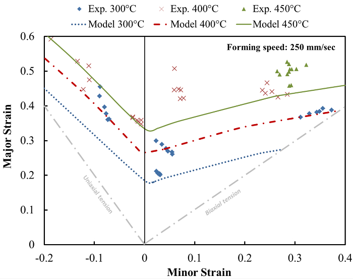
図1: 実験と異なる温度で制限株を形成する予測との比較。成形限界株250 [mm]の一定速度で、温度が上昇するにつれて増加します/秒、または同等に、6.26秒-1の歪み速度。 この図の拡大版をご覧になるにはこちらをクリックしてください。
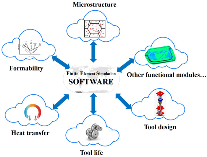
図2: シートメタル成形プロセスの知識ベースのクラウドFEシミュレーションのための模式図。商業FEシミュレーションソフトウェアは、シミュレーションを実行し、個々のモジュールに必要な結果をエクスポートするために使用されます。モジュールなど 、 例えば 、成形性、熱移動、成形後強度(微細構造)、工具寿命予測、ツール設計は、従ってFEシミュレーションに複数のソースからエッジ知識を切断の統合を可能にする、クラウドで同時にかつ独立して動作します。 CLくださいこの図の拡大版を表示するには、こちらICK。
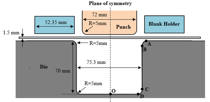
図3:U 字曲げシミュレーションのためのワークやツールのジオメトリ。ツール、 すなわち、ブランクホルダーをパンチ及びダイは、剛性要素を用いてモデル化されています。シェル要素は、ワークピース(ブランク)の要素のために使用されます。 この図の拡大版をご覧になるにはこちらをクリックしてください。
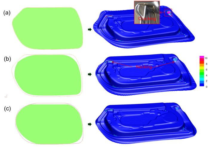
図4:(FE シミュレーションに表示されます)ドアインナーパネルのホットスタンピングのためのブランク形状の進化。左: 緑の枠内の数字は空白の各最適化段階での形状、および赤でものを表しますフレームは、その最適化前のブランク形状に対応します。右:各最適化段階での予測結果をネッキング。 (a)は大失敗いくつかは、最適化の最初の段階の後にネッキングと(クラッキング/赤色で示しネッキング)、(b)の削減、障害、目に見えるネッキングと(c)の最終的な最適化されたブランク形状の最初の結果を。 この図の拡大版をご覧になるにはこちらをクリックしてください。

図5のブランク保持力で残りの膜厚分布(FEシミュレーションで表示):(A)5 kNの、(B)20 kNの、および(c)50 kNの、300は250の一定のプレス速度でサイクルを形成した後ミリ/秒。 お願いしますこの図の拡大版をご覧になるにはこちらをクリックしてください。
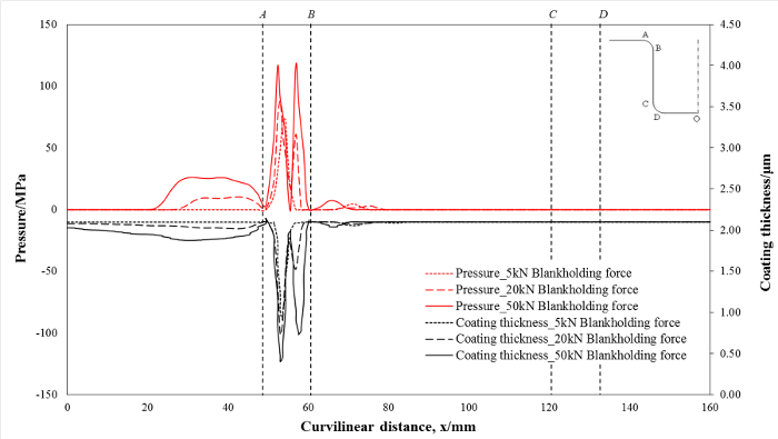
図6:接触圧力の予測との空白の保持力で、残りのコーティング厚さ:(a)は5 kNの、(b)は20 kNの、および(c)50 kNの、250の一定のスタンピング速度で金型の曲線の距離に沿ってミリ/秒。 この図の拡大版をご覧になるにはこちらをクリックしてください。
ディスカッション
KBC-FEシミュレーション技術は、専用のモジュールを使用してサイトをオフに実施する高度なシミュレーションを可能にします。これは、そのプロセスのシミュレーションは、可能な限り正確に行われていることを確認するために、異なる専門分野からノードをリンクアップ、クラウド環境上の機能モジュールを、実行することができます。 KBC-FEシミュレーションにおける重要な側面は、機能モジュールのFEコードの独立性、計算効率、精度を含むことができます。モジュール内の各高度な機能の実現は、新しいモデルおよび/または新たな実験技術の開発に依存しているだろう。例えば、成形限界モジュールは、新しい統一成形限界予測モデル11、及び摩擦工具寿命予測モジュールに基づいて開発され、現在のインタラクティブ摩擦モデル20の実装によって開発されました。 KBC-FEシミュレーション技術はまた、 すなわち 、選択を満たす要素だけを選択的に計算する機能を提供しています基準は、個々のモジュールのさらなる評価のために選択されています。例えば、工具寿命予測モジュールが自動的にハードコーティングが破壊する傾向があるために要素を選択し、サイクルを形成する第1のすべての要素の摩耗率をランク付けすることにより、このように通常の要素の1%未満をさらにために選択されますマルチサイクル負荷条件の下で工具寿命の評価。本研究では、300サイクル後の成形工具寿命予測は、5分以内に完了することができます。
関連する試験を実施し、それに応じて較正することによって、成形限界モデルは、結果的に成功し、ネッキングのない発生率を有するような合金から部品を製造するための最適なパラメータを決定するプロセスのシミュレーションを構成に適用することができます。成形限界予測モデルが利用されているFEソフトウェアの独立したクラウド・モジュールとして開発され、中の材料の成形性を評価するために、任意のFEソフトウェアに適用することができます複雑なサブルーチン17なしで形成します。モデルに関連するデータをインポートすることで、計算は、ユーザが、計算資源の節約、指定することができる成分の領域に、障害が発生するかどうかを決定するために行うことができました。しかし、応力 - ひずみ曲線は、単純なルックアップテーブルを介してFEソフトウェアに入力されるように、完全にシミュレーション中に種々の温度及び歪み速度での材料特性を表現することが困難であり得ることに留意すべきです。
工具寿命予測モジュールでは、成形時の摩擦挙動を検証摩擦部20に必要な変形履歴データをインポートし、そして再びFEソフトウェアに各要素のクラウド・モジュールによって計算離散データ点をインポートすることによって予測することができます。これは高度な摩擦・モジュールは、ユーザサブルーチンを取り込む能力に関係なく、すべてのFEコードによって使用され得ることを保証します。また、モッズULEはさらに、計算時間を短縮するために並行して実行することができます。インタラクティブな摩擦/摩耗モデルは、摺動初期の間に摩耗粒子が存在しないことを想定し、その結果、摩擦係数0.17 20の一定の初期値を予想するのが妥当であろう。このモデルは、摩擦分布の変化を明らかにしているが、成形工程の間の摩擦挙動は非常に複雑であり、完全にFEシミュレーションにクラウド・モジュールから複合摩擦挙動を統合することは困難です。
将来の技術として、KBC-FEシミュレーションは、ソフトウェア開発者によって確立されるように収益性の高い、しかし全く異なるビジネスモデルを必要とする専用の堅牢なインターネットベースのFEシミュレーションソフトウェアパッケージの開発、に依存しています。また、専用の内部ネットワークは、データのセキュリティと産業システムの制御の信頼性を確保するために共同の当事者の中構築する必要があります。
開示事項
The authors have nothing to disclose.
謝辞
The financial support from Innovate UK, Ultra-light Car Bodies (UlCab, reference 101568) and Make it lighter, with less (LightBlank, reference 131818) are gratefully acknowledged. The research leading to these results has received funding from the European Union's Seventh Framework Program (FP7/2007-2013) under grant agreement No. 604240, project title 'An industrial system enabling the use of a patented, lab-proven materials processing technology for Low Cost forming of Lightweight structures for transportation industries (LoCoLite)'. Significant support was also received from the AVIC Centre for Structural Design and Manufacture at Imperial College London, which is funded by Aviation Industry Corporation of China (AVIC).
資料
| Name | Company | Catalog Number | Comments |
| AA6082-T6 | AMAG | Material | |
| AA5754-H111 | AMAG | Material | |
| 1,000 kN high-speed press | ESH | Forming press | |
| ARGUS | GOM | Optical forming analysis | |
| PAM-STAMP 2015 | ESI | FE simulation software | |
| Matlab | MathWorks | Numerical calculation software | |
| Gleeble 3800 | DSI | Uniaxial tensile test | |
| High Temperature Tribometer (THT) | Anton Paar | Friction property test | |
| NewViewTM 7100 | ZYGO | Surface profilometer | |
| Magnetron sputtering equipment | Coating deposition | ||
| Microhardness tester | Wolpert Wilson Instruments | ||
| Nano-hardness indenter | MTS |
参考文献
- Miller, W. S., et al. Recent development in aluminium alloys for the automotive industry. Mater. Sci. Eng. A. 280 (1), 37-49 (2000).
- Bolt, P. J., Lamboo, N. A. P. M., Rozier, P. J. C. M. Feasibility of warm drawing of aluminium products. J. Mater. Process. Tech. 115 (1), 118-121 (2001).
- Li, D., Ghosh, A., et al. Effects of temperature and blank holding force on biaxial forming behavior of aluminum sheet alloys. J. Mater. Eng. Perform. 13 (3), 348-360 (2004).
- Toros, S., Ozturk, F., Kacar, I. Review of warm forming of aluminum-magnesium alloys. J. Mater. Process. Tech. 207 (1-3), 1-12 (2008).
- Wang, L., Strangwood, M., Balint, D., Lin, J., Dean, T. A. Formability and failure mechanisms of AA2024 under hot forming conditions. Mater. Sci. Eng. A. 528 (6), 2648-2656 (2011).
- Wang, L., et al. . TTP2013 Tools and Technologies for Processing Ultra High Strength Materials. , (2013).
- El Fakir, O., et al. Numerical study of the solution heat treatment, forming, and in-die quenching (HFQ) process on AA5754. Int. J. Mach. Tool. Manu. 87, 39-48 (2014).
- Raugei, M., El Fakir, O., Wang, L., Lin, J., Morrey, D. Life cycle assessment of the potential environmental benefits of a novel hot forming process in automotive manufacturing. J. Clean. Prod. 83, 80-86 (2014).
- Liu, J., Gao, H., Fakir, O. E., Wang, L., Lin, J. HFQ forming of AA6082 tailor welded blanks. MATEC Web of Conferences. 21 (05006), (2015).
- Karbasian, H., Tekkaya, A. E. A review on hot stamping. J. Mater. Process. Tech. 210 (15), 2103-2118 (2010).
- El Fakir, O., Wang, L., Balint, D., Dear, J. P., Lin, J. Predicting Effect of Temperature Strain Rate and Strain Path Changes on Forming Limit of Lightweight Sheet Metal Alloys. Procedia Eng. 81, 736-741 (2014).
- Shi, Z., et al. . the 3rd International Conference on New Forming Technology. , 100-104 (2012).
- Mohamed, M. S., Foster, A. D., Lin, J., Balint, D. S., Dean, T. A. Investigation of deformation and failure features in hot stamping of AA6082: Experimentation and modelling. Int. J. Mach. Tool. Manu. 53 (1), 27-38 (2012).
- Hosford, W. F. Comments on anisotropic yield criteria. Int. J. Mech. Sci. 27 (7), 423-427 (1985).
- Marciniak, Z., Kuczyński, K. Limit strains in the processes of stretch-forming sheet metal. Int. J. Mech. Sci. 9 (9), 609-620 (1967).
- Ma, G., Wang, L., Gao, H., Zhang, J., Reddyhoff, T. The friction coefficient evolution of a TiN coated contact during sliding wear. Appl. Surf. Sci. 345, 109-115 (2015).
- Põdra, P., Andersson, S. Simulating sliding wear with finite element method. Tribol. Int. 32 (2), 71-81 (1999).
- Archard, J. F. Contact and Rubbing of Flat Surfaces. J. Appl. Phys. 24 (8), 981-988 (1953).
- Liu, X., et al. Determination of the interfacial heat transfer coefficient in the hot stamping of AA7075. MATEC Web of Conferences. 21 (05003), (2015).
転載および許可
このJoVE論文のテキスト又は図を再利用するための許可を申請します
許可を申請さらに記事を探す
This article has been published
Video Coming Soon
Copyright © 2023 MyJoVE Corporation. All rights reserved