Clark Y-14 Wing Performance: implementazione di dispositivi ad alto sollevamento (flap e lamelle)
Panoramica
Fonte: David Guo, College of Engineering, Technology, and Aeronautics (CETA), Southern New Hampshire University (SNHU), Manchester, New Hampshire
Un'ala è il principale apparato generatore di sollevamento in un aereo. Le prestazioni alari possono essere ulteriormente migliorate implementando dispositivi ad alto sollevamento, come flap (sul bordo d'uscita) e lamelle (sul bordo anteriore) durante il decollo o l'atterraggio.
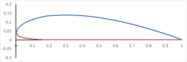
In questo esperimento, una galleria del vento viene utilizzata per generare determinate velocità dell'aria e un'ala Clark Y-14 con un lembo e una lamella viene utilizzata per raccogliere e calcolare dati, come il coefficiente di portanza, resistenza e momento di beccheggio. Un profilo alare Clark Y-14 è mostrato nella Figura 1 e ha uno spessore del 14% ed è piatto sulla superficie inferiore dal 30% della corda sul retro. Qui, i test in galleria del vento vengono utilizzati per dimostrare come le prestazioni aerodinamiche di un'ala Clark Y-14 siano influenzate da dispositivi ad alta portanza, come flap e lamelle.

Figura 1. Profilo del profilo alare Clark Y-14.
Procedura
- Per questa procedura, utilizzare una galleria del vento aerodinamica con una sezione di prova di 1 ft x 1 ft e una velocità massima di funzionamento di 140 mph. La galleria del vento deve essere dotata di un sistema di acquisizione dati (in grado di misurare angolo di attacco, forza normale, forza assiale e momento di beccheggio) e di un bilanciamento pungente.
- Aprire la sezione di prova e installare l'ala sulla bilancia della puntura. Inizia con una configurazione dell'ala pulita.
- Posizionare un inclinometro portati
Risultati
I risultati della configurazione dell'ala pulita sono mostrati nella Tabella 1. Le figure 6 - 8 mostrano tutti e tre i coefficienti rispetto all'angolo di attacco, α, per tutte e quattro le configurazioni. Dalla Figura 6, sia il lembo che la lamella hanno migliorato il coefficiente di sollevamento, ma in modi diversi. Confrontando l'ala pulita e la curva di sollevamento della lamella, le due curve si sovrappongono quasi a bassi angoli di attacco. La curva di sollevamento dell'ala pulita .
Applicazione e Riepilogo
La generazione di ascensori può essere migliorata dall'implementazione di dispositivi ad alto sollevamento, come alette e lamelle. La maggior parte degli aerei sono dotati di flap e tutti gli aerei da trasporto commerciale hanno sia flap che doghe. È fondamentale caratterizzare le prestazioni di un'ala con alette e lamelle durante lo sviluppo dell'aeromobile.
In questa dimostrazione, un'ala Clark Y-14 con un flap e una lamella è stata valutata in una galleria del vento. Le misure delle forz...
Riferimenti
- John D. Anderson (2017), Fundamentals of Aerodynamics, 6th Edition, ISBN: 978-1-259-12991-9, McGraw-Hill
Vai a...
Video da questa raccolta:

Now Playing
Clark Y-14 Wing Performance: implementazione di dispositivi ad alto sollevamento (flap e lamelle)
Aeronautical Engineering
13.4K Visualizzazioni

Prestazioni aerodinamiche di un aeromodello: il DC-6B
Aeronautical Engineering
8.3K Visualizzazioni

Caratterizzazione dell'elica: variazioni di passo, diametro e numero di pale sulle prestazioni
Aeronautical Engineering
26.4K Visualizzazioni

Comportamento del profilo alare: distribuzione della pressione su un'ala Clark Y-14
Aeronautical Engineering
21.1K Visualizzazioni

Metodo della sfera di turbolenza: valutazione della qualità del flusso nella galleria del vento
Aeronautical Engineering
8.7K Visualizzazioni

Flusso cilindrico incrociato: misurazione della distribuzione della pressione e stima dei coefficienti di resistenza
Aeronautical Engineering
16.2K Visualizzazioni

Analisi degli ugelli: variazioni del numero di Mach e della pressione lungo un ugello convergente e un ugello convergente-divergente
Aeronautical Engineering
37.9K Visualizzazioni

Schlieren Imaging: una tecnica per visualizzare le caratteristiche del flusso supersonico
Aeronautical Engineering
11.5K Visualizzazioni

Visualizzazione del flusso in un tunnel d'acqua: osservazione del vortice di estremità su un'ala delta
Aeronautical Engineering
8.1K Visualizzazioni

Visualizzazione del flusso di colorante superficiale: un metodo qualitativo per osservare le linee di flusso nel flusso supersonico
Aeronautical Engineering
4.9K Visualizzazioni

Tubo Pitot-statico: un dispositivo per misurare la velocità del flusso d'aria
Aeronautical Engineering
48.8K Visualizzazioni

Anemometria a temperatura costante: uno strumento per studiare il flusso turbolento dello strato limite
Aeronautical Engineering
7.2K Visualizzazioni

Trasduttore di pressione: calibrazione mediante tubo statico Pitot
Aeronautical Engineering
8.5K Visualizzazioni

Controllo di volo in tempo reale: calibrazione del sensore incorporato e acquisizione dati
Aeronautical Engineering
10.2K Visualizzazioni

Aerodinamica multirotore: caratterizzazione della spinta su un esacottero
Aeronautical Engineering
9.1K Visualizzazioni