
Aby wyświetlić tę treść, wymagana jest subskrypcja JoVE. Zaloguj się lub rozpocznij bezpłatny okres próbny.
Method Article
Novel 3D/VR Interactive Environment for MD Simulations, Visualization and Analysis
W tym Artykule
Podsumowanie
A new computational system featuring GPU-accelerated molecular dynamics simulation and 3D/VR visualization, analysis and manipulation of nanostructures has been implemented, representing a novel approach to advance materials research and promote innovative investigation and alternative methods to learn about material structures with dimensions invisible to the human eye.
Streszczenie
The increasing development of computing (hardware and software) in the last decades has impacted scientific research in many fields including materials science, biology, chemistry and physics among many others. A new computational system for the accurate and fast simulation and 3D/VR visualization of nanostructures is presented here, using the open-source molecular dynamics (MD) computer program LAMMPS. This alternative computational method uses modern graphics processors, NVIDIA CUDA technology and specialized scientific codes to overcome processing speed barriers common to traditional computing methods. In conjunction with a virtual reality system used to model materials, this enhancement allows the addition of accelerated MD simulation capability. The motivation is to provide a novel research environment which simultaneously allows visualization, simulation, modeling and analysis. The research goal is to investigate the structure and properties of inorganic nanostructures (e.g., silica glass nanosprings) under different conditions using this innovative computational system. The work presented outlines a description of the 3D/VR Visualization System and basic components, an overview of important considerations such as the physical environment, details on the setup and use of the novel system, a general procedure for the accelerated MD enhancement, technical information, and relevant remarks. The impact of this work is the creation of a unique computational system combining nanoscale materials simulation, visualization and interactivity in a virtual environment, which is both a research and teaching instrument at UC Merced.
Wprowadzenie
Materials science is an interdisciplinary field that examines the structure-property relationships in matter for their application to many areas of science and engineering. As structure-property relationships are investigated through computer simulations in addition to experimentation, computational tools offer complementary features that can enhance research efforts. While nanomaterials are of interest to scientists and have redeeming value for their potential social impact, this size regime is fraught with many challenges found particularly in experimentation.
Computer simulations allow scientists and engineers to perform specialized tests in a large variety of environments limited only by time and computational resources. Molecular dynamics (MD) simulations allow the appropriate time and length scales to study the phenomena of interest in many nanomaterials. Simulations expand the study of materials by removing the constraints of the physical laboratory, however many computational tools lack accessible, intuitive interfaces for research. Enhancement with the graphical display of models, efficient computational algorithms, and graphical processing unit (GPU) based computing complement current simulation efforts. These new graphics devices combine with central processing units efficiently to allow mathematically intensive calculations to be accomplished by the GPU. The result is an effective acceleration of computation on the order of 10x accompanied by a reduction in power consumption of up to 20x.
The goal of this research project was to develop and implement a novel tool for nanoscience investigation that directly connects an interactive interface to MD simulations, materials science analysis and 3D visualization. This innovative system with unique and powerful analysis capabilities has been used for nanoscale research and education at UC Merced, with direct implications to other related STEM fields such as nanotechnology, physics, biology, and geology, and ultimate benefit to education and society.
The 3D/VR Visualization System was implemented as both a research and teaching instrument which allows creation and manipulation of atomic structures in an interactive 3D virtual reality (VR) environment. The system was created from a set of relatively low-cost and accessible components following the model originally developed by Dr. Oliver Kreylos at UC Davis1.
Below is a photo of the final 3D/VR Visualization System layout, with important components labeled (Figure 1). This system was originally established for education purposes at UC Merced in 2009. The implementation of the original 3D/VR system resulted in peer-reviewed publications2-3. Table 1 below summarizes key characteristics for each element of the 3D/VR Visualization System.

Figure 1. 3D/VR Visualization System and main components (left) in the Davila Research Laboratory at UCM and visualization devices (right). Please click here to view a larger version of this figure.
| Item | Component | Functionality in System |
| A | 3D TV | 3D display of modeled molecular structures and on-screen menus. |
| B | Infrared (IR) tracking cameras4 | IR cameras track positions of the Wiimote and 3D viewing goggles in the user workspace in front of 3D TV, allowing virtual 3D manipulation of displayed structures. |
| C | Tracking PC | Runs IR camera tracking software and transmits Wiimote and 3D goggle positions to modeling computer. |
| D | Wiimote | Used for on-screen management of modeling software and to manipulate structures in 3D virtual environment. |
| E | 3D goggles5 | Synchronized with 3D TV IR signal, allow 3D view of structure. Position tracked by IR cameras for accurate 3D view. |
| F | Modeling PC | Runs NCK/VRUI 3D modeling and display software6, accepts goggle / Wiimote position and control signals to create accurate 3D molecular structure view. |
Table 1. Functionality of main elements of the 3D/VR Visualization System at UCM.
Description of 3D/VR Visualization System and Basic Components:
3D/VR Visualization System Overview — The 3D/VR Visualization System consists of a set of IR cameras and tracking software operating in conjunction with 3D modeling software to allow a user to interactively create 3D molecular structures. The IR cameras and software track the 3D location of a Wiimote and 3D viewing goggles using IR markers, and pass this to the modeling software. The modeling software uses the Wiimote control signals and movement to generate 3D molecular structures viewable using the combination of a 3D-capable large format television with synchronized and tracked 3D goggles. This results in a 3D virtual reality workspace within which the user can dynamically create and manipulate virtual molecular structures which reflect real-world physical behavior based on inter-atomic forces used in the modeling software (Figure 2). Special considerations for setting up this system can be found in supplemental materials.

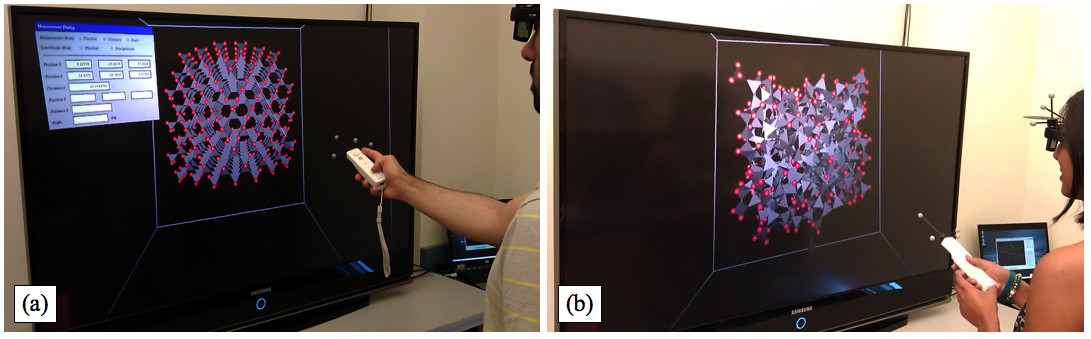
Figure 2. Investigating silica nanomaterials using the 3D/VR Visualization System. (a) A researcher creates an initial cristobalite model (crystalline) before GPU-based simulations. (b) Upon performing a simulated MD melt-quench procedure on model shown in (a), another researcher obtains a silica glass model (non-crystalline). Please click here to view a larger version of this figure.
3D/VR Visualization System Enhancement — MD Simulation Capability:
Molecular dynamics simulation systems are commonly implemented in a multi-nodal fashion, that is, a large workload is distributed or parallelized among tens to thousands of processors. Recently, additional opportunities for accelerated scientific computing have arisen out of developments in computer graphics processing. These advances include a software interface allowing scientists to take advantage of the highly parallel nature of the processing power intrinsic to graphics chips. With the advent of the Compute Unified Device Architecture or CUDA7, scientists can use GPUs8 to enhance the speed at which problems are solved while reducing the cost of infrastructure. A typical GPU may have the equivalent of hundreds to thousands of cores or “nodes” for processing information, and as these can each be used in parallel, a well-coded solution may provide up to 1,000x throughput acceleration against its multi-core counterpart. Though not every problem is well-suited to this approach, current MD simulations have seen up to 15x throughput performance gains9. Details on the 3D/VR visualization system MD-GPU enhancement can be found in supplemental materials.
Protokół
1. Install 3D/VR Modeling Software on Modeling PC
- Install LINUX base operating system on modeling PC (Ubuntu x86 / AMD64 depending on hardware).
- Modify LINUX base operating system.
- Install libraries and add functionality as necessary.
- Install VRUI and NCK 3D/VR modeling software on Modeling PC6.
- Check related websites1,6 to obtain latest versions of all modeling software components.
- Compile, configure and test VRUI.
- Install and test NCK.
2. Set Up Tracking System1
- Mount IR Tracking Cameras4
- Create a rigid camera suspension frame directly above the front edge of the 3D TV near the ceiling for best coverage. Mount 3 cameras on swivel mounts directly above the front corners and the front center of the 3D TV. Ensure that the coverage angle of each camera just grazes the front surface of the TV.
- Aim the cameras to have the widest coverage angle (45 degrees) parallel to the front of the 3D TV. Use a narrower coverage angle (30 degrees) perpendicular to the front of the 3D TV. Allow for maximum overlap within the desired 3D working space. Ensure objects are in view of at least two cameras to be tracked successfully (Figure 3).

Figure 3. IR tracking camera coverage to maximize 3D workspace in front of TV. Parts (A) and (B) show front and side view with respect of the 3D/VR Visualization System. Please click here to view a larger version of this figure.
- Experiment with alternate camera placement if required to create an adequate 3D workspace. This may be required if the vertical camera mounting distance is constrained.
- Install and Calibrate Tracking Software
- Install the OptiTrack Rigid Body Toolkit on the tracking computer using included installation manual.
- Set Threshold, Exposure, Illumination values dependent on environment and set the Capture Quality to high, as detailed in the tracking software instructions.
- For the Wand Capture, be careful to remove all other reflective material from the 3D workspace. Move smoothly throughout camera overlap working area with the reflective wand. Repeat until standard and mean errors below “0.5” are obtained then save the calibration file.
- Set the ground plane to establish a tracked 3D work area coordinate system origin. Define the Wiimote and 3D goggle tracked objects as detailed in the tracking software instructions.
- Complete VRUI Calibration
- Set VRUI to accept tracking information from tracking computer.
- Verify tracking functionality in VRUI using DeviceTest calibration utility.
- Align VRUI 3D display and tracking software coordinate systems.
- Set orientation of tracked Wiimote and 3D goggles using AlignTrackingMarkers alignment software.
3. Prepare 3D Modeling System for Use
- Before beginning, remove all reflective jewelry (i.e., watches, earrings, metals, etc.). Do not remove corrective glasses needed to focus on the screen.
- Assemble the equipment for the 3D/VR Visualization System:
- Modeling computer
- Tracking computer
- Large format 3D-capable TV
- Video cable between modeling computer and 3D TV
- 3D IR emitter for 3D TV
- Ethernet cables for modeling and tracking computers
- Wiimote with tracking antlers (controller)
- 3D goggles with tracking antlers (3D goggles)5
- Carefully place controller where it can be reached easily from modeling computer, taking care not to touch or move the spherical IR tracking markers attached to it.
- Carefully place 3D goggles on TV stand (as before, be sure to avoid touching the reflective markers).
- Connect the three USB cables from the IR cameras mounted above the 3D TV to 3 USB ports on the tracking computer, while it is powered OFF.
- Locate the 3D TV remote control and place it in front of 3D TV.
- Connect the video cable to the video card on the modeling computer and the video input of the 3D TV. Also connect the 3D IR emitter for the 3D synchronizing output from the 3D TV, and place emitter on TV stand near side of TV, pointing up toward where goggles will be used. BE VERY CAREFUL NOT to shift the position of the calibrated TV.
- Turn 3D TV ON before powering on the modeling computer to ensure proper recognition by the computer.
- Turn ON modeling computer. After the modeling computer boots to a login prompt, log in on the modeling computer LINUX system to an appropriate account.
- Once the modeling computer desktop is available, use the 3D TV remote control to check the status of the video cable connection by pressing the “info/i” button. Ensure that the TV screen displays “1920x1080 @ 60hz” in the upper left corner. If not, reboot the modeling computer to establish correct recognition of the 3D TV. Also be sure TV is in 3D output MODE 2, using the remote control setup menus.
- On the modeling computer desktop, open a terminal window with several tabs.
- On the tracking computer, verify the ethernet adapter IP address by typing “ipconfig” in a command window.
- On the modeling computer, open a terminal window tab and check within the VRDevices.cfg file that the “serverName” defines the tracking computer ethernet adapter IP address.
- If necessary, alter the “serverName” IP address in VRDevices.cfg to match the tracking computer ethernet adapter, and save VRDevices.cfg.
- On the tracking computer, initiate the OptiTrack Rigid Body Tool software.
- Allow the software to open completely, then click the large button near the top menu labeled “Load Calibration Result”.
- Browse to and open the appropriate camera calibration file.
- After the file is loaded, click the “File” menu and select “Load rigid body definitions”.
- Browse to and open the appropriate rigid body definition file for the tracked controller and 3D goggles.
- On the rightmost pane of the tracking software, locate the section labeled “Streaming”, expand the section and under the “VRPN Streaming” category, verify that the port number listed is 3883, then check the “Broadcast frame data” box inside the “VRPN Streaming Engine” category.
- At the modeling computer, make sure that the controller is either directly in hand or immediately reachable (2 sec away at the most).
- On the modeling computer, bring up a tab in the terminal window created earlier in this session and navigate to and then initiate the VRDeviceDaemon software, e.g., typing “./VRDeviceDaemon”.
- Follow the prompt to “press buttons 1 & 2 on the Wiimote simultaneously.” If the activity was successful, the window will now display “VRDeviceServer: Waiting for client connection”.
4. Test 3D/VR Visualization System Using NCK Software
The following set of instructions outlines how to use the NCK software on-screen menus to establish controller tool functions, and then how to build and manipulate a carbon nanotube in the 3D/VR workspace from constituent carbon atoms (Figure 4). Instructions on how to measure the resulting bond angles and distances (Step 4.4.10) are available online10.

Figure 4. Undergraduate student using the 3D/VR Visualization System to study carbon nanotubes (CNTs). Photos (A)-(F) show the building process of a single-walled CNT. Please click here to view a larger version of this figure.
- Within the modeling computer terminal window created in Step 3.11, select the third tab. To initiate the NCK software, navigate to the NCK installation directory and type:
“./NanotechConstructionKit -rootSection localhost -domainsize 36”. - Being very careful not to touch or loosen the attached tracking markers, put on 3D goggles and pick up the controller. Adjust head/goggle viewing position to ensure 3D goggles are receiving 3D TV IR emitter sync signal, allowing 3D/VR viewing of TV display.
- In order to have a toolset to add, move and delete atoms, assign NCK command associations to buttons on the controller as follows:
- Bring up the main NCK on-screen menu by pressing and holding the Home button on the Wiimote, navigating to and selecting the “Override Tools” menu item, then releasing the Home button. This allows assignment of commands to different buttons on the controller independently of one another.
- To associate the Wiimote trigger button (on the bottom of the controller) with the action of manipulating atoms within NCK, press and hold the trigger button, navigate the on-screen NCK menu to “Dragger” and select “6-DOF Dragger,” then release the trigger. The trigger is now associated with the action of manipulating the atoms.
- To assign the function of adding an atom to the “+” button on the Wiimote, bring the main menu up by pressing and holding the Home button, navigate to “Structural Unit Types”, and select “Triangle”, then release the Home button.
- Next press and hold the “+” button, navigate to “Dragger,” and select “6-DOF Dragger,” then release the “+” button. The “+” button is now associated with creating new atoms of the type selected (carbon atoms represented by triangles, in this case).
- To assign the function of deleting an atom to the “-” button on the Wiimote, bring up the main menu by pressing and holding the “Home” button, then navigate to “Structural Unit Types,” and select “Delete Selected Units,” then release the Home button.
- Next, press and hold the “-” button, navigate to “Dragger,” then “6-DOF Dragger,” and release the “-“ button. The “-” button is now associated with deleting atoms.
- Follow a similar procedure to assign the functions of “Lock Selected Units” to the “1” Wiimote button, and “Unlock Selected Units” to the “2” controller button.
- Once the controller buttons have been configured, create a carbon nanotube using NCK as follows:
- Using the “+” button, add two 3-bond triangular carbon atoms to the NCK workspace. Manipulate these using the trigger button until they join at a vertex.
- Add 4 more carbon atoms to create a hexagonal star shape.
- Using the “Home” menu, navigate to “I/O Menus”, then “Save Units .
- Move the 6 pointed structure away from its current position.
- Using the “Home” menu, navigate to “I/O Menus”, then “Load Units .
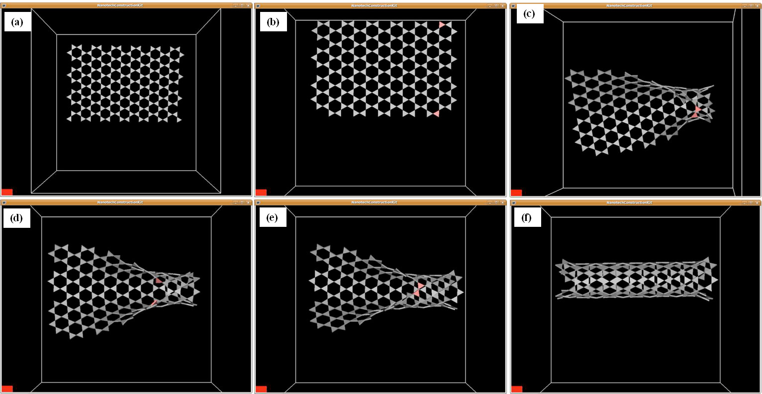
- Repeat the last 2 steps until a 6 by 6 sheet of hexagonal 6-atom rings has been created (Figure 5A).
- Using the “1” button, lock one atom in the top row, and an opposing atom in the bottom row. The locked atoms will be marked with a pink color (Figure 5B).
- Using the trigger button, carefully move one of the locked atoms in a circular arc until its free vertex approaches the free vertex of the opposing locked atom. A green line will appear between the vertices when they are close enough that atomic attraction will cause them to join with a bond (Figure 5C). Once successfully joined, unlock both of the atoms using the “2” button.
- Continue similarly locking, joining, and unlocking opposing atomic vertices in the carbon sheet, effectively “zipping” the sheet into a final carbon nanotube (Figures 5D-5F).

Figure 5. Step-wise creation of a single-walled CNT showing (A) a 6 x 6 sheet (graphene) of hexagonal carbon rings, (B) opposing carbon atoms “locked” (shown as pink triangles) to allow easier manipulation against realistic interatomic forces, (C) carbon (graphene) sheet carefully curved to allow bonding between atoms on opposing sides, (D) two additional opposing carbon atoms locked to assist further carbon sheet curvature, (E) additional opposing carbon atoms bonded to continue carbon sheet curvature into a nanotube, and (F) final CNT formed after sequential bonding of opposing atoms of the original carbon sheet (graphene). Please click here to view a larger version of this figure. - When the nanotube is complete, use on-screen measurement tools to confirm structural angles and distances10.
5. Visualization of Molecular Dynamics Simulation Models
- Import an initial crystalline SiO2 cubical model into the 3D/VR NCK software, and investigate the initial structure (see Figure 2A).
- Open-source programs MDCASK11 and LAMMPS12 were targeted because of features that are well-suited to this research focus. The latter program is used in this work given its varied interatomic potentials and GPU computing capability. Using the LAMMPS MD package12, run a simulated melt/quench procedure on this initial structure to produce an amorphous SiO2 structure. Details on this simulated procedure can be found in previous publications13-15.
- Import the resulting new amorphous (disordered) SiO2 model into the 3D/VR NCK software and investigate the structure (see Figure 2B).
- Create a SiO2 nanospring/nanoribbon out of the new amorphous solid using the open source code NanospringCarver16 and associated instructional documentation17 (Figure 6).

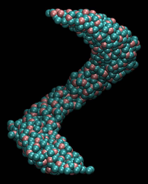
Figure 6. Illustration of the step-by-step atom selection process at different stages in the creation of a nanospring using the NanospringCarver program. Parts (A-D) indicate 25%, 50%, 75% and 100% completion of this process17. Please click here to view a larger version of this figure. - Use the LAMMPS MD package to perform tensile simulations on the nanospring/nanoribbon (Figure 7). Details on this procedure can be found in a previous publication15.

Figure 7. Snapshot image from LAMMPS MD silica helical nanostructure (nanoribbon) tensile simulation results. - Use the open source software tools VMD (Visualize Molecular Dynamics)18 ImageMagick19, and FFmpeg20 to create snapshots and animation of the helical nanostructure throughout this simulation (Animated Figure 1), for presentation in the 3D/VR Visualization System. Please click here to view a larger version of this figure.
Animated Figure 1. Animation of helical nanostructure tensile simulation.
Wyniki
This 3D/VR Visualization System presents new opportunities for conducting materials science studies. As this immersive environment operates in real time, in the form of 3D input and display, the researcher is presented with a fully interactive nanoscaled instrument2. By following the protocol presented here, a silica helical nanoribbon was created in this step-by-step fashion. A snapshot of this structure produced from LAMMPS MD is shown in Figure 7. This structure was subjected to simulated t...
Dyskusje
Critical elements in the successful installation and usage of the 3D/VR Visualization System are detailed in the Physical Environment and Design Considerations and Special Considerations in supplemental materials. Important installation considerations include 3D display height for comfortable long-term standing or seated usage, maximized tracking camera mounted height to create a large 3D working area, stable tracking camera and 3D display support to maintain configuration over time, and...
Ujawnienia
The authors declare that they have no competing financial interests.
Podziękowania
We wish to gratefully acknowledge the original inspiration and extensive support provided to us toward the creation of this system from Dr. Oliver Kreylos of the UC Davis Institute for Data Analysis and Visualization. His advice and assistance were instrumental to our success.
We also wish to thank the NSF BRIGE program for providing funding for this project. This material is based upon work supported by the National Science Foundation under Grant No. 1032653.
Materiały
| Name | Company | Catalog Number | Comments |
| Samsung 61" 3D-capable high definition DLP TV | Samsung | http://www.samsung.com/us/video/tvs | See Protocol Section 3 (Step 3.2) (Large format 3D-capable TV) |
| Alienware Area51 750i modeling computer | Alienware | http://www.alienware.com | See Protocol Section 1 (Step 1.1) (Modeling computer) |
| HP EliteBook 8530w tracking computer | HP | http://www.hp.com | See Protocol Section 2 (Step 2.3) (Tracking computer) |
| V100:R2 IR tracking cameras (3) | Naturalpoint | http://www.naturalpoint.com/optitrack/products/v100-r2/ | See Protocol Section 2 (Step 2.1) and Reference [4] (Tracking cameras) |
| OptiTrack Tracking Tools IR tracking software | Naturalpoint | http://www.naturalpoint.com/optitrack/software/ | See Protocol Section 2 (Step 2.3) and Reference [4] (Tracking software) |
| 3D Goggles and 3D TV IR sync emitter | Ilixco | http://www.i-glassesstore.com/dlp3d-wireless-2set.html | See Protocol Section 3 (Step 3.2) and Reference [5] (3D goggles) |
| Wiimote 3D controller | Nintendo | http://www.nintendo.com/wii | See Protocol Section 3 (Step 3.2) (Wiimote) |
| VRUI, NCK and associated 3D/VR modeling software | Open source software | http://idav.ucdavis.edu/~okreylos/ResDev/NanoTech/index.html | See Protocol Section 1 (Step 1.3) and References [1,6] (VRUI, NCK) |
| LAMMPS molecular dynamics software | Open source software | http://lammps.sandia.gov/ | See Protocol Section 5 (Step 5.2) and Reference [12] (LAMMPS) |
| NanospringCarver program code and files | UC Merced - open source | http://tinyurl.com/qame8dj | See Protocol Section 5 (Step 5.4) and References [16-17] (NanospringCarver) |
| MATLAB GUI files | UC Merced - open source | http://tinyurl.com/qame8dj | See Protocol Section 5 (Step 5.4) and References [16-17] (NanospringCarver) |
| Atomistic bulk glass input file | UC Merced - open source | http://tinyurl.com/qame8dj | See Protocol Section 5 (Step 5.4) and References [16-17] (NanospringCarver) |
Odniesienia
- Doblack, B. N., Flores, C., Matlock, T., Dávila, L. P. The emergence of immersive low-cost 3D virtual reality environments for interactive learning in materials science and engineering. Mater. Res. Soc. Symp. Proc. 1320, (2011).
- Flores, C., Matlock, T., Dávila, L. P. Enhancing materials research through innovative 3D environments and interactive manuals for data visualization and analysis. Mater. Res. Soc. Symp. Proc. 1472, (2012).
- . 3D goggle source. , (2013).
- . “3D/VR Visualization System - Startup and Shutdown Protocol” and “3D/VR Visualization System – CNT Modeling Example” documents Available from: https://eng.ucmerced.edu/people/ldavila/home/3d-vr-visualization-system-dissemination-of-research-results-and-products (2013)
- . MDCASK molecular dynamics code Available from: https://asc.llnl.gov/computing_resources/purple/archive/benchmarks/mdcask (2013)
- Feuston, B. P., Garofalini, S. H. Empirical three-body potential for vitreous silica. J. Chem. Phys. 89 (9), 5818-5824 (1988).
- Dávila, L. P., et al. Transformations in the medium-range order of fused silica under high pressure. Phys. Rev. Lett. 91 (20), 2055011-2055014 (2003).
- Doblack, B. N. . The structure and properties of silica glass nanostructures using novel computational systems. , (2013).
- Meagher, K. A., Doblack, B. N., Ramirez, M., Dávila, L. P. Scalable nanohelices for predictive studies and enhanced 3D visualization. J. Vis. Exp. In-Press, .
- . University of California Television (UCTV). Our Digital Life series: The Future: Teaching and Life-Saving Tools episode. , (2013).
Przedruki i uprawnienia
Zapytaj o uprawnienia na użycie tekstu lub obrazów z tego artykułu JoVE
Zapytaj o uprawnieniaThis article has been published
Video Coming Soon
Copyright © 2025 MyJoVE Corporation. Wszelkie prawa zastrzeżone