Method Article
Flame Experiments at the Advanced Light Source: New Insights into Soot Formation Processes
In This Article
Summary
Gas sampling from laboratory-scale flames with online analysis of all species by mass spectrometry is a powerful method to investigate the complex mixture of chemical compounds occurring during combustion processes. Coupled with tunable soft ionization via synchrotron-generated vacuum-ultraviolet radiation, this technique provides isomer-resolved information and potentially fragment-free mass spectra.
Abstract
The following experimental protocols and the accompanying video are concerned with the flame experiments that are performed at the Chemical Dynamics Beamline of the Advanced Light Source (ALS) of the Lawrence Berkeley National Laboratory1-4. This video demonstrates how the complex chemical structures of laboratory-based model flames are analyzed using flame-sampling mass spectrometry with tunable synchrotron-generated vacuum-ultraviolet (VUV) radiation. This experimental approach combines isomer-resolving capabilities with high sensitivity and a large dynamic range5,6. The first part of the video describes experiments involving burner-stabilized, reduced-pressure (20-80 mbar) laminar premixed flames. A small hydrocarbon fuel was used for the selected flame to demonstrate the general experimental approach. It is shown how species’ profiles are acquired as a function of distance from the burner surface and how the tunability of the VUV photon energy is used advantageously to identify many combustion intermediates based on their ionization energies. For example, this technique has been used to study gas-phase aspects of the soot-formation processes, and the video shows how the resonance-stabilized radicals, such as C3H3, C3H5, and i-C4H5, are identified as important intermediates7. The work has been focused on soot formation processes, and, from the chemical point of view, this process is very intriguing because chemical structures containing millions of carbon atoms are assembled from a fuel molecule possessing only a few carbon atoms in just milliseconds. The second part of the video highlights a new experiment, in which an opposed-flow diffusion flame and synchrotron-based aerosol mass spectrometry are used to study the chemical composition of the combustion-generated soot particles4. The experimental results indicate that the widely accepted H-abstraction-C2H2-addition (HACA) mechanism is not the sole molecular growth process responsible for the formation of the observed large polycyclic aromatic hydrocarbons (PAHs).
Introduction
Establishing a consistent and predictive mechanism for molecular growth and soot formation processes is one of the greatest challenges in combustion chemistry research8,9. Combustion processes account for over half of the fine particle air pollution (PM2.5 – fine particles defined by an aerodynamic diameter of ≤2.5 μm), and, to reduce the emission of these unwanted combustion byproducts, it is important to know their identities, concentrations, and formation pathways10. The nature of the combustion byproducts is influenced by the fuel and the conditions under which it is burned. Many studies have linked combustion emissions to acute environmental and health effects11-13. For example, combustion-generated particles have a strong influence on the air quality, atmospheric visibility, and the radiative balance of the Earth’s atmosphere. It is assumed that the chemical composition of the airborne combustion-generated particles determines their toxicity, which is commonly associated with polycyclic aromatic hydrocarbons (PAHs). The latter species are considered to be the molecular precursors of soot, and they are formed in incomplete combustion processes. Again, to identify these processes is still a challenging problem.
Generally speaking, the combustion reactions, which are at the origin of these emissions, follow complicated fuel decomposition and oxidation pathways, involving many different reactive species. They are connected within a network of hundreds or even thousands of reactions whose rates depend on temperature and pressure14,15.
Laminar, premixed, burner-stabilized flat flames, which can be established at pressures as low as 20-80 mbar (15-60 Torr), represent one of the standard combustion environments commonly used to unravel this complex chemical network and to investigate the pollutant potential of any given prototypical fuel16. In this configuration, the fuel and the oxidizer are already mixed when they reach the flame front; thus, the rate of combustion is dominated by chemical processes and not by mixing. By operating these flames at a sub-atmospheric pressure, the physical thickness of the reaction region is increased, allowing for improved spatial resolution of temperature and concentration gradients with laser-based or probe-sampling techniques1,17.
In order to precisely analyze the chemical composition of such flames, an analytical tool is required that provides universal detection of all species simultaneously, high sensitivity and dynamic range, good selectivity between isomers, and control of molecular fragmentation. A breakthrough in combustion-chemistry research was achieved with the use of flame-sampling mass spectrometry at synchrotron light sources where tunable vacuum-ultraviolet (VUV) radiation is used for near-threshold single-photon ionization5,6. In the flame experiments at the Advanced Light Source (ALS) of the Lawrence Berkeley National Laboratory, which are shown in the accompanying video, gas samples are withdrawn from within the premixed flames by a quartz cone, expanded into higher vacuum, and ionized by VUV photons1,5. The experimental set-up is shown schematically in Figure 1. The key to the success of this experiment has been the ability to tune the energy of the ionizing photons in an appropriate range to minimize or even avoid photofragmentation and to allow isomer specificity1,3,5,18. As shown in the video, photoionization efficiency (PIE) curves can be recorded by tuning the photon energy19, which allow us to identify specific isomeric species in the complicated flame mixture. The PIE curves for individual species generally have distinct features, i.e., ionization thresholds, shapes, and intensities. The video also shows the experimental approach used to determine mole-fraction profiles of the individual components as a function of the distance to the burner surface.
These ALS-based combustion experiments have been focused on soot-formation processes in hydrocarbon flames and on the oxidation of oxygenated, next-generation, bio-derived fuels1,20. With regards to the soot-formation problem, the experiments revealed many new insights. In summary, it is now understood that the chemical structure of the fuel influences the identity (and the quantity) of the precursor molecules and that consequently many different pathways can contribute to the first step of the overall soot-formation process7,21.
Even deeper insights into the soot-formation chemistry were gained when identifying the chemical components of flame-generated soot nanoparticles with an ALS-based aerosol mass spectrometer. In this new experiment, which is explained in the second half of the video, non-premixed (diffusion) flames are used. The experimental setup is also shown in Figure 1. In this configuration, a flame is established at near-atmospheric pressure [933 mbar (700 Torr)] between two opposed laminar jets of fuel and oxidizer. Because the fuel and oxidizer streams remain separated outside the reaction zone, this configuration provides a good opportunity to examine molecular growth processes. Flame-generated particles are withdrawn from the flame using a quartz microprobe and subsequently focused with an aerodynamic lens system onto a heated copper target, where the particles flash vaporize and break apart into their individual constituents. These molecular building blocks are then ionized by the VUV photons from the ALS, and the corresponding ions are mass selected4. Not all the necessary work can be shown in the video, but the aerosol data suggest that the soot-formation mechanisms might be kinetically and not thermodynamically controlled. Furthermore, the data also indicate that the widely accepted H-abstraction-C2H2-addition (HACA) mechanism, in which small aromatic species grow to larger polycyclic aromatic hydrocarbons (PAHs) by a repetitive sequence of H-abstraction and C2H2-addition reactions, cannot explain all the observed particle constituents.
Combined with the video, the following protocol details the data acquisition procedures.
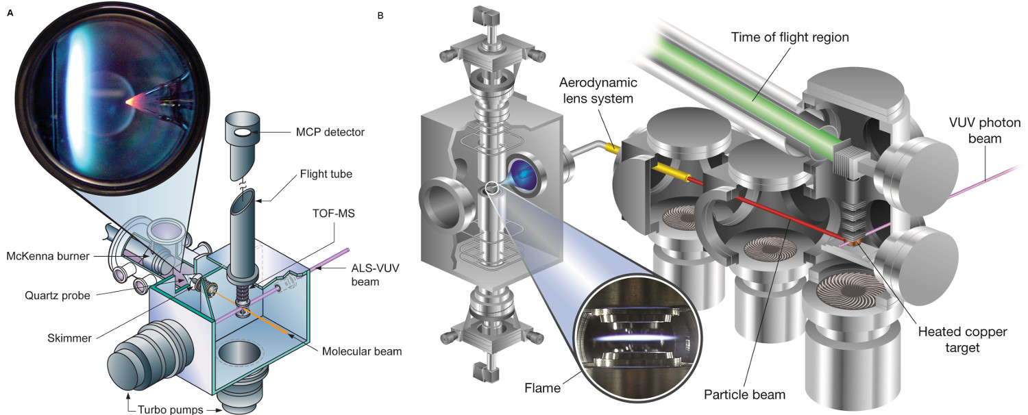
Figure 1. Schematic diagram of the flame-sampling molecular beam and aerosol mass spectrometry experiments at the Advanced Light Source of the Lawrence Berkeley National Laboratory. With permissions from Refs. 2 and 4. Please click here to view a larger version of this figure.
Protocol
1. Gas-phase Experiments
- Igniting the Low-pressure Premixed Flame
- Make sure that the cooling water is flowing through the burner and flame chamber wall and that the flame chamber is pumped down to ~0.1 mbar.
- Establish a 1 L/min flow of argon and a 1.5 L/min flow of oxygen through the burner surface and maintain a pressure of 80 mbar (60 Torr) in the flame chamber.
- Position the hot-wire igniter over the burner surface; set the hydrogen flow to 0.4 L/min, and quickly activate the igniter.
- After ignition, turn off the hot-wire igniter, and reposition it away from the burner.
- Establish the desired flows of argon, oxygen, hydrogen, and fuel. Adjust the pressure to match the conditions of the target flame [typically 20-40 mbar (15-30 Torr)]. Note: Flame conditions for individual flames are provided in the original literature. For example, flows for the stoichiometric allene and propyne flames are listed in Hansen et al22.
- Acquisition of Photoionization Efficiency (PIE) Curves – Energy Scan
- When the pressure in the ionization chamber is ≤10-6 mbar, apply the voltages to the ion optics of the time-of-flight mass spectrometer and microchannel plate detector and open the beamline valves. Note: Earlier calibration experiments (not shown in the video) were used to find the voltage settings for optimal performance of the mass spectrometer.
- Start the Labview data acquisition program “General Interface.vi” (Figure 2) and move the burner to the desired position using the “Motor” tab in the software. Note: This Labview code was developed at the beamline and is available upon request.
- Use the “General” tab to define the scan parameters, i.e., the number of steps per eV of photon energy. Typically, a step size of 0.05 eV is used.
- Use the “ALS” tab to set the photon energy to the desired start value, and define the “ALS Energy” to be “active”.
- On the “Control” panel, activate “K6485” to read out the photocurrent measured by the photodiode.
- On the “P7886” tab, use the “Set Parameters” button to set the number of sweeps (normally between 219 and 221), the number of bins (normally 48k), and the bin width (500 psec).
- Enter a valid file path and name, and click “Start” to start the computer-controlled data acquisition process.
- Acquisition of Mass Spectra – Burner Scan
- Apply the voltages as for the energy scans to the ion optics of the time-of-flight mass spectrometer and microchannel plate detector.
- Open the beamline valves to allow the photon beam in the chamber.
- Open the Labview data acquisition program “General Interface.vi”.
- Using the “Motor” tab in the software, use the “Jogger” to move the burner surface as close as possible to the sampling cone, and define that position as the “Origin”. Define the motor to be “active”.
- Use to “General” tab to define the scan parameters, i.e., the number of steps per mm of burner movement. Typical values are 0-5 mm in 20 steps, 5-20 mm in 15 steps, and 20-30 mm in 5 steps.
- Use the “ALS” tab to set the photon energy to the desired value. Typical values are 8-16.65 eV.
- On the “Control” panel, activate “K6485” to read out the photocurrent measured by the photodiode.
- On the “P7886” tab, use the “Set Parameters” button to start a sub-VI (Figure 3) to set the number of sweeps, i.e., the number of mass spectra added on top of each other at every burner position (normally between 219 and 221), the number of bins (normally 48k), and the bin width (500 psec).
- Provide a valid file path and name, and click “Start” to begin the automated data acquisition process.
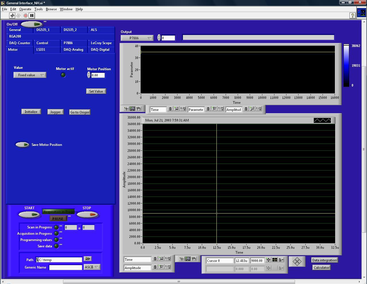
Figure 2. Graphical user interface of the data acquisition program. Please click here to view a larger version of this figure.
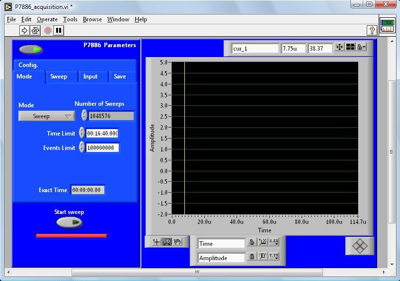
Figure 3. Graphical user interface to input multichannel scaler parameters. Please click here to view a larger version of this figure.
2. Aerosol Experiments
- Igniting the Near-atmospheric Pressure Opposed-flow Flame
- Make sure that the cooling water is flowing through the burner, that the reactant outlets are approx. 10 mm apart, and that the flame chamber is pumped down to the minimum achievable pressure (~2 mbar).
- Fill the flame chamber with argon and bring the pressure up to ~860 mbar (650 Torr).
- Place the igniter coil approx. in the center of the two burner outlets.
- Set the gas flows as follows (Ar should already be flowing because it was used to fill chamber): Oxidizer stream: O2 0.3 L/min and Ar 1.6 L/min; Oxidizer stream coflow: Ar 2.5 L/min; Fuel stream: H2 0.3 L/min, Ar 2.5 L/min; Fuel stream coflow: Ar 2.5 L/min.
- Open the hydrogen and oxygen valves, and immediately switch on igniter coil.
- Once the flame is ignited, turn off the igniter coil, and retract it.
- Establish the desired flows of oxygen, argon, and fuel. Turn off the flow of hydrogen, and set pressure and reactant outlet separation to desired values for target flame. Note: The flow rates for the propane flame, which is shown in the video, are provided in Skeen et al4.
- Acquisition of an Aerosol Mass Spectrum
- Apply the appropriate voltages to the ion optics and detector of the AMS. Note: The voltage settings for an optimal performance were found in earlier calibration experiments, which are not shown in the video.
- Open the Labview data acquisition program “General Interface-Opposed-Flow.vi”. Note: This VI is a modification of the “General Interface.vi”, in which the motor control has been updated to match the new needs.
- Use the “Jogger” application on the “Motor” tab to translate the opposed-flow burner so that the quartz microprobe is at the position nearest to the fuel stream outlet (Figure 4). While at this position, reset the motor step position to zero. This procedure defines the “origin” position.
- Slowly open the quarter-turn ball valve allowing flow from the flame-sampling line into the aerodynamic lens (ADL) system. Confirm that the pressure at the outlet of the ADL is near 1 x 10² mbar.
- Use the “General” tab to define the scan parameters, i.e., the number of steps per mm of burner movement (burner scan) or photon energy (energy scan).
- Use the “ALS” tab to set the desired photon energy, and use the “Motor” tab to move the burner to the desired burner position.
- Use the “P7886” tab and the “Set Parameters” button therein to set the acquisition parameters.
- Define “Motor” (burner scan) or “ALS Energy” (energy scan) to be “active”.
- Insert a valid file path and name in the appropriate fields, and click “Start”. Aerosol mass spectra are now automatically taken.
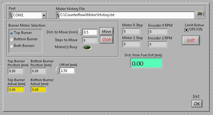
Figure 4. Graphical user interface for burner movement for the opposed-flow flame assembly. Please click here to view a larger version of this figure.
Results
A typical mass spectrum of flame-sampled gases from the low-pressure premixed burner is shown in Figure 5. The identities of the species contributing to the signal are revealed by the flame-sampled photoionization efficiency (PIE) curves for each mass-to-charge (m/z) ratio and their comparison to known isomer-specific ionization energies and PIE curves. Typical examples of flame-sampled PIE curves are shown in Figure 6 for m/z=39 (C3H3) and 41 (C3H5). The data are taken from a stoichiometric propyne flame22. The signal is unambiguously identified by their characteristic ionization thresholds to originate from the resonantly stabilized propargyl and allyl radicals. For many m/z values, multiple isomers are routinely identified by observing multiple thresholds. Many examples have been discussed extensively in the literature, for example, m/z=40 (allene and propyne), 44 (ethenol and acetaldehyde), 54 (1,3-butadiene, 1-butyne, and 2-butyne), or 78 (fulvene and benzene)23-27.
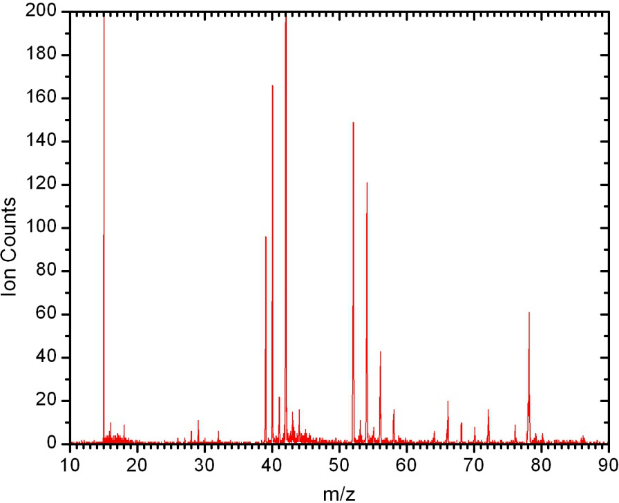
Figure 5. Time-of-flight mass spectrum. Recorded with photons of 9.9 eV at 1.25 mm distance from the low-pressure premixed burner in a stoichiometric propyne-O2 flame. All peaks can be easily assigned to various combustion intermediates as outlined in the next step.
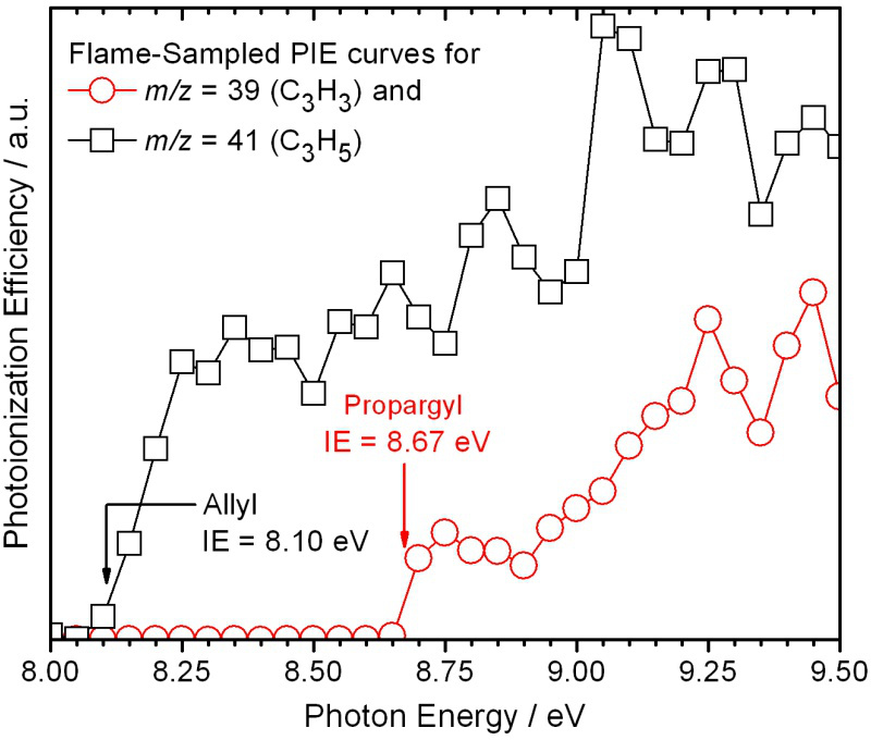
Figure 6. Flame-sampled photoionization efficiency curves for m/z=39 and 41. The resonantly stabilized radicals propargyl and allyl can unambiguously be identified based on the observed ionization thresholds.
Once the isomeric composition is known, mass spectra are taken at various photon energies and from within different positions in the flame, as described above in the Protocol Section, to allow for the determination of isomer-specific mole fraction profiles of the individual species as a function of distance from the burner surface. Representative mole-fraction profiles of fulvene and benzene in a stoichiometric propyne flame from the low-pressure premixed burner are shown in Figure 7 22. For each flame, typically a total of 40 to 50 individual mole-fraction profiles are determined for species ranging from m/z=1 (H atom) to m/z=78 (benzene and/or fulvene) or even higher, depending on the scientific goals. These mole fraction profiles are then used to assess the predictive capabilities of combustion-chemistry models and to validate them.
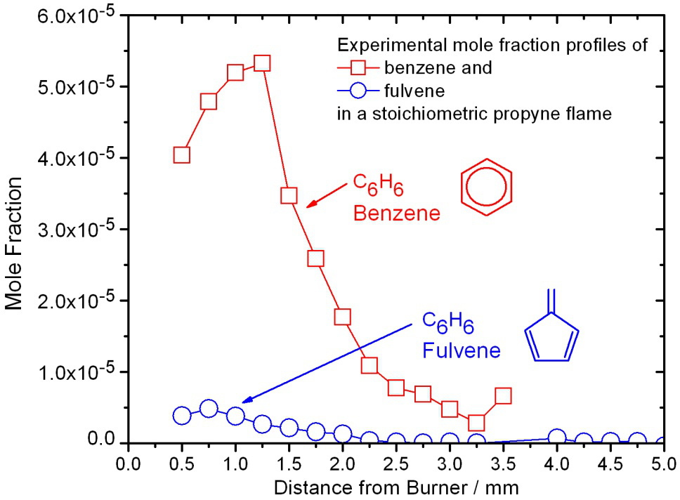
Figure 7. Experimental mole fraction profiles. Profiles of fulvene and benzene in a stoichiometric propyne flame from the low-pressure premixed burner.
A typical aerosol mass spectrum is shown in Figure 8. It was taken from within a propane opposed-flow diffusion flame. Ion signal was observed for species with m/z ratios ranging from 150 to 600, with a peak around m/z=226. It is beyond the current experimental capabilities to identify all of the species observed in the mass spectrum or to unravel their possible formation pathways. Taking such mass spectra as a function of distance from the fuel outlet as described above (and shown in the video) provides spatially resolved profiles. A representative example is shown in the inlet of Figure 8 for the m/z=256 (C20H16) species. Similar profiles can be obtained for any of the other species as well, which consequently could be used as validation targets for any combustion-chemistry model.
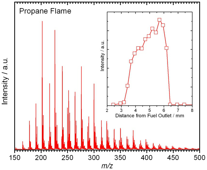
Figure 8. Flame-sampled aerosol mass spectrum from a propane-O2 opposed-flow diffusion flame. The inlet shows a representative spatially resolved profile for the C20H16 species at m/z=256.
Discussion
The described combination of flame-sampling and synchrotron-based VUV single-photon ionization with mass spectrometry provides the most detailed look into the chemical composition of laboratory-based model flames currently possible. The mass spectrometer provides universal detection of all sampled flame species simultaneously with high sensitivity (ppm range) over a wide dynamic range. Instrumental for the success of this technique is the use of synchrotron-generated VUV photons, whose energies can easily be tuned, to provide good selectivity between isomers and control of fragmentation. The latter factor is important when analyzing complex mixtures. The capabilities of the described experiment are unmatched by gas chromatography, which is commonly used for isomer-separation, and by conventional ionization techniques using energetic electrons. Limitations of the synchrotron-based technique arise from the fact that, especially for larger mass-to-charge ratios, many different isomers are conceivable, which then cannot be uniquely identified, and their contributions cannot be separated reliably1. The experimental results, in the form of isomer-resolved flame compositions, may yield improved kinetic models of combustion chemistry at an exceptionally detailed molecular level.
The described experiments are very complicated and a description of the troubleshooting procedures is beyond of what can be documented in the video and/or the protocol section of this manuscript. This fact is also true for the data analysis procedures. Modifications to the experimental set-up are normally done off-line in between the allocated “beamtime”. Because the emphasis of these experiments is on the quantitative determination of combustion intermediates, it is very critical to have stable and reproducible flames. Furthermore, it is necessary to wisely choose the photon energies and the other scan parameters to obtain an adequate set of experimental data that is sufficient for a reliable determination of the flame structure.
The flame experiments performed at the Advanced Light Source have successfully contributed to unravel the chemistry of benzene formation in hydrocarbon flames7. A prominent role of resonance-stabilized radicals as precursors has been established, for example, with the identification of the propargyl, allyl, and i-C4H5 radicals.
Because benzene formation is thought to be only the first step in the overall soot-formation process, additional efforts are under way at the Advanced Light Source to identify the chemical composition of flame-sampled soot particles. Compared to similar previous soot-sampling experiments28, this newly established aerosol-sampling experiment allows for recording near-threshold mass spectra, meaning that the photon energy can be tuned precisely to be only slightly above the components’ ionization energies, thus avoiding fragmentation. Furthermore, fragmentations are also largely avoided by employing the process of flash-vaporization on the temperature-controlled copper block. However, the experiment is currently limited by not being able to provide quantitative data. Also, the recorded mass spectra are not particle specific, but averaged over many particles probably varying in composition and size. In addition, condensation can and does occur in the sampling probe, complicating the identification of species associated with particles in the flame. Furthermore, the species detected must be volatile enough to be vaporized at the temperature of the copper block (300-400 °C) under vacuum. Nevertheless, the early qualitative data suggests that the compositions of soot precursor species are dependent on the chemical structure of the fuel and that soot-precursor-formation mechanisms are kinetically driven as opposed to thermodynamically. The aerosol mass spectrometry efforts are currently at the early stages, and the insights gained so far identify more research opportunities.
Future work on soot-formation processes is likely to focus on the chemistry beyond the first aromatic ring, i.e., the formation of indene, naphthalene, anthracene, etc, and their isomers. The ultimate goal is to understand the chemistry (and physics) of particle inception, and to develop a predictive model that can describe the entire soot-formation process (from fuel oxidation to particle coagulation).
Disclosures
The authors have nothing to disclose.
Acknowledgements
Sandia is a multi-program laboratory operated by Sandia Corporation, a Lockheed Martin Company, for the National Nuclear Security Administration under contract DE-AC04-94-AL85000. The work was also supported by the U.S. Department of Energy, Office of Basic Energy Sciences under the Single Investigator Small Group Research project (Grant No. DE-SC0002619) of Prof. Violi (University of Michigan, Ann Arbor). KRW is supported by the Department of Energy, Office of Science, Early Career Research Program under U.S. Department of Energy Contract No. DE-AC02-05CH11231. The Advanced Light Source is supported by the Director, Office of Science, Office of Basic Energy Sciences, of the U.S. Department of Energy under Contract No. DE-AC02-05CH11231. KKH acknowledges continuing support of part of this research by the DFG under contract KO 1363/18-3.
Materials
| Name | Company | Catalog Number | Comments |
| Flame-sampling mass spectrometer | custom-built | ||
| Aerosol mass spectrometer | custom-built |
References
- Hansen, N., Cool, T. A., Westmoreland, P. R., Kohse-Höinghaus, K. Recent contributions of flame-sampling molecular-beam mass spectrometry to a fundamental understanding of combustion chemistry. Progress in Energy and Combustion Science. 35, 168-191 (2009).
- Taatjes, C. A., et al. Imaging" combustion chemistry via multiplexed synchrotron-photoionization mass spectrometry. Physical Chemistry Chemical Physics. 10, (1039).
- Leone, S. R., Ahmed, M., Wilson, K. R. Chemical dynamics, molecular energetics, and kinetics at the synchrotron. Physical Chemistry Chemical Physics. 12, 6564-6578 (2010).
- Skeen, S. A., et al. Near-threshold photoionization mass spectra of combustion-generated high-molecular-weight soot precursors. Journal of Aerosol Science. 58, 86-102 (2013).
- Cool, T. A., et al. Photoionization mass spectrometer for studies of flame chemistry with a synchrotron light source. Review of Scientific Instruments. 76, (2005).
- Cool, T. A., et al. Selective detection of isomers with photoionization mass spectrometry for studies of hydrocarbon flame chemistry. Journal of Chemical Physics. 119, 8356-8365 (2003).
- Hansen, N., Miller, J. A., Klippenstein, S. J., Westmoreland, P. R., Kohse-Höinghaus, K. Exploring formation pathways of aromatic compounds in laboratory-based model flames of aliphatic fuels. Combustion Explosion and Shock Waves. 48, 508-515 (2012).
- Wang, H. Formation of nascent soot and other condensed-phase materials in flames. Proceedings of the Combustion Institute. 33, 41-67 (2011).
- Bockhorn, H., D'Anna, A., Sarofim, A. F., Wang, H. . Combustion generated fine carbonaceous particles. , (2009).
- Lewtas, J. Air pollution combustion emissions: Characterization of causative agents and mechanisms associated with cancer, reproductive, and cardiovascular effects. Mutation Research-Reviews in Mutation Research. 636, 95-133 (2007).
- Cohen, A. J. Outdoor air pollution and lung cancer. Environmental Health Perspectives. 108, 743-750 (2000).
- Gaffney, J. S., Marley, N. A. The impacts of combustion emissions on air quality and climate - From coal to biofuels and beyond. Atmos. Environ. 43, 23-36 (2009).
- Lighty, J. S., Veranth, J. M., Sarofim, A. F. Combustion aerosols: Factors governing their size and composition and implications to human health. Journal of the Ai., & Waste Management Association. 50, 1565-1618 (2000).
- Gardiner, W. C. . Gas-Phase Combustion Chemistry. , (2000).
- Warnatz, J., Maas, U., Dibble, R. W. . Combustion: Physical and Chemical Fundamentals, Modeling and Simulation, Experiments, Pollutant Formation. , (2006).
- McEnally, C. S., Pfefferle, L. D., Atakan, B., Kohse-Höinghaus, K. Studies of aromatic hydrocarbon formation mechanisms in flames: Progress towards closing the fuel gap. Progress in Energy and Combustion Science. 32, 247-294 (2006).
- Kohse-Höinghaus, K., Barlow, R. S., Alden, M., Wolfrum, E. Combustion at the focus: laser diagnostics and control. Proceedings of the Combustion Institute. 30, 89-123 (2005).
- Qi, F. Combustion chemistry probed by synchrotron VUV photoionization mass spectrometry. Proceedings of the Combustion Institute. 34, 33-63 (2013).
- Golan, A., Ahmed, M. Molecular beam mass spectrometry with tunable vacuum ultraviolet (VUV) synchrotron radiation. Journal of Visualized Experiments. 50164 (68), (2012).
- Kohse-Höinghaus, K., et al. Biofuel combustion chemistry: From ethanol to biodiesel. Angew. Chem. Int. Ed. 49, 3572-3597 (2010).
- Hansen, N., et al. Fuel-structure dependence of benzene formation processes in premixed flames fueled by C6H12 isomers. Proceedings of the Combustion Institute. 33, 585-592 (2011).
- Hansen, N., et al. Isomer-specific combustion chemistry in allene and propyne flames. Combustion and Flame. 156, 2153-2164 (2009).
- Hansen, N., et al. Initial steps of aromatic ring formation in a laminar premixed fuel-rich cyclopentene flame. Journal of Physical Chemistry A. 111, 4081-4092 (2007).
- Hansen, N., et al. Identification of C5Hx isomers in fuel-rich flames by photoionization mass spectrometry and electronic structure calculations. Journal of Physical Chemistry A. 110, 4376-4388 (2006).
- Hansen, N., et al. Identification and chemistry of C4H3 and C4H5 isomers in fuel-rich flames. Journal of Physical Chemistry A. 110, 3670-3678 (2006).
- Hansen, N., et al. A combined ab initio and photoionization mass spectrometric study of polyynes in fuel-rich flames. Physical Chemistry Chemical Physics. 10, 366-374 (2008).
- Taatjes, C. A., et al. Enols are common intermediates in hydrocarbon oxidation. Science. 308, 1887-1889 (2005).
- Tolocka, M. P., Zhao, B., Wang, H., Johnston, M. V. Chemical species associated with the early stage of soot growth in a laminar premixed ethylene-oxygen-argon flame. Combustion and Flame. 142, 364-373 (2005).
Reprints and Permissions
Request permission to reuse the text or figures of this JoVE article
Request PermissionThis article has been published
Video Coming Soon
Copyright © 2025 MyJoVE Corporation. All rights reserved