Method Article
Crack Monitoring in Resonance Fatigue Testing of Welded Specimens Using Digital Image Correlation
In This Article
Summary
Digital image correlation is used in fatigue tests on a resonance testing machine to detect macroscopic cracks and monitor crack propagation in welded specimens. Cracks on the specimen surface become visible as increased strains.
Abstract
A procedure using digital image correlation (DIC) to detect cracks on welded specimens during fatigue tests on resonance testing machines is presented. It is intended as a practical and reproducible procedure to identify macroscopic cracks at an early stage and monitor crack propagation during fatigue tests. It consists of strain field measurements at the weld using DIC. Images are taken at fixed load cycle intervals. Cracks become visible in the computed strain field as elevated strains. This way, the whole width of a small-scale specimen can be monitored to detect where and when a crack initiates. Subsequently, it is possible to monitor the development of the crack length. Because the resulting images are saved, the results are verifiable and comparable. The procedure is limited to cracks initiating at the surface and is intended for fatigue tests under laboratory conditions. By visualizing the crack, the presented procedure allows direct observation of macrocracks from their formation until rupture of the specimen.
Introduction
Welds are particularly prone to fatigue damages. Their fatigue properties are commonly determined on small-scale specimens that can be efficiently tested. During the tests, a cyclic load is applied. Eventually a crack will initiate and grow to macroscopic size. The crack will then grow and propagate through the specimen. The test is usually run until the specimen fails in full. The result of the test is the number of load cycles until failure for the applied load. This final failure is usually obvious. On the other hand, crack initiation is more complex to determine. However, it might be of interest in investigations on parameters that are not uniform over the specimen thickness or that affect the crack initiation specifically (e.g., residual stresses or post-weld treatments).
Different methods exist for the detection of cracks during fatigue tests. The simplest are visual inspection, dye penetration testing, or the application of strain gauges. More sophisticated methods include thermography, ultrasound, or eddy current testing. Crack propagation can be determined using apposite strain gauges, acoustic emission, or the potential drop method.
The proposed procedure uses digital image correlation (DIC) to visualize surface strains on the specimen. It allows detection of the formation of macroscopic cracks during fatigue tests. Furthermore, crack propagation can be monitored over the duration of the test. For DIC, an irregular pattern is applied to the specimen surface and monitored by cameras. From the distortion of the pattern under loading, surface strains are computed. Cracks will appear as elevated strains exceed a defined threshold value (> 1%) and therefore become visible.
With the advance of computational technologies, DIC is becoming more and more popular for industrial and research applications. Several commercial measurement software systems as well as open-source software are available1. The proposed procedure offers another use of a technology already available in an increasing number of research facilities in mechanical and civil engineering.
Compared to visual inspections or dye penetration testing, the proposed procedure is not based on subjective perception, which depends on an operator's experience and the local geometry at the weld toe. Even with high magnification it may be challenging to detect cracks at an early stage (i.e., crack initiation), especially if the exact location is not known in advance. Furthermore, using DIC the results are saved and therefore reproducible and comparable, whereas visual inspection is possible only momentarily.
Using a full-field measurement the procedure allows monitoring the whole width of the specimen or length of the weld. Using strain gauges, it would be necessary to apply several gauges over the specimen width, because their measurement is localized. The changes in the strain gauge signal would depend on the distance and the position relative to the crack. The result would depend on whether the crack would initiate in between two gauges or by chance in front of one.
Another benefit of DIC is that it is visual, and it gives a descriptive image of the crack. Using strain gauges for crack detection or acoustic emission for crack growth, the crack length itself is not monitored but it is determined by changes in the measured strain or acoustic signals respectively. For example, in Shrama et al.2 DIC allowed for the understanding and interpretation of acoustic emission signals. Other influencing factors or interfering signals may affect the measured signal, leading to uncertainties and requiring careful interpretation of the results.
Various applications of DIC to monitor cracks in fatigue tests have been reported. In many cases DIC is used to assess the strain field at the crack tip3,4,5 and determine stress intensity factors6,7,8 or detect fatigue damages on a microscopic scale9,10. In these cases, microscopic images are used to investigate areas of interest in the range of a few millimeters. The tested specimens consist of machined base material with dimensions in the millimeter range. Larger measuring areas were recorded by Tavares et al.11 to determine stress intensity factors, by Shrama et al.2 to study acoustic emission signals, and by Hasheminejad et al.12 to investigate cracks in asphalt concrete. Poncelet et al.13 applied DIC to detect crack initiation based on the relative strain increment over a certain number of load cycles. The tests were performed on specimens with a machined surface. Welded14,15 or brazed specimens16 were studied using DIC to record the development of strains during fatigue tests. The specimens were observed from the side, showing the development of the crack in the depth direction, on the edge of the specimen.
All the aforementioned experiments were conducted on servo-hydraulic testing machines with load frequencies of a few hertz (< 15 Hz). Usually the tests were interrupted to record the images for DIC. Vanlanduit et al.17 took images during the running test and applied algorithms to compensate for the different testing and image recording frequencies. Lorenzino et al.18 performed tests on a resonance testing machine and captured DIC images with microscopic cameras. Kovárík et al.19,20 performed tests on a resonance testing machine with a frequency of 100 Hz without interruptions, using a procedure very similar to the one presented here. The tests were conducted on flat, coated specimens under bending loads. A single camera and a triggered flash were used to capture images of an area of ~20 x 15 mm. Different crack assessments based on the strain field and on the displacement field were applied.
The procedure presented in this paper is applied to welded specimens presenting a notch, and thus a stress concentration. A 3D DIC-system with two cameras is employed, which allows to account for out of plane displacements of the specimen. The cameras are triggered while lighting is constant. Crack detection is based on the strain field measured on an area of 55 x 40 mm.
The procedure offers a robust and comparable way to detect cracks in fatigue tests. Furthermore, it provides a record of crack propagation. It is applicable on resonance testing machines with high loading frequencies.The tests do not have to be interrupted for measurements, and no operator needs to be present during the test. The procedure can therefore be efficiently applied to large numbers of tests to retrieve information on crack initiation and propagation.
Protocol
1. Specimen preparation
CAUTION: The use of welding or machining equipment is potentially dangerous. The work should be executed by qualified personnel and according to the instructions provided by manufacturers.
- Prepare specimens with the desired weld geometry (e.g., butt weld, longitudinal stiffener, fillet weld). If the whole specimen width should be measured, specimen size might be limited by the area pictured by the employed camera system. In the tests presented here, specimens containing a multilayer K-butt weld between two plates of different thicknesses were used (Figure 1). The specimens were made of structural steel S355 using metal active gas welding. Further information on the specimen preparation can be found in Friedrich and Ehlers21.
- If necessary, mitigate competing crack locations by grinding. These might be the weld toe on the opposite side of the plate or the other end of a stiffener. Here, the surface should be ground until smooth and free of sharp notches to avoid cracks.
- Clean the specimen surface in the area around the weld using a cleaning cloth and a cleaner to degrease. Carefully remove all loose material from the weld surface and weld toe using a brass wire brush. The surface should be oil and grease-free.
- Apply the speckle pattern for DIC using alternating applications of black and white spray paint. Do not point the spray directly at the surface, but let the spray mist settle on the specimen. No continuous layer is needed. The speckle size should be as fine a possible, in the magnitude of 0.1 mm (see Figure 2).
NOTE: Matte paint is preferable in order to reduce reflections.
2. Test setup
CAUTION: The use of mechanical or servo-hydraulic testing equipment is potentially dangerous. Operate with caution and follow the instructions provided by the manufacturer.
- Position the DIC cameras to capture the area of interest on the specimen placed in the testing machine. The exact setup will depend on the employed equipment. In the tests presented here, the cameras were mounted on a scaffold reaching over the specimen arranged horizontally in the testing machine (Figure 3).
- Meticulously adjust the focus of the camera objectives to ensure that the measured area is in focus. On the employed cameras this is done by screwing the objectives in or out to change the distance between the lenses and the sensor of the camera.
- Adjust the position of the lights to maximize illumination (here, four 16 Watt LED lights were used; this allowed a uniform illumination of the measuring area, but other configurations are also possible). The use of polarization filters properly installed on the lights and objectives is recommended to reduce reflections on the metallic surface.
- Choose an adequate exposure time. It will depend on the testing frequency and should be a small enough fraction (~1/35) of the duration of one load cycle. In the test presented here, the exposure time was 0.8 ms for a testing frequency of 34 Hz.
- Calibrate the DIC system. The procedure will depend on the employed system and should be described in the specific user manual.
- Take some pictures with the selected exposure time. Compute strains using apposite DIC software. Verify that the image quality is good enough to calculate any strains, that the scatter in the results is not excessive (in the unloaded state strains it should be close to zero), and that the results cover the entire region of interest. If the images are too dark, adjust the lighting. It might be necessary to open the aperture on the objectives, although this will reduce the depth of focus. A brighter speckle pattern might help as well.
- Connect the force signal output from the testing machine to trigger the cameras. A commercial DIC system including hardware and software that allows setting off the trigger at specific intervals of load cycles was used. For this purpose, the load cycles are counted by the rising force signal crossing a certain value. When the specified number of load cycles is reached, the cameras are triggered, and counting starts over again. An exemplary triggerlist is supplied as a supplementary file.
- Perform a test run to determine the delay between the trigger signal and the camera exposure. Set the trigger before the peak of the load signal to compensate for the delay. If using the triggerlist (see step 2.7) adjust the parameter value to the required load signal in voltage. In the tests shown, the cameras were triggered at 91% and 96% of the maximum force, respectively. These values are only given as an example and are not always suitable.
NOTE: It is not necessary for the images to be taken exactly at the load peak. Cracks should become visible nonetheless. - Set the trigger to an interval of load cycles so that the total number of images over the expected test duration is in the magnitude of 100−200 (e.g., every 10,000 cycles for a test with 106 load cycles). In the triggerlist (see step 2.7) adjust the value of loops to the desired number of load cycles.
3. Fatigue test
CAUTION: The use of mechanical or servo-hydraulic testing equipment is potentially dangerous. Operate with caution and follow the instructions provided by the manufacturer.
- Install the specimen in the testing machine.
- If required, take DIC images before loading. This is not necessary for crack detection, but it allows using DIC to measure the surface strain under loading.
- Apply the first load cycle statically. Stop at maximum load and take some images for DIC. One image should be sufficient, but because the quality of the DIC results may not always be optimal, it might be helpful to have a few more images to choose from for analysis. For these images, a longer exposure time can be used as appropriate.
NOTE: This static load cycle can be omitted, but the images acquired statically are probably of better quality than those acquired during the dynamic test, thus improving DIC results. - Set the load range and start the cyclic test. Optionally, obtain beach marks by including intervals in which the upper load is maintained but the load range is reduced. For the examples shown here, one half of the load range was applied in 15,000 cycles for every 40,000 regular cycles. Beach marks are not necessary for the presented procedure but offer the possibility to validate the detected crack lengths.
- Specify the static and dynamic load and run the test until the specimen fails. In the presented tests a static load of 0 kN and dynamic amplitude of 22.5 kN were applied. Respectively 50 kN static and 50 kN dynamic load were used on the stress-relieved specimen.
4. Postprocessing
- Evaluate the DIC and calculate the strain in the specimen's axial (loading) direction using apposite software. Commercial software (see Table of Materials) that includes the automated computation of strains was employed. Information on the computation of strains can be found in Grédiac and Hild22 and an overview of current commercial and open source DIC software is given in Belloni et al.1. Use the image from the first, static load cycle acquired in step 3.3 as a reference image. Here, a facet size of 19 x 19 pixels (~0.32 x 0.32 mm) and a facet distance of 15 x 15 pixels was applied for the DIC assessment.
- Make a plot of the calculated strain and set the legend of the plot to relatively high values (0.5% to 1.0%) to suppress possible noise. Depending on the applied software, these plots will be available in the results section after displacements and strains have been computed (4.1).
- Run through the image sequence acquired over the duration of the test. A forming crack will become visible in terms of elevated strains. A macroscopic crack may occur when strains exceed 1%.
- To compare different test results, it might be of interest to determine when the crack reaches a specified length. Crack lengths of ~2 mm were considered technical or macroscopic cracks.
Results
To detect cracks and monitor crack propagation the strain in the loading direction of the specimen was plotted. Cracks became visible in terms of elevated strains (> 1%).
The results obtained from two fatigue tests are presented. The tests were performed at different loads and load ratios. The results are not intended for direct comparison between the two tests but represent typical outcomes of these tests and demonstrate the capabilities of the presented procedure.
The development of a crack in a specimen in as-welded conditions is shown in Figure 4. The specimen contained residual stresses caused by the shrinkage of the weld during cooling. They were measured by X-ray diffraction and hole-drilling and calculated by welding simulations21. Because of tensile residual stresses in the middle of the specimen, the crack initiates at the center line. First, the strain began to increase at the location of the forming crack. A technical crack was assumed when strains exceeded 1% over a length of 2 mm (N = 755,000). The crack then propagated symmetrically to both sides. The detected crack length was compared to beach marks generated during the test and showed good agreement. The video of the DIC results shows how crack propagation slowed down during the formation of the beach marks.
The development of a crack on a stress-relieved specimen is shown in Figure 5. Crack initiation was not influenced by residual stresses. Several cracks formed at different locations along the weld. A crack of 2 mm was detected after 574,000 cycles. The single cracks then grew and eventually unified. The detected crack length was compared to the beach marks again.
The generation of beach marks offers a good possibility to validate the crack lengths detected using the DIC technique. Furthermore, it offers the possibility to correlate the depth of the crack with the length measured on the specimen surface. At an early stage of the crack, close to the surface, it might be challenging to obtain beach marks that are clearly visible. Here, the results showed the advantage of the DIC approach.
As presented in Figure 4 and Figure 5 the outcome of the procedure is a series of images (or a video) showing the development of cracks at the weld. From these images, it is possible to determine the origin and the number of cracks. Furthermore, they can be used to determine when a crack has reached a specific length. Cracks 2 mm in length were considered macroscopic or technical. This crack length could reliably be retrieved from the images and in this study was used to compare the outcome of a series of tests. Furthermore, from an engineering point of view, this crack length would be detectable in service using available inspection techniques. By measuring the crack length from the resulting images and correlating it to the number of load cycles, it is also possible to plot a crack growth curve or determine crack growth rates. These may be of interest in fracture mechanical calculations of crack propagation.
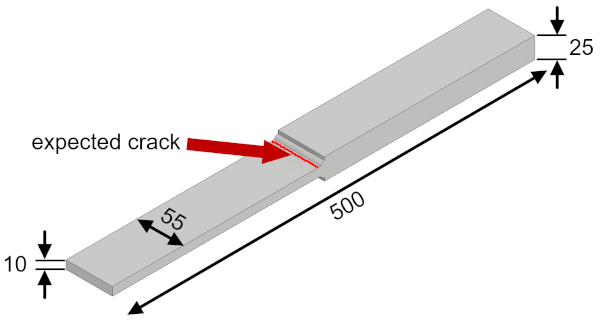
Figure 1: Multilayer K-butt weld specimens used for the fatigue tests. Dimensions in millimeters. Please click here to view a larger version of this figure.
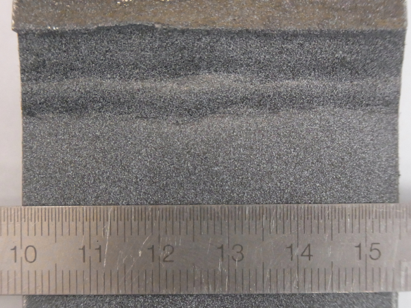
Figure 2: Speckle pattern for digital image correlation at the weld. Please click here to view a larger version of this figure.
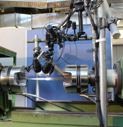
Figure 3: Test setup with DIC cameras and lights supported by a scaffold structure installed above the specimen. Please click here to view a larger version of this figure.
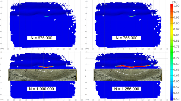
Figure 4: Percent strain in the loading direction (vertical) showing the development of a crack and comparison with beach marks on a specimen in as-welded conditions. N = number of load cycles. Please click here to view a larger version of this figure.
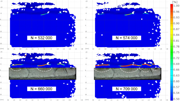
Figure 5: Percent strain in the loading direction (vertical) showing the development of cracks and comparison with beach marks on a stress-relieved specimen. N = number of load cycles. Please click here to view a larger version of this figure.
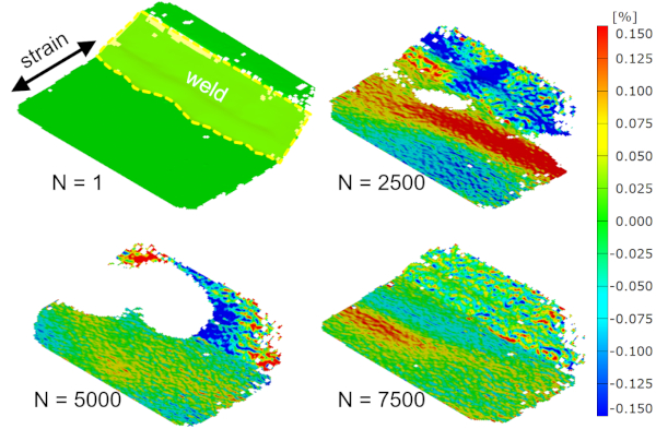
Figure 6: Percent strain in the loading direction at maximum load on the first, static load cycle (N = 1) and at the beginning of the fatigue test at different numbers of load cycles. Please click here to view a larger version of this figure.
Supplemental File 1: Trigger List. Please click here to view this file (Right click to download).
Discussion
The presented procedure consists of using DIC to detect and monitor fatigue cracks on welded specimens tested on a resonance testing machine without interrupting the test. The main challenge in the application is the high load frequency of the resonance testing machine. It requires relatively short exposure times and thus high illumination for the acquisition of the images for the DIC tests. Therefore, lighting has to be maximized. On the other hand, reflections on the metallic surface may require the use of polarization filters, which will reduce the amount of light entering the cameras. To make better use of the light available, the aperture of the objectives may be enlarged. This will reduce the depth of focus. It is therefore necessary to set the focus exactly at the distance of the specimen surface and the out of plane movement of the specimen should not exceed the focused range. The setup of the cameras and lighting requires particular care.
Nevertheless, the strains calculated by DIC might not be very accurate (Figure 6). The computed strains might show high noise. On some of the facets used for DIC, the speckle pattern might not be recognized and strains will not be calculated. But the proposed procedure has proven robust with respect to the quality of the DIC results. Even if the results are not good enough to determine the strains at the weld precisely, it should still be possible to detect cracks.
The butt weld presented here has a relatively smooth weld toe compared to other weld geometries. Cracks are likely to initiate at imperfections along the weld toe with a sharp notch and thus high stress concentration. Unfortunately, it may not be possible to evaluate strains by DIC at these exact locations because the facets used for the computation may not be recognized. For example, Figure 5 shows a crack initiating at the left side of the specimen, missing facets at +25 mm horizontal / -5 mm vertical. But as shown in the example, even if some facets are not evaluated it is still possible to determine when the crack initiates and starts to grow. For welds with a steeper angle and sharper notches (e.g., longitudinal stiffener, fillet weld) it may help to tilt the cameras ~15° to increase the angle to the weld surface. The proposed procedure was applied on longitudinal stiffeners as well. Despite the relatively sharp notch at the weld toe it was possible to reliably detect crack initiation.
Macroscopic cracks are assumed when strains of 1% or more are reached. In a study by Kovárík et al.20, DIC was applied to detect cracks on thermal spray-coated, unnotched specimens. It was stated that the threshold value for crack detection could be set in the range of 0.5% and 1% without significantly affecting the results. These values are confirmed by the comparison with the beach marks (Figure 4 and Figure 5). A lower value will lead to an earlier crack detection but might be more prone to uncertainties and produce less comparable results. A higher value will lead to a later recognition of crack initiation, but the results will probably be more comparable and reproducible.
Applying the first load cycle statically (step 3.3) may result time consuming when many tests are performed. If no plastic strains occur at the weld toe (notch) it might also be omitted and the unloaded condition (step 3.2) used as a reference for strain calculations. Otherwise, one of the images acquired at the beginning of the dynamic test can be used if the image quality is adequate (see Figure 6).
If only a few specimens are tested, the setup time should not be underestimated. It may require some time and iterative loops to install and set up the cameras accurately and perform the calibration to get proper images for the DIC assessment.
Specimen preparation, on the other hand, is quick and inexpensive. Specimens need only be cleaned and sprayed with color to apply the speckle patter. This comes at little cost and makes the proposed DIC-based procedure practical, particularly if a large number of specimens will be tested.
A further benefit, especially for large sets of specimens or tests running overnight, is that the cameras are triggered automatically, and the tests do not need to be interrupted.
A restriction of the DIC procedure is that as an optical method it is limited to surface cracks. Furthermore, it requires that the area to be monitored be visible by the cameras while the specimen is mounted in the testing machine.
The presented procedure was used mainly to detect the start of technical cracks. But as demonstrated, it also allows for the assessment of crack growth (e.g., to determine crack propagation rates). The result will be the length visible on the surface. Crack front curvature cannot be detected, however.
The procedure proved its applicability on welded specimens presenting a relatively complicated surface topology. It should also be applicable to non-welded specimens, as the absence of geometrical notches should facilitate the DIC measurements. A similar procedure has been applied in Kovárík et al.20 on unnotched specimens.
Furthermore, the procedure could also be applied for fatigue tests on servo-hydraulic testing machines. Here, the testing frequency would be lower than on a resonance testing machine. The exposure time of the cameras could thus be longer, which should facilitate the camera setup.
In conclusion, the presented procedure offers a straightforward way to study the development of cracks in fatigue tests. It allows detection of technical cracks and monitoring of crack propagation (e.g., to determine crack propagation rates in fatigue tests). The illustrative nature of the results facilitates their interpretation and assessment. The technique is applicable to resonance testing machines with high loading frequencies without interrupting the tests. The measurements are fully automated, so no continuous supervision is needed. It is applicable on welded specimens presenting a relatively complicated geometry in the region of interest. On small-scale specimens, it allows coverage of the whole width of the specimen. Furthermore, the procedure is characterized by a simple setup and basic post processing, making it a practical alternative to existing methods.
Disclosures
The authors have nothing to disclose.
Acknowledgements
Funded by the Deutsche Forschungsgemeinschaft (DFG, German Research Foundation) EH 485/4-1.
Materials
| Name | Company | Catalog Number | Comments |
| ARAMIS 5M | gom | DIC system including two 5 megapixel cameras and control unit | |
| ARAMIS | gom | v6.3.1-2 | DIC software |
| Calibration object | gom | CP 20 | MV 30 x 24 mm2 |
| Camera objectives, 50 mm | Titanar 2.8 / 50 | ||
| Hydraulic Wedge Grip | MTS | 647.25A02 | |
| Hydraulic Grip Supply | MTS | 685.10 | 10,000 Psi |
| LED lights | Diana LEDscale | KSP0495-0001A | 4 x 16 W LED lights |
| Polarization filters | Schneider-Kreuznach | 52,0 AUF (2 x for cameras) | |
| Polarization filters | Schneider-Kreuznach | 67,0 AUF (4 x for lights) | |
| Resonance testing machine | Schenck | 200 kN resonance testing machine | |
| Resonance testing machine control unit | Rumul | v 2.5.3 | Resonance testing machine control unit and software |
| Spray paint | Black and white spray paint, matt |
References
- Belloni, V., et al. Digital image correlation from commercial to FOS software: a mature technique for full-field displacement measurements. The International Archives of the Photogrammetry, Remote Sensing and Spatial Information Sciences. XLII-2, 91-95 (2018).
- Shrama, K., Clarke, A., Pullin, R., Evans, S. L. Detection of cracking in mild steel fatigue specimens using acoustic emission and digital image correlation. 31st Conference of the European Working Group on Acoustic Emission. , Dresden, Germany. (2014).
- Carroll, J. D., Abuzaid, W., Lambros, J., Sehitoglu, H. High resolution digital image correlation measurements of strain accumulation in fatigue crack growth. International Journal of Fatigue. 57, 140-150 (2013).
- Malitckii, E., Remes, H., Lehto, P., Bossuyt, S. Full-field strain measurements for microstructurally small fatigue crack propagation using digital image correlation method. Journal of Visualized Experiments. (143), e59134(2019).
- Rabbolini, S., Beretta, S., Foletti, S., Cristea, M. E. Crack closure effects during low cycle fatigue propagation in line pipe steel: An analysis with digital image correlation. Engineering Fracture Mechanics. 148, 441-456 (2015).
- Carroll, J. D., et al. Multiscale analysis of fatigue crack growth using digital image correlation. Proceedings of the XIth International Congress and Exposition on Experimental and Applied Mechanics. , Orlando, FL. (2008).
- Durif, E., Fregonese, M., Rethore, J., Combescure, A. Development of a digital image correlation controlled fatigue crack propagation experiment. EPJ Web of Conferences. 6, 31012(2010).
- Maletta, C., Bruno, L., Corigliano, P., Crupi, V., Guglielmino, E. Crack-tip thermal and mechanical hysteresis in Shape Memory Alloys under fatigue loading. Materials Science & Engineering A. 616, 281-287 (2014).
- Rupil, J., Roux, S., Hild, F., Vincent, L. Fatigue microcrack detection with digital image correlation. The Journal of Strain Analysis for Engineering Design. 46 (6), 492-509 (2011).
- Risbet, M., Feissel, P., Roland, T., Brancherie, D., Roelandt, J. M. Digital image correlation technique: application to early fatigue damage detection in stainless steel. Procedia Engineering. 2, 2219-2227 (2010).
- Tavares, P. J., Ramos, T., Braga, D., Vaz, M. A. P., Moreira, P. M. G. P. SIF determination with digital image correlation. International Journal of Structural Integrity. 6 (6), 668-676 (2015).
- Hasheminejad, N., et al. Digital image correlation to investigate crack propagation and healing of asphalt concrete. Proceedings of the 18th International Conference on Experimental Mechanics. , Brussels, Belgium. (2018).
- Poncelet, M., et al. Biaxial high cycle fatigue of a type 304L stainless steel: cyclic strains and crack initiation detection by digital image correlation. European Journal of Mechanics / A Solids. 29 (5), 810-825 (2010).
- Corigliano, P., et al. Fatigue assessment of Ti-6Al-4V titanium alloy laser welded joints in absence of filler material by means of full-field techniques. Frattura ed Integrità Strutturale. 43, 171-181 (2018).
- Corigliano, P., Crupi, V., Guglielmino, E., Sili, A. M. Full-field analysis of AL/FE explosive welded joints for shipbuilding applications. Marine Structures. 57, 207-218 (2018).
- Koster, M., Kenel, C., Lee, W., Leinenbach, C. Digital image correlation for the characterization of fatigue damage evolution in brazed steel joints. Procedia Materials Science. 3, 1117-1122 (2014).
- Vanlanduit, S., Vanherzeele, J., Longo, R., Guillaume, P. A digital image correlation method for fatigue test experiments. Optics and Lasers in Engineering. 47, 371-378 (2009).
- Lorenzino, P., Beretta, G., Navarro, A. Application of Digital Image Correlation (DIC) in resonance machines for measuring fatigue crack growth. Frattura ed Integrità Strutturale. 30, 369-374 (2014).
- Kovárík, O., et al. Resonance bending fatigue testing with simultaneous damping measurement and its application on layered coatings. International Journal of Fatigue. 82, 300-309 (2016).
- Kovárík, O., et al. Fatigue crack growth in bodies with thermally sprayed coating. Journal of Thermal Spray Technology. 25 (1-2), 311-320 (2016).
- Friedrich, N., Ehlers, S. A simplified welding simulation approach used to design a fatigue test specimen containing residual stresses. Ship Technology Research. 66 (1), 22-37 (2019).
- Full-field measurements and identification in solid mechanics. Grédiac, M., Hild, F. , ISTE and Wiley. London, UK; Hoboken, NJ. (2013).
Reprints and Permissions
Request permission to reuse the text or figures of this JoVE article
Request PermissionThis article has been published
Video Coming Soon
Copyright © 2025 MyJoVE Corporation. All rights reserved