Method Article
Combining Augmented Reality and 3D Printing to Display Patient Models on a Smartphone
In This Article
Summary
Presented here is a method to design an augmented reality smartphone application for the visualization of anatomical three-dimensional models of patients using a 3D-printed reference marker.
Abstract
Augmented reality (AR) has great potential in education, training, and surgical guidance in the medical field. Its combination with three-dimensional (3D) printing (3DP) opens new possibilities in clinical applications. Although these technologies have grown exponentially in recent years, their adoption by physicians is still limited, since they require extensive knowledge of engineering and software development. Therefore, the purpose of this protocol is to describe a step-by-step methodology enabling inexperienced users to create a smartphone app, which combines AR and 3DP for the visualization of anatomical 3D models of patients with a 3D-printed reference marker. The protocol describes how to create 3D virtual models of a patient’s anatomy derived from 3D medical images. It then explains how to perform positioning of the 3D models with respect to marker references. Also provided are instructions for how to 3D print the required tools and models. Finally, steps to deploy the app are provided. The protocol is based on free and multi-platform software and can be applied to any medical imaging modality or patient. An alternative approach is described to provide automatic registration between a 3D-printed model created from a patient’s anatomy and the projected holograms. As an example, a clinical case of a patient suffering from distal leg sarcoma is provided to illustrate the methodology. It is expected that this protocol will accelerate the adoption of AR and 3DP technologies by medical professionals.
Introduction
AR and 3DP are technologies that provide increasing numbers of applications in the medical field. In the case of AR, its interaction with virtual 3D models and the real environment benefits physicians in regards to education and training1,2,3, communication and interactions with other physicians4, and guidance during clinical interventions5,6,7,8,9,10. Likewise, 3DP has become a powerful solution for physicians when developing patient-specific customizable tools11,12,13 or creating 3D models of a patient’s anatomy, which can help improve preoperative planning and clinical interventions14,15.
Both AR and 3DP technologies help to improve orientation, guidance, and spatial skills in medical procedures; thus, their combination is the next logical step. Previous work has demonstrated that their joint use can increase value in patient education16, facilitating explanations of medical conditions and proposed treatment, optimizing surgical workflow17,18 and improving patient-to-model registration19. Although these technologies have grown exponentially in recent years, their adoption by physicians is still limited, since they require extensive knowledge of engineering and software development. Therefore, the purpose of this work is to describe a step-by-step methodology that enables the use of AR and 3DP by inexperienced users without the need for broad technical knowledge.
This protocol describes how to develop an AR smartphone app that allows the superimposing of any patient-based 3D model onto a real-world environment using a 3D-printed marker tracked by the smartphone camera. In addition, an alternative approach is described to provide automatic registration between a 3D-printed biomodel (i.e., a 3D model created from a patient’s anatomy) and the projected holograms. The protocol described is entirely based on free and multi-platform software.
In previous work, AR patient-to-image registration has been calculated manually5 with surface recognition algorithms10 or has been unavailable2. These methods have been considered somewhat limited when an accurate registration is required19. To overcome these limitations, this work provides tools to perform accurate and simple patient-to-image registration in AR procedures by combining AR technology and 3DP.
The protocol is generic and can be applied to any medical imaging modality or patient. As an example, a real clinical case of a patient suffering from distal leg sarcoma is provided to illustrate the methodology. The first step describes how to easily segment the affected anatomy from computed tomography (CT) medical images to generate 3D virtual models. Afterward, positioning of the 3D models is performed, then the required tools and models are 3D-printed. Finally, the desired AR app is deployed. This app allows for the visualization of patient 3D models overlaid on a smartphone camera in real-time.
Protocol
This study was performed in accordance with the principles of the 1964 Declaration of Helsinki as revised in 2013. The anonymized patient data and pictures included in this paper are used after written informed consent was obtained from the participant and/or their legal representative, in which he/she approved the use of this data for dissemination activities including scientific publications.
1. Workstation Set-up for Segmentation, 3D Models Extraction, Positioning, and AR App Deployment
NOTE: This protocol has been tested with the specific software version indicated for each tool. It is likely to work with newer versions, although it is not guaranteed.
- Use a computer with Microsoft Windows 10 or Mac OS as operating systems.
- Install the following tools from the corresponding websites per the official instructions:
3D Slicer (v. 4.10.2): https://download.slicer.org/.
Meshmixer (v. 3.5): http://www.meshmixer.com/download.html.
Unity (v. 2019): https://unity3d.com/get-unity/download.
(For iOS deployment only) Xcode (last version): https://developer.apple.com/xcode/.
NOTE: All software tools required for completing the protocol can be freely downloaded for personal purposes. Software to be used in each step will be specifically indicated. - Download data from the following GitHub repository, found at https://github.com/BIIG-UC3M/OpenARHealth.
NOTE: The repository contains the following folders:
"/3DSlicerModule/": 3D slicer module for positioning 3D models with respect to the 3D-printed marker. Used in section 3. Add the module into the 3D slicer following the instructions available at https://github.com/BIIG-UC3M/OpenARHealth.
"/Data/PatientData/Patient000_CT.nrrd": CT of a patient suffering from distal leg sarcoma. The protocol is described using this image as an example.
"/Data/Biomodels/": 3D models of the patient (bone and tumor).
"/Data/Markers/": Markers that will be 3D-printed, which will be detected by the AR application to position the virtual 3D models. There are two markers available.
2. Biomodel Creation
NOTE: The goal of this section is to create 3D models of the patient's anatomy. They will be obtained by applying segmentation methods to a medical image (here, using a CT image). The process consists of three different steps: 1) loading the patient data into 3D slicer software, 2), segmentation of target anatomy volumes, and 3) exportation of segmentation as 3D models in OBJ format. The resulting 3D models will be visualized in the final AR application.
- Load patient data ("/Data/PatientData/Patient000_CT.nrrd") by dragging the medical image file into the 3D slicer software window. Click OK. The CT views (axial, sagittal, coronal) will appear on the corresponding windows.
NOTE: The data used here is found in "nearly raw raster data" (NRRD) format, but 3D Slicer allows for loading of medical image format (DICOM) files. Go to the following link for further instructions, found at https://www.slicer.org/wiki/Documentation/4.10/Training. - To segment the anatomy of the patient, go to the Segment Editor module in 3D slicer.
- A "segmentation" item is created automatically when entering the module. Select the desired volume (a medical image of the patient) in the Master Volume section. Then, right-click below on the Add button to create a segment. A new segment will be created with the name "Segment_1".
- There is a panel called Effects that contains a variety of tools to properly segment the target area of the medical image. Select the most convenient tool for the target and segment onto the image windows area.
- To segment the bone (tibia and fibula in this case), use the Threshold tool to set up minimum and maximum HU values from the CT image, which corresponds to bone tissue. By using this tool, other elements with HU outside these threshold values are removed, such as soft tissue.
- Use the Scissors tool to remove undesired areas, such as the bed or other anatomical structures, from the segmented mask. Segment the sarcoma manually using the Draw and Erase tools, since the tumor is difficult to contour with automatic tools.
NOTE: To learn more details about the segmentation procedure, go to the link found at https://www.slicer.org/wiki/Documentation/4.10/Training#Segmentation.
- Click on the Show 3D button to view a 3D representation of the segmentation.
- Export the segmentation in a 3D model file format by going to the Segmentations module in 3D Slicer.
- Go to Export/import models and labelmaps. Select Export in the operation section and Models in the output type section. Click Export to finish and create the 3D model from the segmented area.
- Select SAVE (upper left) to save the model. Choose the elements to be saved. Then, change the file format of the 3D Model to "OBJ" within the File format column. Select the path where files will be stored and click on Save.
- Repeat steps 2.2 and 2.3 to create additional 3D models of different anatomical regions.
NOTE: Pre-segmented models of the provided example can be found in the data previously downloaded in step 1.3 ("/Data/Biomodels/").
3. Biomodel Positioning
NOTE: In this section, the 3D models created in Section 2 will be positioned with respect to the marker for augmented reality visualization. The ARHealth: Model Position module from 3D Slicer will be used for this task. Follow the instructions provided in step 1.3 to add the module to 3D Slicer. There are two different alternatives to position the 3D models: "Visualization" mode and "Registration" mode.
- Visualization mode
NOTE: Visualization mode allows positioning of the 3D patient models at any position with respect to the AR marker. With this option, the user is able to use the AR app to visualize biomodels using the 3D-printed AR marker as a reference. This mode may be used when precision is not required, and visualization of the virtual model can be displayed anywhere within the field-of-view of the smartphone camera and marker.- Go to the ARHealth: Model Position module, and (in the initialization section) select Visualization mode. Click on Load Marker Model to load the marker for this option.
- Load the 3D models created in section 2 by clicking on the … button to select the path of the saved models from section 2. Then, click on the Load Model button to load it in 3D Slicer. Models must be loaded one at a time. To delete any models previously loaded, click on that model followed by the Remove Model button, or click Remove All to delete all models loaded at once.
- Click the Finish and Center button to center all models within the marker.
- The position, orientation, and scaling of the 3D models can be modified with respect to the marker with different slider bars (i.e., translation, rotation, scale).
NOTE: There is an additional "Reset Position" button to reset the original position of the models before making any changes in the position. - Save the models at this position by choosing the path to store the files and clicking the Save Models button. The 3D models will be saved with the extension name "_registered.obj".
- Registration mode
NOTE: Registration mode allows combining of the AR marker with one 3D biomodel at any desired position. Then, any section of the combined 3D models (that includes the AR marker) can be extracted and 3D-printed. All biomodels will be displayed in the AR app using this combined 3D-printed biomodel as a reference. This mode allows the user to easily register the patient (here, a section of the patient's bone) and virtual models using a reference marker.- Go to the ARHealth: Model Position module, and (in the initialization section) select Registration mode. Click on Load Marker Model to load the marker for this option.
- Load the models as done in step 3.1.2.
- Move the 3D models and ensure their intersection with the supporting structure of the cube marker, since these models will be combined and 3D-printed later. The height of the marker base can be modified. The position, orientation, and scaling of the 3D models can be modified with respect to the marker with different slider bars (i.e., translation, rotation, scale).
- Save the models at this position by choosing the path to store the files and clicking the Save Models button. The 3D models will be saved with the extension name "_registered.obj".
- The anatomy model may be too large. If so, cut the 3D model around the marker adaptor and 3D-print only a section of the combination of both models using Meshmixer software.
- Open Meshmixer and load the biomodel and supporting structure of the cube marker model saved in step 3.2.4. Combine these models by selecting both models in the Object Browser window. Click on the Combine option in the tool window that has just appeared in the upper left corner.
- In Meshmixer, use the Plane Cut tool under the Edit menu to remove unwanted sections of the model that will not be 3D-printed.
- To save the model to be 3D-printed, go to File > Export and select the desired format.
4. 3D Printing
NOTE: The aim of this step is to 3D-print the physical models required for the final AR application. The marker to be detected by the application and the different objects needed depend on the mode selected in section 3. Any material can be used for 3D printing for the purpose of this work, when following the color material requirements requested at each step. Polylactic acid (PLA) or acrylonitrile butadiene styrene (ABS) are both sufficient choices.
- Use a 3D printer to print the cubic marker. If a dual extruder 3D printer is not available, skip to step 4.2. Use a dual extruder 3D printer specifically to print the two-color marker provided in "Data/Markers/Marker1_TwoColorCubeMarker/". In the 3D printing software, select a white color material for the file "TwoColorCubeMarker_WHITE.obj" and black color material for "TwoColorCubeMarker_BLACK.obj".
NOTE: For better marker detection, print on high-quality mode with a small layer height. - If a dual extruder 3D printer is not available and step 4.1 was not performed, follow this step to print a 3D-printed marker with stickers as an alternative by doing the following:
- Use a 3D printer to print the file "Data/Markers/ Marker2_StickerCubeMarker/ StickerCubeMarker_WHITE.obj" with white color material.
- Use a conventional printer to print the file "Data/Markers/ Marker2_StickerCubeMarker/Stickers.pdf" on sticker paper. Then, use any cutting tool to precisely cut the images though the black frame by removing the black lines.
NOTE: It is recommended to use sticker paper to obtain a higher quality marker. However, the images can be printed on regular paper, and a common glue stick can be used to paste the images on the cube. - Place stickers in the 3D-printed cube obtained in step 4.2.1 in the corresponding order following instructions from the document "Data/Markers/ Marker2_StickerCubeMarker/Stickers.pdf".
NOTE: Stickers are smaller than the face of the cube. Leave a 1.5 mm frame between the sticker and edge of the face. "Data/Markers/Marker2_StickerCubeMarker/StickerPlacer.stl" can be 3D-printed to guide the sticker positioning and exactly match the center of the cube face.
- 3D-print the adaptors, depending on the mode selected in section 3.
- If Visualization mode (section 3.1), was selected, 3D-print "Data/3DPrinting/Option1/ MarkerBaseTable.obj", which is a base adaptor used to place the marker in vertical position on a horizontal surface.
- If Registration mode (section 3.2) was selected, 3D-print the model created in step 3.2.8 with the marker adaptor attached.
NOTE: 3D printed objects from step 4.3 can be printed in any color material.
5. AR App Deployment
NOTE: The goal of this section is to design a smartphone app in Unity engine that includes the 3D models created in the previous sections and deploy this app on a smartphone. A Vuforia Development License Key (free for personal use) is required for this step. The app can be deployed on Android or iOS devices.
- Create a Vuforia Developer account to obtain a license key to use their libraries in Unity. Go to the link found at https://developer.vuforia.com/vui/auth/register and create an account.
- Go to the link found at https://developer.vuforia.com/vui/develop/Licenses and select Get Development Key. Then, follow the instructions to add a free development license key into the user's account.
- In the License Manager menu, select the key created in the previous step and copy the provided key, which will be used in step 5.3.3.
- Set up the smartphone.
- To get started with Unity and Android devices, go to the link found at https://docs.unity3d.com/Manual/android-GettingStarted.html.
- To get started with Unity and iOS devices, go to the link found at https://docs.unity3d.com/Manual/iphone-GettingStarted.html.
- Set up a Unity Project for the AR app by first opening Unity v.2019 and creating a new 3D project. Then, under Build Settings in the File menu, switch the platform to either an Android or iOS device.
- Enable Vuforia into the project by selecting Edit > Project Setting > Player Settings > XR Settings and checking the box labeled Vuforia Augmented Reality Support.
- Create an "ARCamera" under Menubar > GameObject > Vuforia Engine > ARCamera and import Vuforia components when prompted.
- Add the Vuforia License Key into Vuforia Configuration settings by selecting the Resources folder and clicking on Vuforia Configuration. Then, in the App License Key section, paste the key copied in section 5.1.2.
- Import the Vuforia Target file provided in "/Data/Vuforia/ AR_Cube_3x3x3.unitypackage" into Unity, which contains the files that Vuforia requires to detect the markers described in section 4.
- Create a Vuforia MultiTarget under Menubar > GameObject > Vuforia Engine > Multi Image.
- Select the marker type that will be used for detection by clicking on the MultiTarget created in the previous step. In the Database option under Multi Target Behaviour, select ARHealth_3DPrintedCube_30x30x30. In the Multi Target option under Multi Target Behaviour, select either TwoColorCubeMarker or StickerCubeMarker, depending on the marker created in section 4.
- Load the 3D models created in section 3 into Unity Scene under MultiTarget by creating a new folder with the name "Models" under the "Resources" folder. Drag the 3D models into this folder. Once loaded in Unity, drag them under the "MultiTarget" item created in step 5.3.5. This will make them dependent on the marker.
NOTE: Models should be visible in the Unity 3D view scene. - Change the colors of the 3D models by creating a new material and assigning the new materials to the models.
- Create a new folder named "Materials" under the "Resources" folder by going to Menubar > Assets > Create > Material. Select the material and change the color in the configuration section. Then, drag the file under the 3D model hierarchy.
- Optional: if there is a webcam available, click on the play button located in the upper-middle portion to test its application on the computer. If the marker is visible to the webcam, it should be detected, and the 3D models should appear in the scene.
- If an Android smartphone is used for app deployment, go to File > Build Settings in Unity, and select the plugged phone from the list. Select Deploy and Run. Save the file with extension .apk on the computer and allow the process to finish. Once deployment is done, the app should be on the phone and ready to run.
NOTE: This protocol has been tested on Android v.8.0 Oreo or above. Correct functionality is not guaranteed for older versions. - If the app will be deployed in an iOS device, go to File > Build Settings in Unity and select Run. Select the path to save the app files. Allow the process to finish. Go to the saved folder and open the file with the extension ".projectxcode".
- In Xcode, follow the instructions from step 5.2.2 to complete deployment.
NOTE: For more information about Vuforia in Unity, go to the link found at https://library.vuforia.com/articles/Training/getting-started-with-vuforia-in-unity.html.
- In Xcode, follow the instructions from step 5.2.2 to complete deployment.
6. App Visualization
- Open the installed app, which will use the smartphone's camera. When running the app, look at the marker with the camera from a short distance away (40 cm minimum). Once the app detects the marker, the 3D models created in previous steps should appear exactly at the location defined during the procedure on the smartphone screen.
NOTE: Illumination can alter the precision of marker detection. It is recommended to use the app in environments with good lighting conditions.
Results
The protocol was applied to data from a patient suffering from distal leg sarcoma in order to visualize the affected anatomical region from a 3D perspective. Using the method described in section 2, the portion of the affected bone (here, the tibia and fibula) and tumor were segmented from the patient's CT scan. Then, using the segmentation tools from 3D Slicer, two biomodels were created: the bone (section of the tibia and fibula) (Figure 1A) and tumor (Figure 1B).
Next, the two 3D models were positioned virtually with respect to the marker for optimal visualization. Both modes described in section 3 were followed for this example. For visualization mode, the models were centered in the upper face of the marker (Figure 2). For registration mode, the marker adaptor was positioned in the bone (specifically, the tibia [Figure 3]). Then, a small section of the tibia was selected to be 3D-printed with a 3D marker adaptor (Figure 4). An Ultimaker 3 extended 3D printer with PLA material was used to create the 3D-printed markers (Figure 5A, B), marker holder base (Figure 5C) for the "visualization" mode, and section of the tibia for "registration" mode (Figure 5D). Figure 5E shows how the marker was attached to the "visualization" mode 3D-printed base. Figure 5F shows the attachment with the "registration" mode 3D-printed biomodel. Finally, Unity was used to create the app and deploy it on the smartphone.
Figure 6 shows how the app worked for "visualization" mode. The hologram was accurately located in the upper part of the cube as previously defined. Figure 7 shows the application for "registration" mode, in which the app positioned the complete bone model on top of the 3D-printed section. The final visualization of the holograms was clear and realistic, maintained the real sizes of the biomodels, and positioned accurately. When using the smartphone application, the AR marker needs to be visible by the camera for the app to correctly display the holograms. In addition, the light conditions in the scene must be of good quality and constant for proper marker detection. Bad light conditions or reflections on the marker surface hinder the tracking of the AR marker and cause malfunctioning of the app.
The time required to create the app depends on several factors. The duration of section 1 is limited by the download speed. Regarding anatomy segmentation (section 2), factors affecting segmentation time include complexity of the region and medical imaging modality (i.e., CT is easily segmented, while MRI is more difficult). For the representative example of the tibia, approximately 10 min was required to generate both 3D models from the CT scan. Biomodel positioning (section 3) is simple and straightforward. Here, it took approximately 5 min to define the biomodel position with respect to the AR marker. For the 3D printing step, the duration is highly dependent on the selected mode. The "dual color marker" was manufactured at high quality in a period of 5 h and 20 min. The "sticker marker" was manufactured in a period of 1 h and 30 min, plus the time required to paste the stickers. The final step for app development can be time-consuming for those with no previous experience in Unity, but it can be easily completed following the protocol steps. Once the AR markers have been 3D-printed, the development of an entirely new AR app can be performed in less than 1 h. This duration can be further reduced with additional experience.
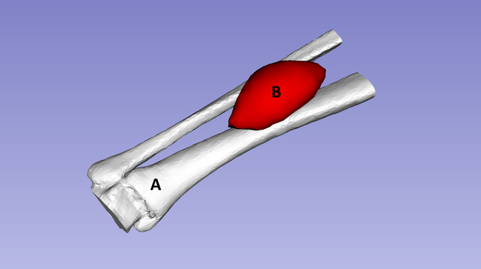
Figure 1: Representation of 3D models created from a CT image of a patient suffering from distal leg sarcoma. (A) Bone tissue represented in white (tibia and fibula). (B) Tumor represented in red. Please click here to view a larger version of this figure.
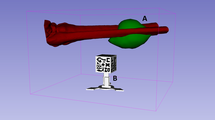
Figure 2: Results showing how "visualization" mode in 3D Slicer positions the virtual 3D models of the bone and tumor with respect to 3D-printed marker reference. The patient 3D models (A) are positioned above the upper face of the marker cube (B). Please click here to view a larger version of this figure.
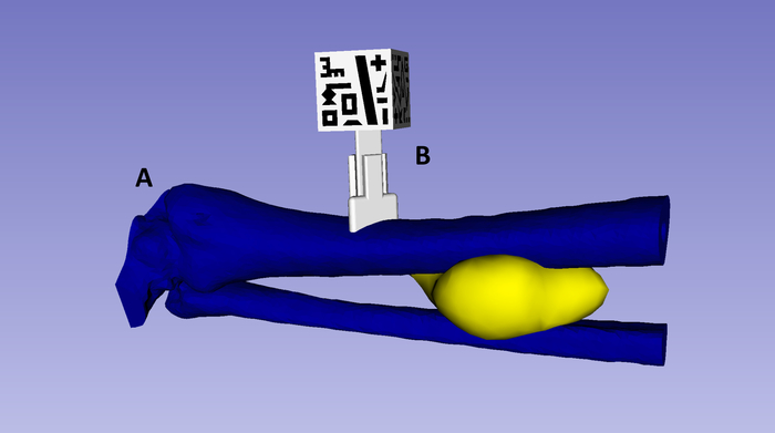
Figure 3: Results showing how "registration" mode in 3D Slicer positions the virtual 3D models of the bone and tumor (A) with respect to 3D-printed marker reference (B). The marker adaptor is attached to the bone tissue model. Please click here to view a larger version of this figure.
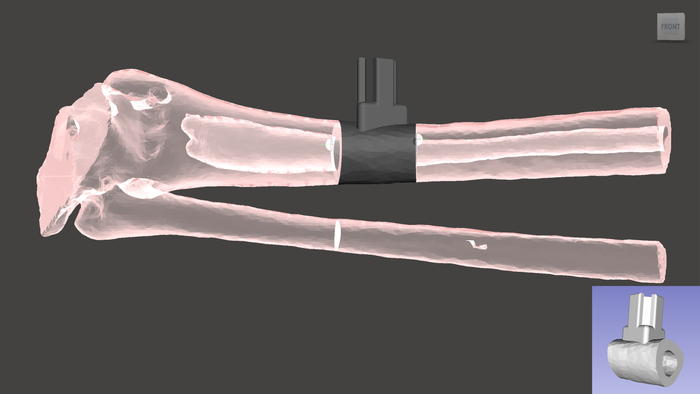
Figure 4: Small section of the bone tissue and 3D marker adaptor. The two components are combined then 3D-printed. Please click here to view a larger version of this figure.
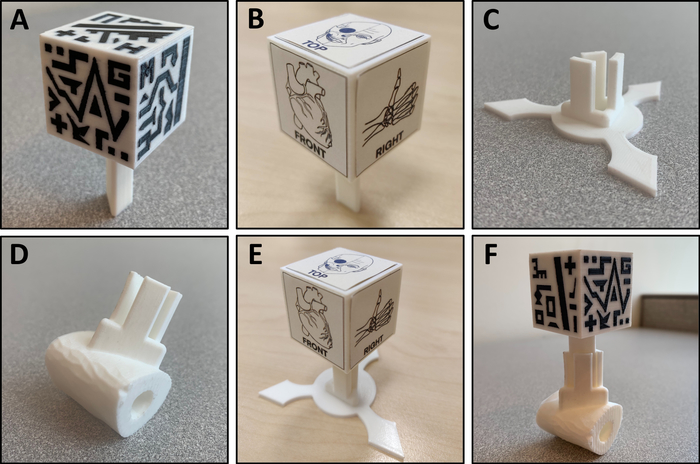
Figure 5: 3D printed tools required for the final application. (A) "Two color cube marker" 3D-printed with two colors of materials. (B) "Sticker cube marker" 3D-printed, with stickers pasted. (C) Marker base cube adaptor. (D) Section of the patient's bone tissue 3D model and marker cube adaptor. (E) "Sticker cube marker" placed in the marker base cube adaptor. (F) "Two color cube marker" placed in the marker adaptor attached to the patient's anatomy. Please click here to view a larger version of this figure.
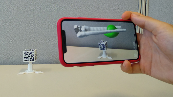
Figure 6: App display when using "visualization" mode. The patient's affected anatomy 3D models are positioned above the upper face of the 3D-printed cube. Please click here to view a larger version of this figure.
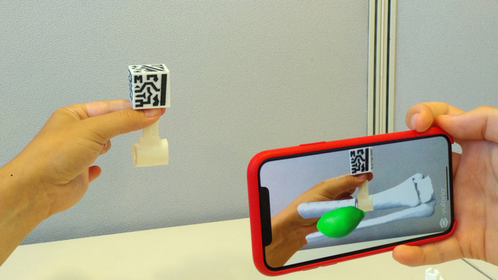
Figure 7: AR visualization when using "registration" mode. The 3D-printed marker enables registration of the 3D-printed biomodel with the virtual 3D models. Please click here to view a larger version of this figure.
Discussion
AR holds great potential in education, training, and surgical guidance in the medical field. Its combination with 3D printing opens may open new possibilities in clinical applications. This protocol describes a methodology that enables inexperienced users to create a smartphone app combining AR and 3DP for the visualization of anatomical 3D models of patients with 3D-printed reference markers.
In general, one of the most interesting clinical applications of AR and 3DP is to improve patient-to-physician communication by giving the patient a different perspective of the case, improving explanations of specific medical conditions or treatments. Another possible application includes surgical guidance for target localization, in which 3D-printed patient-specific tools (with a reference AR marker attached) can be placed on rigid structures (i.e., bone) and used as a reference for navigation. This application is especially useful for orthopedic and maxillofacial surgical procedures, in which bone tissue surface is easily accessed during surgery.
The protocol starts with section 1, describing the workstation set-up and software tools necessary. Section 2 describes how to use 3D Slicer software to easily segment target anatomies of the patient from any medical imaging modality to obtain 3D models. This step is crucial, as the virtual 3D models created are those displayed in the final AR application.
In section 3, 3D Slicer is used to register the 3D models created in the previous section with an AR marker. During this registration procedure, patient 3D models are efficiently and simply positioned with respect to the AR marker. The position defined in this section will determine the hologram relative position in the final app. It is believed that this solution reduces complexity and multiplies the possible applications. Section 3 describes two different options to define the spatial relationships between the models and AR markers: "visualization" and "registration" mode. The first option, "visualization" mode, allows the 3D models to be positioned anywhere with respect to the marker and displayed as the whole biomodel. This mode provides a realistic, 3D perspective of the patient's anatomy and allows moving and rotating of the biomodels by moving the tracked AR marker. The second option, "registration" mode, allows attachment and combining of a marker adaptor to any part of the biomodel, offering an automatic registration process. With this option, a small section of the 3D model, including the marker adaptor, can be 3D-printed, and the app can display the rest of the model as a hologram.
Section 4 provides guidelines for the 3D printing process. First, the user can choose between two different markers: the "dual color marker" and "sticker marker". The whole "dual color marker" can be 3D-printed but requires a dual extruder 3D printer. In case this printer is not available, the "sticker marker" is proposed. This is a simpler marker that can be obtained by 3D-printing the cubic structure, then pasting the images of the cube with sticker paper or sticker glue. Furthermore, both markers were designed with extensible sections to perfectly fit in a specific adaptor. Thus, the marker can be reused in several cases.
Section 5 describes the process to create a Unity project for AR using the Vuforia software development kit. This step may be the hardest portion for users with no programming experience, but with these guidelines, it should be easier to obtain the final application that is presented in section 6. The app displays the patient's virtual models over the smartphone screen when the camera recognizes the 3D-printed marker. In order for the app to detect the 3D marker, a minimum distance of approximately 40 cm or less from the phone to the marker as well as good lighting conditions are required.
The final application of this protocol allows the user to choose the specific biomodels to visualize and in which positions. Addtionally, the app can perform automatic patient-hologram registration using a 3D-printed marker and adaptor attached to the biomodel. This solves the challenge of registering virtual models with the environment in a direct and convenient manner. Moreover, this methodology does not require broad knowledge of medical imaging or software development, does not depend on complex hardware and expensive software, and can be implemented over a short time period. It is expected that this method will help accelerate the adoption of AR and 3DP technologies by medical professionals.
Disclosures
The authors have nothing to disclose.
Acknowledgements
This report was supported by projects PI18/01625 and PI15/02121 (Ministerio de Ciencia, Innovación y Universidades, Instituto de Salud Carlos III and European Regional Development Fund "Una manera de hacer Europa") and IND2018/TIC-9753 (Comunidad de Madrid).
Materials
| Name | Company | Catalog Number | Comments |
| 3D Printing material: Acrylonitrile Butadiene Styrene (ABS) | Thermoplastic polymer material usually used in domestic 3D printers. | ||
| 3D Printing material: Polylactic Acid (PLA) | Bioplastic material usually used in domestic 3D printers. | ||
| 3D Slicer | Open-source software platform for medical image informatics, image processing, and three-dimensional visualization | ||
| Android | Alphabet, Inc. | Android is a mobile operating system developed by Google. It is based on a modified version of the Linux kernel and other open source software, and is designed primarily for touchscreen mobile devices such as smartphones and tablets. | |
| Autodesk Meshmixer | Autodesk, Inc. | Meshmixer is state-of-the-art software for working with triangle meshes. Free software. | |
| iPhone OS | Apple, Inc. | iPhone OS is a mobile operating system created and developed by Apple Inc. exclusively for its hardware. | |
| Ultimaker 3 Extended | Ultimaker BV | Fused deposition modeling 3D printer. | |
| Unity | Unity Technologies | Unity is a real-time development platform to create 3D, 2D VR & AR visualizations for Games, Auto, Transportation, Film, Animation, Architecture, Engineering & more. Free software. | |
| Xcode | Apple, Inc. | Xcode is a complete developer toolset for creating apps for Mac, iPhone, iPad, Apple Watch, and Apple TV. Free software. |
References
- Coles, T. R., John, N. W., Gould, D., Caldwell, D. G. Integrating Haptics with Augmented Reality in a Femoral Palpation and Needle Insertion Training Simulation. IEEE Transactions on Haptics. 4 (3), 199-209 (2011).
- Pelargos, P. E., et al. Utilizing virtual and augmented reality for educational and clinical enhancements in neurosurgery. Journal of Clinical Neuroscience. 35, 1-4 (2017).
- Abhari, K., et al. Training for Planning Tumour Resection: Augmented Reality and Human Factors. IEEE Transactions on Biomedical Engineering. 62 (6), 1466-1477 (2015).
- Uppot, R., et al. Implementing Virtual and Augmented Reality Tools for Radiology Education and Training, Communication, and Clinical Care. Radiology. 291, 182210 (2019).
- Pratt, P., et al. Through the HoloLensTM looking glass: augmented reality for extremity reconstruction surgery using 3D vascular models with perforating vessels. European Radiology Experimental. 2 (1), 2 (2018).
- Rose, A. S., Kim, H., Fuchs, H., Frahm, J. -. M. Development of augmented-reality applications in otolaryngology-head and neck surgery. The Laryngoscope. , (2019).
- Zhou, C., et al. Robot-Assisted Surgery for Mandibular Angle Split Osteotomy Using Augmented Reality: Preliminary Results on Clinical Animal Experiment. Aesthetic Plastic Surgery. 41 (5), 1228-1236 (2017).
- Heinrich, F., Joeres, F., Lawonn, K., Hansen, C. Comparison of Projective Augmented Reality Concepts to Support Medical Needle Insertion. IEEE Transactions on Visualization and Computer Graphics. 25 (6), 1 (2019).
- Deng, W., Li, F., Wang, M., Song, Z. Easy-to-Use Augmented Reality Neuronavigation Using a Wireless Tablet PC. Stereotactic and Functional Neurosurgery. 92 (1), 17-24 (2014).
- Fan, Z., Weng, Y., Chen, G., Liao, H. 3D interactive surgical visualization system using mobile spatial information acquisition and autostereoscopic display. Journal of Biomedical Informatics. 71, 154-164 (2017).
- Arnal-Burró, J., Pérez-Mañanes, R., Gallo-del-Valle, E., Igualada-Blazquez, C., Cuervas-Mons, M., Vaquero-Martín, J. Three dimensional-printed patient-specific cutting guides for femoral varization osteotomy: Do it yourself. The Knee. 24 (6), 1359-1368 (2017).
- Vaquero, J., Arnal, J., Perez-Mañanes, R., Calvo-Haro, J., Chana, F. 3D patient-specific surgical printing cutting blocks guides and spacers for open- wedge high tibial osteotomy (HTO) - do it yourself. Revue de Chirurgie Orthopédique et Traumatologique. 102, 131 (2016).
- De La Peña, A., De La Peña-Brambila, J., Pérez-De La Torre, J., Ochoa, M., Gallardo, G. Low-cost customized cranioplasty using a 3D digital printing model: a case report. 3D Printing in Medicine. 4 (1), 1-9 (2018).
- Kamio, T., et al. Utilizing a low-cost desktop 3D printer to develop a "one-stop 3D printing lab" for oral and maxillofacial surgery and dentistry fields. 3D Printing in Medicine. 4 (1), 1-7 (2018).
- Punyaratabandhu, T., Liacouras, P., Pairojboriboon, S. Using 3D models in orthopedic oncology: presenting personalized advantages in surgical planning and intraoperative outcomes. 3D Printing in Medicine. 4 (1), 1-13 (2018).
- Wake, N., et al. Patient-specific 3D printed and augmented reality kidney and prostate cancer models: impact on patient education. 3D Printing in Medicine. 5 (1), 1-8 (2019).
- Barber, S. R., et al. Augmented Reality, Surgical Navigation, and 3D Printing for Transcanal Endoscopic Approach to the Petrous Apex. OTO Open: The Official Open Access Journal of the American Academy of Otolaryngology-Head and Neck Surgery Foundation. 2 (4), (2018).
- Witowski, J., et al. Augmented reality and three-dimensional printing in percutaneous interventions on pulmonary arteries. Quantitative Imaging in Medicine and Surgery. 9 (1), (2019).
- Moreta-Martínez, R., García-Mato, D., García-Sevilla, M., Pérez-Mañanes, R., Calvo-Haro, J., Pascau, J. Augmented reality in computer-assisted interventions based on patient-specific 3D printed reference. Healthcare Technology Letters. , (2018).
Reprints and Permissions
Request permission to reuse the text or figures of this JoVE article
Request PermissionThis article has been published
Video Coming Soon
Copyright © 2025 MyJoVE Corporation. All rights reserved