Method Article
Interactive Molecular Model Assembly with 3D Printing
In This Article
Summary
Physical modeling of microscopic systems helps obtain insights that are difficult to gain by other means. To facilitate the construction of physical molecular models, we demonstrate how 3D printing can be used to assemble functional macroscopic models that capture qualities of molecular systems in a tactile way.
Abstract
With the growth in accessibility of 3D printing, there has been a growing application of and interest in additive manufacturing processes in chemical laboratories and chemical education. Building on the long and successful history of physical modeling of molecular systems, we present select models along with a protocol to facilitate 3D printing of molecular structures that are able to do more than represent shape and connectivity. Models assembled as described incorporate dynamic aspects and degrees of freedom into saturated hydrocarbon structures. As a representative example, cyclohexane was assembled from parts printed and finished using different thermoplastics, and the resulting models retain their functionality at a variety of scales. The resulting structures show configurational space accessibility consistent with calculations and literature, and versions of these structures can be used as aids to illustrate concepts that are difficult to convey in other ways. This exercise enables us to evaluate successful printing protocols, make practical recommendations for assembly, and outline design principles for physical modeling of molecular systems. The provided structures, procedures, and results provide a foundation for individual manufacture and exploration of molecular structure and dynamics with 3D printing.
Introduction
Molecular structure building has long been a critical aspect for discovery and validation of our understanding of the shape of and interactions between molecules. Physical model building was a motivating aspect in the determination of the α-helix structure in proteins by Pauling et al.1, the primary clathrate hydrate structures of water2,3, and the double-helix structure of DNA by Watson and Crick4. In James Watson's published account of the DNA structure, he details many of the struggles faced in such model building, such as wrapping a copper wire around model carbon atoms to make phosphorus atoms, precariously delicate suspensions of atoms, and making cardboard cutouts of bases while waiting on tin cutouts from the machine shop5. Such struggles in model building have largely been remedied with computational modeling augmenting or entirely supplanting physical approaches, though physical models remain an essential aspect in chemical education and experimentation6,7,8,9.
Since around 2010, 3D printing has seen a significant growth in adoption as a tool for creative design and manufacturing. This growth has been driven by competition and availability of a variety of Fused-Deposition Modeling (FDM) printers from a series of new companies focused on broad commercialization of the technology. With the growing accessibility, there has been a concurrent growth in application of these technologies in chemistry education and experimental laboratory settings10,11,12,13,14,15,16,17,18,19,20,21. During this time period, both commercial and open community repositories for 3D models, such as the NIH 3D Print Exchange22, have made model systems for 3D printing more accessible, though many of these models tend to be centered on specific target molecules and provide simple static structures with an emphasis on bond connectivity and type. More general atomic and molecular groups can enable more creative constructions12,23, and there is a need for models that can enable general structure creation with tactile, dynamic, and force sensitive feedback for molecular structures.
Here, we present molecular model structure components that can be readily printed and assembled to form dynamic molecular models of saturated hydrocarbons. The component structures are part of a wider kit we have developed for extension and outreach activities for our laboratory and university. The parts provided have been engineered to be printable with a variety of polymer filament types on commodity FDM 3D printers. We present model results using different polymers and finishing techniques from both single and dual extruder FDM printers. These components are scalable, enabling model manufacturing suitable for both personal investigation and demonstration in larger lecture settings.
The primary aim of this report is to aid other researchers and educators in translating chemical structure details and knowledge in more physical ways with 3D printing. To this end, we highlight an example application by assembling and manipulating cyclohexane at different scales. Six-member ring system conformations are a core topic in introductory Organic Chemistry courses24, and these conformers are a factor in the reactivity of ring and sugar structures25,26,27. The printed models flexibly adopt the key ring conformers24, and the force needed for ring interconversion pathways can be directly explored and qualitatively evaluated by hand.
Protocol
1. Preparation of model files for 3D printing
NOTE: The large number of 3D printers and free and commercial printing software make exact directions beyond the scope of this article. General protocol process and recommendations are provided here, with specific considerations given for representative models shown with the listed software and 3D printers (see Table of Materials). Dedicated manufacturer directions specific to a reader's printer and slicing software combination take precedence over the provided recommendations.
- Download the supplementary stereolithography (.stl) files associated with this article (Supplementary Files S1‒S5). Upload these files to the computer with the slicer program.
- Import one of the C_atom_sp3, H_atom, or C-C_bond files into the slicer program. Use millimeter format for the units if an option is available. In the software, either click the Import button of the Models panel of the main window or select the Import Models command under the File pulldown menu. Select the appropriate model file from the resulting file browser.
- Import both H_atom_dual_bottom and H_atom_dual_top files for dual extruder prints of the hydrogen atom. Align, group, and assign the component models to the relevant extruder based on the target filament color.
- Scale the imported model to the desired size. For this, double-click either the graphical model in the main display or the listed model in the Models panel of the main window. This action opens a model editing panel that enables translation, rotation, and scaling of the target model. Representative models are presented for 50%, 100%, 200%, and 320% scale for all interconnecting parts.
- Activate support structures for C_atom_sp3 models with scales greater than 100%. Support structures can be used but are generally not necessary for all other models.
- Activate a raft or brim structure for 100% and smaller scale models. Such structures should not be necessary for most larger models as the flat base will have sufficient contact with the bed surface to remain fixed in place. Rafts help provide a well-adhered first layer for a 3D print, so if there are any difficulties in the stability of the first printed layer at any scale, activating a raft structure could lead to more successful prints at the expense of the material needed for the raft structure.
- Duplicate models to generate an array of models as desired by selecting the Duplicate Models option from the Edit menu and entering the number of model parts in the resulting dialog box. Arrange the model(s) near the center of the build platform by clicking the Center and Arrange button in the Models panel of the main window, or by selecting the Center and Arrange option under the Edit pulldown menu.
NOTE: See Figure 1 for an example arrangement of six C_atom_sp3 models printed with polylactic acid (PLA). It is safest to print a single part at a time, though printing multiple small parts of the same color is usually more time-efficient. The print quality of parts in arrays is often lower because of the need for more filament retraction points between models. Array prints of models also have an increased likelihood of failure as one fallen part during printing can interfere with the printing of other parts.
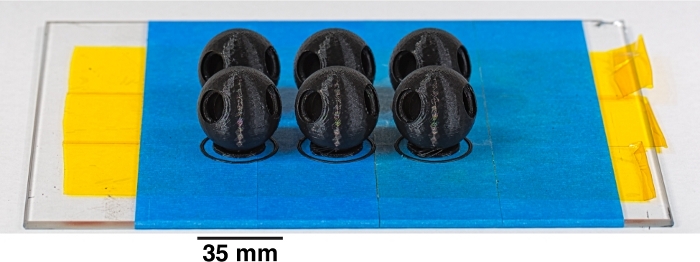
Figure 1: Like-colored atoms or bonds can be printed as arrays. To increase printing efficiency at a slight cost in quality, parts of like color are readily printed in arrays. Here, six PLA carbon atoms are printed together, each positioned on a small raft structure with an outlining brim structure. Please click here to view a larger version of this figure.
- Set the appropriate model processing settings for target prints using Add or Edit Process Settings from the Processes panel of the main window.
NOTE: The software used has selectable default processing settings for PLA, ABS, and other available thermoplastics when adding a new process or editing a process by respectively clicking the Add or the Edit Process Settings from the Processes panel of the main window. Specific adjustments and rationale for the provided molecular model parts follow.- Set the model infill value between 15% and 25%. This will use less filament and result in lighter parts, but the final assembled structures will be strong enough to survive physical manipulation.
- Use 100% infill settings for the connector regions of C-C_bond and H_atom model parts if possible or as needed to increase the durability of connector tabs.
- Choose a print layer thickness of 0.2 mm or smaller to maintain print detail.
- Set the First Layer Speed to a value between 25 and 50% in the Layer tab of the process settings. A slowly printed first layer will improve adhesion to the print bed and will result in more successful overall 3D prints.
- Set the printer extruder and printer bed temperatures to values recommended for the chosen printer filament material. The provided temperatures are starting point recommendations.
- For PLA, set Extruder = 215 °C; Bed = No heating.
- For polyethylene terephthalate glycol-modified (PETG) set Extruder = 235 °C, and Bed = 80 °C.
- For acrylonitrile butadiene styrene (ABS) set Extruder = 245 °C and Bed = 110 °C.
- For C_atom_sp3 model parts, use two Outline/Perimeter Shells with an "Outside-In" Outline Direction to minimize print distortion at the bottom of the sphere. These options are available from the Layer tab of the Process settings window. For all other parts, the "Inside-Out" Outline Direction is recommended for a cleaner surface finish.
- If performing a dual extruder print of the aligned H_atom_dual_bottom and H_atom_dual_top models, optionally turn on an ooze shield option. The slicer will then generate a thin wall geometry around the model that will catch any dripping polymer from the inactive, yet still hot, extruder tip.
- Slice the model into print layers to generate a G-Code toolpath. Click the Prepare to Print! button on the main window, or select the Prepare to Print option under the Edit pulldown menu.
2. Preparation of the printer for printing of parts
- Coat the surface of the printer bed with blue painter's tape for unheated beds. Coat the surface of the printer bed with blue painter's tape and an underlayer of polyimide tape for heated beds.
- Apply a thin layer of glue stick to the blue painter's tape. Glue stick polymer will improve print adhesion to the bed surface.
- Place or close a ventilated enclosure over the printer bed. An enclosure minimizes air currents that can disturb print annealing.
- For PLA, open any/all ventilation ports as rapid cooling is preferred. Turn on a bed fan during printing if possible.
- For PETG, open a limited number of ventilation ports as gradual cooling is preferred. A bed fan is unnecessary during printing.
- For ABS, open a minimum number of ventilation ports as very gradual cooling is preferred. Turn off bed fans during printing.
- Once the printer is prepared, click the "Begin printing over USB" button to send the G-Code to the connected printer and begin the printing process.
3. Finishing and assembly of model structures
- Remove parts from the printer bed. In the case of heated bed prints, remove parts after the bed has cooled to avoid distorting the model during separation.
- Remove raft or brim structures from the base of parts if used. Rub the base of the model part with medium to fine grit sandpaper to remove any remaining attached raft filaments.
- Sand the base of the C_atom_sp3 model parts with medium (120 grit) to very fine (320 grit) sandpaper to remove surface defects. Smooth the surface with the very fine grit sandpaper. Polish the surface to desired finish with a polishing cloth or buffer wheel at low revolution per minute setting.
NOTE: For example, a Dremel tool with a 0.5-inch diameter buffer wheel set to 10,000 rpm can be used for polishing, taking care to not to overly heat the print and cause surface defects.- PLA: Prints typically have a slightly glossy finish following printing as shown in the panels of Figure 2. This finish is marred by coarse sanding, but the glossy finish can be restored with polishing.
- PETG: Prints typically have a slightly glossy finish that can be sanded and restored with polishing as with PLA.
- ABS: Prints typically have a matte or only marginally glossy finish following printing (Figure 3A). A high-gloss finish (Figure 3B) can be achieved by separately dipping the parts in an acetone bath for 1‒2 s and placing them in a ventilated area until the acetone has evaporated and the surface has solidified within typically 12‒24 h.
CAUTION: Acetone is flammable and should be applied sparingly in a fume hood or very well-ventilated area. ABS dissolves in acetone, so parts with layer separation defects due to poor annealing should not be treated with liquid acetone. Acetone will enter models through such defects and dissolve the model infill (Figure 3C). Polishing with acetone vapor is a slower process that will result in a similar effect, though safety precautions should be taken given the flammability of acetone.
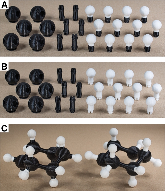
Figure 2: Dual extruder prints can be more visually refined. (A) Dual extruder model hydrogen atom prints are visually more cohesive than (B) all white model hydrogen atom prints. (C) When connected together to form complete cyclohexane rings, the assembled PLA models are functionally identical. Please click here to view a larger version of this figure.
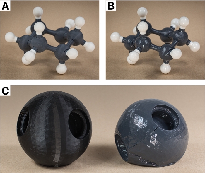
Figure 3: ABS models can be chemically processed for a glossy finish. (A) ABS model prints tend to have a more diffuse or matte appearance, but (B) after chemically treating the parts with a brief dip in acetone they gain a high gloss finish. (C) If acetone enters the interior of the print through layer separation defects, the acetone will dissolve the model from the inside out, causing it to collapse. Please click here to view a larger version of this figure.
- Insert connector ends of C-C_bond and H_atom model parts into sockets on C_atom_sp3 model parts according to desired bonding topology. Squeeze model parts together until an audible click is heard. Once connected, the single bond should freely rotate about this connection without falling apart.
NOTE: The connection fit is tight, so this may require significant force for models with scaling greater than 100%. The provided parts are not intended to be separated after connecting them together, but they can be separated with a very significant applied force. Rotation about a connected bond is a desired feature for the provided parts and models. Locking rotation requires an atom model (an sp2 hybridized carbon, for example) with a fixed structure in the connection socket that inserts between the spacings of the tabs on the end of the bond model. - Assemble all printed parts according to the desired molecular structure. Saturate all C_atom_sp3 model parts by filling any open socket with an H_atom model part. For a ring like cyclohexane, close the ring with a C-C_bond model part between C_atom_sp3 model parts.
Results
The protocol provided covers a variety of potential options for interactive molecular model construction. As a basic and unifying example for a molecular assembly using these model parts, we have chosen to assemble interactive cyclohexane structures at a variety of scales. Figure 2 shows the parts necessary for this structure: six C atoms, six C-C bonds, and twelve H atoms. These specific prints were crafted using both printers listed in the Table of Materials. The more costly dual extruder printer enables the production of dual color components; here the two-colored hydrogen atom structures with the color change at the midpoint of the bond (Figure 2A). The mono-colored hydrogens in Figure 2B print in about 50‒60% less time due to the lack of an ooze shield structure and lack of polymer retractions in switching between active extruders. The assembled cyclohexane structures (Figure 2C) are functionally equivalent, though the dual extruder prints tend to look moderately more refined.
The PLA models in Figure 2 have reasonably nice finish that is more refined than ABS models straight off the printer (Figure 3A). Chemical treatment of ABS models with acetone gives a smooth and high gloss finish that almost gives the surface a wet look (Figure 3B). Such finishing can be troublesome, particularly if ABS models are not annealed well. Large models printed with ABS are prone to layer separation defects. Layer separation defects happen when the previous layer cools before the extruder can traverse over to lay down the next layer. It is critically important for large ABS prints that the environment around the heating bed of the printer remain at an even and warm temperature to slow down the cooling rate. If a print with a layer defect is submerged in acetone, the acetone will enter the model and dissolve the interior support structure. This will collapse the model from the inside as shown in Figure 3C.
A visually distinct appearance is secondary to functionality of the model structures. The connectors were designed to enable free rotation about single bonds. To test their utility in different systems, four different sets of part sizes were printed, with the carbon atom diameter running from 17.5 mm, 35 mm, 70 mm, and 112 mm. The assembled cyclohexane structures (Figure 4) were all able to flex, distort, and adopt relevant conformers in the same manner. The smallest of these models was the most prone to print flaws, making this size potentially too small and not recommended without tweaking the relative size of the parts. One of the primary benefits to the smaller prints is the speed of printing. An array of six of the smallest carbon atoms printed in around 2 h, as compared to the 10 h required for a single carbon atom of the largest size. While slow to print, large models are potentially more effective for communication in lecture settings where it would be difficult to see the motion of a small structure from a distance.
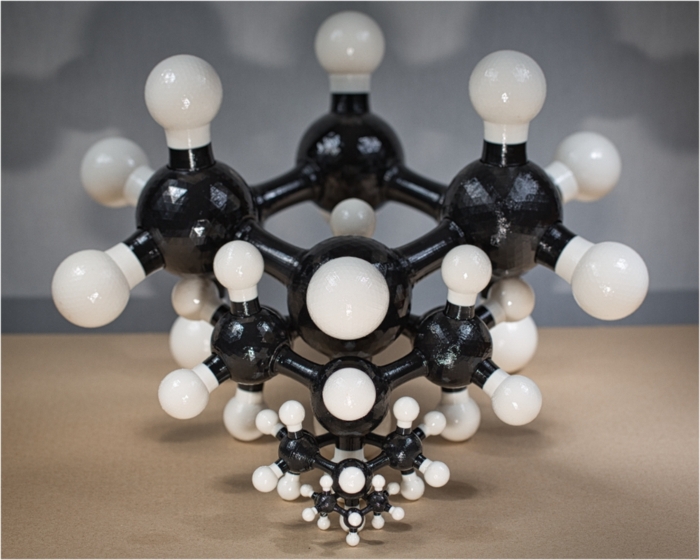
Figure 4: Models are functional at a variety of scales. To illustrate how the models can be printed for different purposes, cyclohexane models were assembled at four different scales and all retain the same functionality. The carbon atoms of the largest are larger than a softball (112 mm diameter) while the assembled cyclohexane of the smallest could fit within a softball. Please click here to view a larger version of this figure.
The dynamic aspect is one of the key attributes that separate these structures from other printable molecular models. Since the atoms can readily rotate relative to one another, the structures can be distorted to snap into the different representative conformers of cyclohexane. Figure 5 shows the chair, boat, and the transition state structure for interconversion between their respective configuration spaces. This transition state point has four labeled carbon atoms in a nearly planar geometry24,28, the same transition state structure that one achieves doing B3LYP/6-311+G(2d,p) calculations29. Following the same transition state imaginary frequency motion, slightly twisting 2 up and 3 down will snap the model into the boat conformer landscape, while slightly twisting 2 down and 3 up will return the structure to the chair conformer.
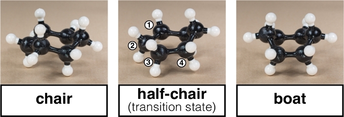
Figure 5: Conformers of cyclohexane are fully accessible. As the atoms can rotate about their bonds, the models can adopt the sterically locked chair and more conformationally free boat forms. The transition state between these forms involves four nearly coplanar carbon atoms in the ring. Lightly twisting 2 up with 3 down will slip the model to the boat conformer, while twisting 2 down with 3 up will return the model to the chair conformer. Please click here to view a larger version of this figure.
The state point free energy estimates (Supplementary Table S1) from B3LYP/6-311+G(2d,p) calculations of optimized state points (Supplementary Files S6‒S9) give a gap between the twist-boat and boat conformers of 0.8 kcal/mol, which is very close to thermal energy at 298.15 K. This suggests that conversion between these should sample nearly freely. The gap between the chair conformer and interconversion transition state is more than ten times this value, indicating that the chair should be conformationally locked in comparison. This is illustrated in Figure 6, which shows estimated average conformer energy when each carbon atom location relative the ring plane is latitudinally projected onto a sphere over the course of a gas phase molecular dynamics calculation30,31. In the chair conformer on the left, the energy is low when the carbon atoms are displaced above or below the ring plane, but it ramps up dramatically if they displace to align with the ring plane. In the boat conformer, the conformer energy is relatively low when carbons are in the ring plane (twist-boat state), and the more highly displaced boat conformer is not at a drastically higher energy. These configuration landscapes can be explored with the 3D printed cyclohexane models, with the chair conformer only being able to locally vibrate while the boat conformer can smoothly undulate from one pair of opposite carbon atoms to the next.
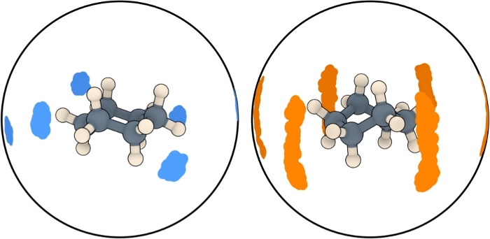
Figure 6: Model behavior matches calculations. In the chair and boat conformer states, the latitudinal displacement of carbon atoms about the ring plane over the course of a Molecular Dynamics calculation can be projected onto the surface of an enclosing sphere. While the chair form is most energetically stable, it is locked and can only interconvert to the inverted form by passing through a high energy transition state. Both calculations and printed model flexibility indicate that the boat and twist-boat conformers are separated by close to 1 kBT at 298.15 K, allowing nearly free latitudinal displacement of carbon atoms in this form. Please click here to view a larger version of this figure.
Supplementary Table S1: State point free energy estimates. Please click here to download this table.
Supplementary File 1. Please click here to download this file.
Supplementary File 2. Please click here to download this file.
Supplementary File 3. Please click here to download this file.
Supplementary File 4. Please click here to download this file.
Supplementary File 5. Please click here to download this file.
Supplementary File 6. Please click here to download this file.
Supplementary File 7. Please click here to download this file.
Supplementary File 8. Please click here to download this file.
Supplementary File 9. Please click here to download this file.
Discussion
The primary aim of this study is to report a protocol for the crafting of dynamic molecular models with commodity 3D printers. These printers are increasingly accessible, often even free to use in libraries, schools, and other venues. Getting started involves making choices about both the models to print and the materials to use and deciding from these options may require some inspiration regarding what creative additive manufacturing can do for research and instruction. To address these issues, we provide some practical material recommendations, suggested model parts, a 3D printing protocol, and an example application, each of which warrant further discussion.
There are many choices of thermoplastic for use in 3D printing. We highlight three in the presented protocol as these three materials are currently the most widely available for do-it-yourself 3D printing. The choice may depend on what material is supported by an available 3D printer, for example many open access facilities will only print with PLA because of environmental constraints. PLA is a biodegradable and compostable material that has a printing protocol with mild temperature settings. Both ABS and PETG are less environmentally friendly and not generally recyclable, though PETG is based on highly recyclable polyethylene terephthalate (PET) and may eventually see wider spread reprocessing like PET. Sustainable printing practices would involve printing few parts at a time to ensure both print quality and print success, this while using as little discarded material (support structures, rafts, ooze shields, etc.) as possible. PLA can be brittle, so if available, ABS and PETG thermoplastics can result in prints that are more mechanically resilient and have improved layer adhesion, respectively. These properties could be desirable for an interactive molecular model that will see regular manipulation in a laboratory or classroom setting.
The models presented here take these considerations into account, though they are firstly engineered to work together to enable dynamic molecular model construction. At the default scale, they will assemble successfully into interactive molecular structures. They can readily be scaled up to large models, though assembly will require more force as the connection prongs are less easy to distort at larger size. In shrinking the components, a 50% reduction in size will still work with minor modifications, such as shrinking the carbon atom model to 48‒49% while keeping the bond and hydrogen atom at 50% to enable tighter connections between parts in PLA prints. Models this small are more delicate and often require raft structures to successfully print, but they are still functional as dynamic molecular models.
The thermoplastic material and chosen models to print are the two most critical aspects of a 3D printing protocol. The chosen thermoplastic will dictate the temperature, adhesion, annealing, and finishing considerations and options. If the available 3D printer does not have a heated bed, PLA is the only one of the presented thermoplastic choices that will print parts reproducibly. While the provided parts are designed to reproducibly print with different thermoplastics and hold up to dynamic manipulation, prints will degrade with use and crack, often between print layers, when placed under increasing stress. In such situations, it is easy and relatively cost effective to print a replacement part.
The dynamic functionality of molecular assemblies printed from the provided models differentiates this work from other available and 3D printable models that primarily highlight connectivity and bonding types. The dynamical aspects are presented in small part with the example cyclohexane structure. The configuration landscape of cyclohexane is directly accessible by hand using these models, and the topologies of these landscapes are in general agreement with computational investigations. Much of this comes from a respect for the specifics of molecular geometry and degrees of freedom in these physical modeling components. In Linus Pauling's commentary on their success in discovering the structure of the α-helix1, they claimed that their contemporaries faced difficulties coming from idealistic integral assumptions and adopting "...only a rough approximation to the requirements about interatomic distances, bond angles, and planarity of the conjugated amide group, as given by our investigations of simpler substances." More quantitative insight along these lines requires more specific detail than the considerations taken in building these model parts, but these models and recommendations provide a foundation for general interactive physical investigation of molecular systems. These models are an extension of 3D printable model kits we have been producing for research and outreach activities for several years prior to this report, and additional component parts that are compatible with both these models and the described protocol are available from the authors to enable more diverse bonding arrangements and dynamical action.
Disclosures
The authors have nothing to disclose.
Acknowledgements
This work was supported by the National Science Foundation (NSF) under Grant No. CHE-1847583.
Materials
| Name | Company | Catalog Number | Comments |
| ABS: Black 1.75 mm filament spool, 1 kg | MakerBot | MP01969 | Obtained from reseller (B&H and/or Amazon). |
| ABS: Dark Gray 1.75 mm filament spool, 1 kg | Amazon | B07T6W8TRF | Obtained from reseller (B&H and/or Amazon). |
| ABS: White 1.75 mm filament spool, 1 kg | Hatchbox | B00J0H6NNM | Obtained from reseller (B&H and/or Amazon). |
| Crown Acetone, 1 Gallon | Crown | 206539 | Obtained from a hardwares store (Lowes). |
| MakerGear M2 | MakerGear | This printer is more costly than inexpensive FDM printers obtainable on Amazon or other sites, but it is engineered for more consistent performance. | |
| MakerGear M2 Dual | MakerGear | This model printer is no longer available for purchase. It has been replaced with a new model that has independent dual extruders. | |
| Multi-Surface 1.88-in Painters Tape | 3M | 116480 | Obtained from a hardwares store (Lowes). |
| PETG: Pink 1.75 mm filament spool, 1 kg | Amazon | Obtained from reseller (B&H and/or Amazon). No longer available from this company. | |
| PETG: White 1.75 mm filament spool, 1 kg | Amazon | Obtained from reseller (B&H and/or Amazon). No longer available from this company. | |
| PLA: Black 1.75 mm filament spool, 2 lb | MakerBot | MP05775 | Obtained from reseller (B&H and/or Amazon). |
| PLA: Cool Gray 1.75 mm filament spool, 2 lb | MakerBot | MP05784 | Obtained from reseller (B&H and/or Amazon). |
| PLA: White 1.75 mm filament spool, 2 lb | MakerBot | MP05780 | Obtained from reseller (B&H and/or Amazon). |
| POLYIMIDE TAPE (2" ROLL) | MakerGear | Provided with the printer from MakerGear, though obtainable from a variety of sources. | |
| Simplify3D | Simplify3D | Slicer softward used in prints. This software can be purchased from the company, or it can be purchased from MakerGear and other 3D printer makers. |
References
- Pauling, L., Corey, R. B., Branson, H. R. The structure of proteins: Two hydrogen-bonded helical configurations of the polypeptide chain. Proceedings of the National Academy of Sciences. 37 (4), 205-211 (1951).
- Claussen, W. F. Suggested Structures of Water in Inert Gas Hydrates. The Journal of Chemical Physics. 19 (2), 259-260 (1951).
- Claussen, W. F. A Second Water Structure for Inert Gas Hydrates. The Journal of Chemical Physics. 19 (11), 1425-1426 (1951).
- Watson, J. D., Crick, F. H. C. Molecular Structure of Nucleic Acids: A Structure for Deoxyribose Nucleic Acid. Nature. 171 (4356), 737-738 (1953).
- Watson, J. D. . The double helix: a personal account of the discovery of the structure of DNA. , (1981).
- Cademartiri, R., et al. A simple two-dimensional model system to study electrostatic-self-assembly. Soft Matter. 8 (38), 9771-9791 (2012).
- Reches, M., Snyder, P. W., Whitesides, G. M. Folding of electrostatically charged beads-on-a-string as an experimental realization of a theoretical model in polymer science. Proceedings of the National Academy of Sciences. 106 (42), 17644-17649 (2009).
- Tricard, S., et al. Analog modeling of Worm-Like Chain molecules using macroscopic beads-on-a-string. Physical Chemistry Chemical Physics. 14 (25), 9041-9046 (2012).
- Tricard, S., Stan, C. A., Shakhnovich, E. I., Whitesides, G. M. A macroscopic device described by a Boltzmann-like distribution. Soft Matter. 9 (17), 4480-4488 (2013).
- Capel, A. J., Rimington, R. P., Lewis, M. P., Christie, S. D. R. 3D printing for chemical, pharmaceutical and biological applications. Nature Reviews Chemistry. 2 (12), 422-436 (2018).
- Jones, O. A. H., Spencer, M. J. S. A Simplified Method for the 3D Printing of Molecular Models for Chemical Education. Journal of Chemical Education. 95 (1), 88-96 (2018).
- Paukstelis, P. J. MolPrint3D: Enhanced 3D Printing of Ball-and-Stick Molecular Models. Journal of Chemical Education. 95 (1), 169-172 (2018).
- Pinger, C. W., Geiger, M. K., Spence, D. M. Applications of 3D-Printing for Improving Chemistry Education. Journal of Chemical Education. 97 (1), 112-117 (2020).
- Robertson, M. J., Jorgensen, W. L. Illustrating Concepts in Physical Organic Chemistry with 3D Printed Orbitals. Journal of Chemical Education. 92 (12), 2113-2116 (2015).
- Au - Da Veiga Beltrame, E., et al. 3D Printing of Biomolecular Models for Research and Pedagogy. JoVE. (121), e55427 (2017).
- Fourches, D., Feducia, J. Student-Guided Three-Dimensional Printing Activity in Large Lecture Courses: A Practical Guideline. Journal of Chemical Education. 96 (2), 291-295 (2019).
- Rossi, S., Benaglia, M., Brenna, D., Porta, R., Orlandi, M. Three Dimensional (3D) Printing: A Straightforward, User-Friendly Protocol To Convert Virtual Chemical Models to Real-Life Objects. Journal of Chemical Education. 92 (8), 1398-1401 (2015).
- Griffith, K. M., Cataldo, R. d., Fogarty, K. H. Do-It-Yourself: 3D Models of Hydrogenic Orbitals through 3D Printing. Journal of Chemical Education. 93 (9), 1586-1590 (2016).
- Carroll, F. A., Blauch, D. N. 3D Printing of Molecular Models with Calculated Geometries and p Orbital Isosurfaces. Journal of Chemical Education. 94 (7), 886-891 (2017).
- Van Wieren, K., Tailor, H. N., Scalfani, V. F., Merbouh, N. Rapid Access to Multicolor Three-Dimensional Printed Chemistry and Biochemistry Models Using Visualization and Three-Dimensional Printing Software Programs. Journal of Chemical Education. 94 (7), 964-969 (2017).
- Carroll, F. A., Blauch, D. N. Using the Force: Three-Dimensional Printing a π-Bonding Model with Embedded Magnets. Journal of Chemical Education. 95 (9), 1607-1611 (2018).
- The NIH 3D Print Exchange. The NIH 3D Print Exchange: A Public Resource for Bioscientific and Biomedical 3D Prints. 3D Printing and Additive Manufacturing. 1 (3), 137-140 (2014).
- Penny, M. R., et al. Three-Dimensional Printing of a Scalable Molecular Model and Orbital Kit for Organic Chemistry Teaching and Learning. Journal of Chemical Education. 94 (9), 1265-1271 (2017).
- Nelson, D. J., Brammer, C. N. Toward Consistent Terminology for Cyclohexane Conformers in Introductory Organic Chemistry. Journal of Chemical Education. 88 (3), 292-294 (2011).
- Anet, F. A. L., Bourn, A. J. R. Nuclear Magnetic Resonance Line-Shape and Double-Resonance Studies of Ring Inversion in Cyclohexane-d11. Journal of the American Chemical Society. 89 (4), 760-768 (1967).
- Mayes, H. B., Broadbelt, L. J., Beckham, G. T. How Sugars Pucker: Electronic Structure Calculations Map the Kinetic Landscape of Five Biologically Paramount Monosaccharides and Their Implications for Enzymatic Catalysis. Journal of the American Chemical Society. 136 (3), 1008-1022 (2014).
- Satoh, H., Manabe, S. Design of chemical glycosyl donors: does changing ring conformation influence selectivity/reactivity. Chemical Society Reviews. 42 (10), 4297-4309 (2013).
- Allinger, N. L. Conformational analysis. 130. MM2. A hydrocarbon force field utilizing V1 and V2 torsional terms. Journal of the American Chemical Society. 99 (25), 8127-8134 (1977).
- . . Gaussian 09 v.Revision C.01. , (2010).
- Abraham, M. J., et al. GROMACS: High performance molecular simulations through multi-level parallelism from laptops to supercomputers. SoftwareX. 1-2, 19-25 (2015).
- Wang, J., Wolf, R. M., Caldwell, J. W., Kollman, P. A., Case, D. A. Development and testing of a general amber force field. Journal of Computational Chemistry. 25 (9), 1157-1174 (2004).
Reprints and Permissions
Request permission to reuse the text or figures of this JoVE article
Request PermissionThis article has been published
Video Coming Soon
Copyright © 2025 MyJoVE Corporation. All rights reserved