Capacitance
Source: Yong P. Chen, PhD, Department of Physics & Astronomy, College of Science, Purdue University, West Lafayette, IN
This experiment will use commercial capacitors and a parallel plate capacitor to demonstrate the concept of capacitance. A capacitor stores opposite charges on two conductors, for example two opposite metal plates, leading to a potential difference (voltage drop) between the two conductors. The amount of charge on each conductor is proportional to this voltage drop, with the capacitance as the proportionality factor. If the voltage is changing with time, the current flowing into the capacitor will be proportional to the rate of that change, and again the capacitance is the proportionality factor.
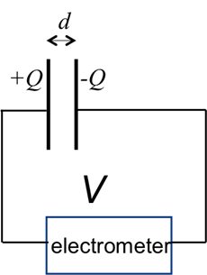
The capacitance of the parallel plate capacitor is the product of the dielectric constant with the distance between the plates divided by the area of the plate. This experiment will demonstrate the proportionality with distance by first depositing some charge onto the capacitor and then using a high-impedance voltmeter (electrometer) to monitor the voltage between the plates as the distance is increased. The voltage change will also be monitored with a dielectric material, such as a plastic plate inserted into the space between the metal plates.
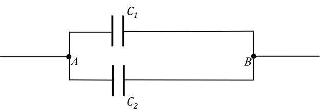
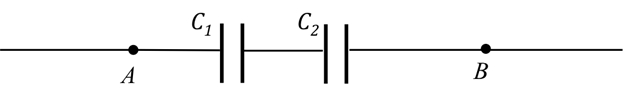
A capacitance meter will be used to directly measure the capacitance, as well as to measure parallel and series connections of commercially-available capacitors and to study how the total capacitance is related to individual capacitances.
1. Charging a Capacitor
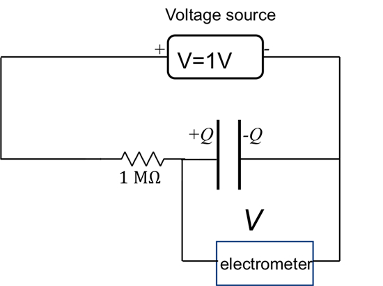
- Obtain a commercial capacitor with capacitance C = 470 µF (or some similar value), a programmable voltage source, and an amp-meter (or multi-meter that can measure current).
- With the voltage source set to 0 V, connect the "+" terminal of the voltage source to one terminal of the capacitor, with the amp-meter in between, and connect the "−" terminal of the voltage source to the other terminal, as in Figure 1. The connect
For a capacitor, a plot of current I versus ramp rate ΔV/Δt is linear, as shown in Figure 7. Since the current is the rate of the change in the charge Q on one conductor terminal, this also reflects the linear relationship between charge Q and voltage V for a capacitor (Equation 1). The slope of the line is equal to the capacitance of the capacitor (Equation 2).
In this experiment, the charging of a capacitor was demonstrated, where the current is the product of the capacitance and the rate of change of voltage. By observing how the voltage varies given a fixed charge, we have demonstrated how the capacitance of a parallel plate capacitor varies with the separation and with the medium between the plates.
The capacitance meter can also be used to directly measure the capacitance, and determine the total capacitance for capacitors connected in parallel
Skip to...
Videos from this collection:

Now Playing
Capacitance
Physics II
43.7K Views

Electric Fields
Physics II
77.4K Views

Electric Potential
Physics II
104.4K Views

Magnetic Fields
Physics II
33.4K Views

Electric Charge in a Magnetic Field
Physics II
33.7K Views

Investigation Ohm's Law for Ohmic and Nonohmic Conductors
Physics II
26.2K Views

Series and Parallel Resistors
Physics II
33.1K Views

Inductance
Physics II
21.5K Views

RC/RL/LC Circuits
Physics II
142.7K Views

Semiconductors
Physics II
29.6K Views

Photoelectric Effect
Physics II
32.6K Views

Reflection and Refraction
Physics II
35.8K Views

Interference and Diffraction
Physics II
90.9K Views

Standing Waves
Physics II
49.7K Views

Sound Waves and Doppler Shift
Physics II
23.4K Views
Copyright © 2025 MyJoVE Corporation. All rights reserved